Safety has become an important factor in the power industry due to the risks linked to catastrophic failures of electrical equipment. An internal fault, for example, followed by high fault-current and high temperature arcing can result in explosion and fire that spreads to surrounding equipment. Such risk should therefore be a concern across the power sector, especially to utilities that must bear the costs and consequences of failures.
With linear installation in vertical and horizontal layouts, underground cables are exposed to greater threat from fire. Moreover, the impact can often be catastrophic due to relative ease of flame spread and propagation. There are also added risks of environmental problems in cases where significant amounts of fire effluents are dispersed.
This edited past contribution to INMR by experts at the Testing & Certification Division of KEMA Labs in Italy highlighted situations of highest potential danger. It also discussed testing both in the field and in the laboratory to assess solutions that can increase safety and mitigate the impact of cable and accessory failures.

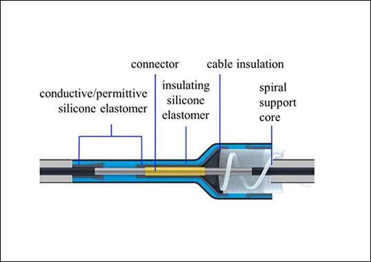
Cables and accessories form an integral part of power networks. For example, whenever there is a transition to them from overhead lines or busbars, cable ends are sealed using terminations of different construction, depending on whether the application is medium or high voltage. In both cases, however, special care must be taken in regard to pollution withstand since terminations are an interface with the service environment. Indeed, cable accessories such as joints and terminations have been shown to often be the ‘weakest link’ in the system. Accessories have to handle the high electrical stresses in the cable insulation and also to cope with the thermo-mechanical forces exerted by cables. Such interaction with the cable significantly influences the performance demanded of them.
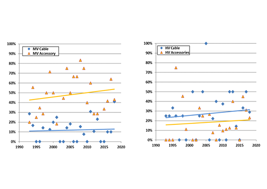
In recent years, growing numbers of XLPE cable systems has been introduced into HV networks and more are planned. Therefore, the number of relevant cable accessories is also increasing. In this highly competitive cable and accessory marketplace, manufacturers have devoted great effort to realize leaner designs while also ensuring enhanced performance. Yet despite ongoing improvements in both materials and production methods, failure rates are not decreasing. Instead, surveys show that from 20 to 50% of all type tests on cable accessories result in failure. Given this, one suggestion is that only components tested and certified at independent laboratories should be selected to provide reassurance for specific quality level. Moreover, safety becomes even more important when talking about HV and UHV facilities and related components due to unique connections. In this regard, special tests have been introduced by utilities to verify their safe performance even under extreme conditions.
Proper selection of the ratings and characteristics of medium and high voltage components, together with high quality level, are important in reducing risk of failures. Nonetheless, the possibility of such events can never be fully disregarded. Therefore, laboratory testing to simulate internal fault is a useful tool to ensure that selected components have safe performance in case of failure and reduced risk of violent explosion or fire ignition.

MV Network Testing Experience
In Italy, ENEL’s MV network has a length of about 300,000 km, about 35% of which is formed by underground cables. These are mostly XLPE but EPR and impregnated lead sheath paper cables of 15 to 20 kV are also present. Different kinds of joints are used, including transition joints. In most cases, such cable networks are buried and protected against damage using bent cement tiles or recycled PVC plates. However cables can also be laid, especially in large towns, tunnels and underground passages. In such environments, breakout of fire and its propagation is a risk given that air is allowed to circulate. Tests have therefore been performed in the past on 12/20 kV 240 mm2 cable systems to gain experience with different protection solutions as well as to highlight the effects of internal arcing and evolution of phenomena such as explosion and fire.
HV Network Testing Experience
For years now the Italian Transmission System Operator has been interested in assessing behavior of HV cable system in underground installations. The main goal has been to verify the potential for damage to adjacent cables, fire development and gas emissions. For example, tests have been performed on full-scale 400 kV 1600 mm2 cables laid in a tunnel mock-up where breakdown was induced by drilling a hole through the insulation and inserting a metallic wire to connect internal conductor to metallic sheath. The short circuit current subsequent to the artificial breakdown caused vaporization of the connection wire and the resulting plasma was sufficient to maintain the electrical arc for the duration of the short circuit. One key test outcome was that, given a short circuit current of 63 kA, a safety distance of 350 mm is necessary to ensure that fire does not propagate to nearby cables. With a short circuit current of 40 kA, this safe distance is reduced to 300 mm. Moreover, for cables buried in a suitable sand backfill to a depth of 1.65 m and protected by a concrete slab, a 63 kA short circuit current showed no significant mechanical effects on the surface. In other words, the sand bed had a consistent capability to absorb all related mechanical impact.
Industry Developments
These days, more and more TSOs are searching for innovative solutions to develop their grids and this has not only boosted demand for new components and equipment but also the need to ensure these deliver the highest quality. Impartial test-based certification by third party test laboratories utilizing relevant standards is the best way for manufacturers to offer customers such reassurance. Moreover, some clients are now asking for specific components to undergo more stringent versions of the test standard or pass specialized tests beyond those normally required for certification.
Based on laboratory tests performed according to European technical specifications and standards, experience has recently been gained on internal arc tests of HV cable terminations and bushings. The following sections deal with laboratory simulation of layouts intended to deal with concern among utilities in the possible consequences of explosion and fire propagation in urban tunnels.
Test Methods for Power Arc Events
An unexpected power arc fault event in a transmission system can lead to serious damage to installed equipment as well as to the environment and in certain circumstances result in severe injuries. In metropolitan areas with underground transmission or distribution systems, such undesirable events could involve experienced workers operating on the system or members of the public who happen to be passing near the damaged power source, located few meters below ground. Use of high performance materials, smart equipment, correct design criteria and proper installation are not sufficient to nullify risk of fault due to unpredictable events. Hence, this emerging scenario needs to be explored and evaluated to verify reliability of such T&D methods, especially for underground tunnels where public services are typically located side-by-side.
Testing performed on specific layouts and assemblies has therefore taken on increased relevance to better understand all phenomena and consequences related to faults. Moreover, this approach is the only practical method to assess and demonstrate whether or not a designated solution can properly withstand critical events. At the same time, recent market requirements are creating technical challenges both for the testing service provider and the manufacturer, for example:
1. An applicable international Standard or Regulation (e.g. Technical Brochure) is still needed for these specific layouts. Lack of generalized test methods has therefore required TSOs and utilities to create customized procedures based on their own knowledge and definition of requirements to be fulfilled by manufacturers;
2. Based on Point 1, accomplishment of any final test outcome, as quoted into the ad-hoc technical specification, is a challenge for the manufacturer, who bears final responsibility to achieve positive results. An international standard would regulate performance required of the manufacturer while also guaranteeing sufficient quality and reliability to the end user. At the same time, it would help balance results achievable with actual capabilities among third party test laboratories, thereby avoiding unnecessarily complex testing requirements;
3. Manufacturers and laboratories are involved in a demanding and time-consuming process that requires resources to prepare and plan all details of testing, e.g.:
• Third party laboratories have to evaluate, on a case-by-case basis, all requests and typically adopt custom solutions to cover client needs: e.g. specific layout to be realized, measuring systems to be developed, including potential of cost savings as well as the ability to fulfill last minute deviations due to unexpected occurrences during the test;
• Several high speed cameras (HSC) are required to have more views and record the event from different directions, also considering presence of the tunnel and development of fire and smoke. An HSC recording is always recommended to permit review in slow motion and to have greater clarification of the event being recorded, e.g. to identify behavior of metal parts, arcing, blast and to have a better understanding of relevant phenomena.
• Proper coordination between laboratory and customer and fine-tuning of the program are also necessary. Coordination is key to reducing numbers of samples that need to be tested and enhancing the outcome of the test procedures.
Below is a case history illustrating how the abive market factors have impacted specific testing of a HV cable system operating in an urban setting:

Case History Test Layout & Assembly
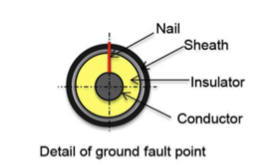
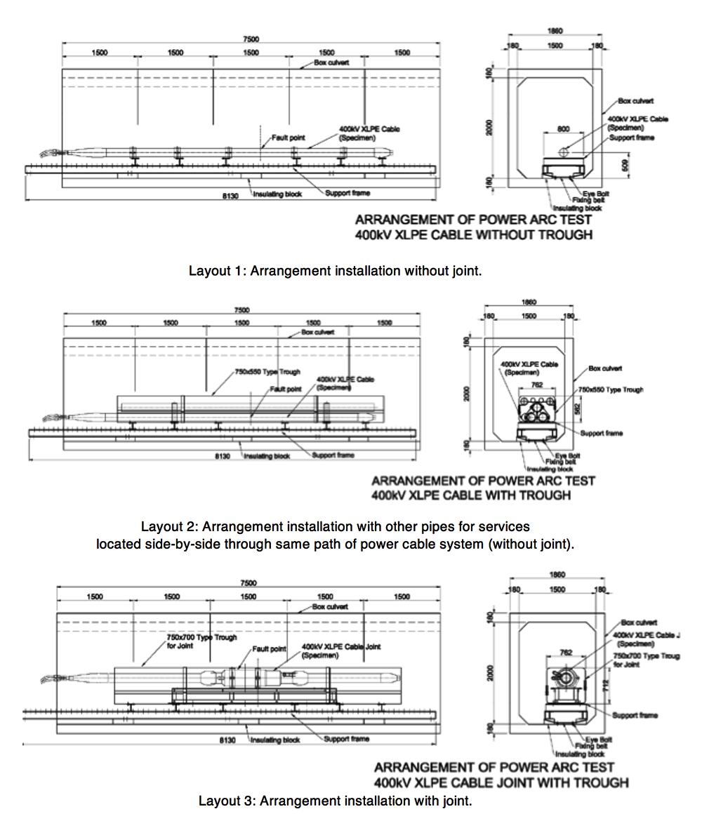
The aim of these tests was to evaluate effects from the energy produced by an arc in several installation arrangements representative of a 400 kV XLPE (single phase) cable system located in an urban tunnel. The cable joint, being part of the system, was included but in only some of the realized configurations. Arc initiation was accomplished by placing a fuse nail pre-installed on the specimens under evaluation (see Fig. 1). In accordance with presumed service conditions, the whole specimen was wired with aramid band having different thicknesses and application methods on samples.
According to client request, the entire assembly to be tested was located in a representative tunnel section of 8 m length and having a breach of 4 m2 (see Fig. 2). Different layouts were simulated (see Fig. 3). For example, in one case the full assembly was placed inside a flame retardant fiber reinforced plastic (FRP) cable trough. The main differences among the six layouts were: presence of a joint, fire prevention countermeasures and their method of application around the sample. This way, based on test results, comparisons and evaluations could be made between different adopted solutions. Both sides of the tunnel were left open to allow recording with high-speed cameras as well as for extinguishing the fire at conclusion of the test.

Evaluation of Arc Energy Effect in Different Cable System Configurations
Power arc tests were performed on several cable system configurations and arrangements. The goal was to verify the effect of the arc energy released in 1 second by a flowing current of 63 kArms through the selected arrangement and to compare this to expected design performance. Each test configuration had to be properly realized in advance. For example, steps included application of a fuse nail between conductor and metal screen for the faulty section, realization of the set-up, application of an FRP fire resistant cable trough as well as the aramid/blast wrapped around the specimen. The arrangement was completed by positioning mock-up pipelines representative of services located together with the cable so as to simulate a real service application under fault.
Finally, to conclude the pre-testing phase, sensors were placed inside the tunnel to monitor the effects of the energy released from the arc. It was important to maintain the same position for these sensors during the different tests to allow proper comparison among the configurations and methods adopted to suppress damage. In addition, to avoid premature current interruption (i.e. a current peak of 2.5 p.u. was achieved in some test sessions and 2.8 p.u. in other cases) properly dimensioned, reinforced outgoing connections to the power supply were needed. Withstanding the electrodynamics forces developed during current circulation had to be assured to avoid unwanted test repetition and the need to prepare additional samples.
Several physical parameters were recorded during test sessions using dedicated instruments and sensors. The main measurements of current intensity and arc energy released were integrated together with monitoring pressure rise and temperature increase due to arc ignition and fire propagation along the tunnel. Tables 1 and 2 list the physical parameters typically measured during each test session.
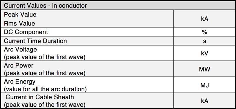
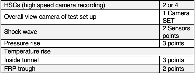
In the case of temperature measurement, separate sampling time was requested. This allowed greater detail not only during the first second of permanence of the arc but also during the following minutes of fire development. Such an approach was regarded as important not only to monitor temperatures reached inside the tunnel but also their distribution around the fault point. Moreover, a shock wave sensor was also utilized during testing.

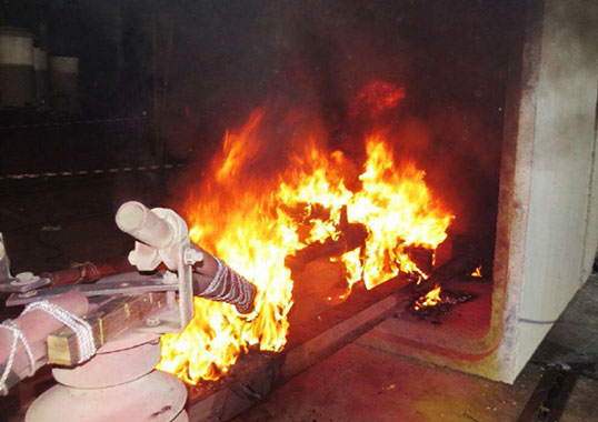
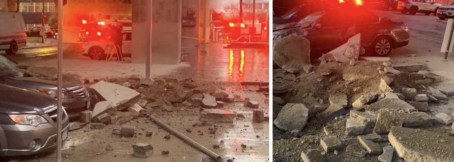
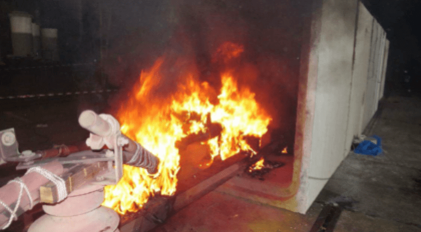
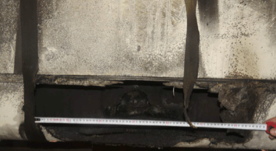
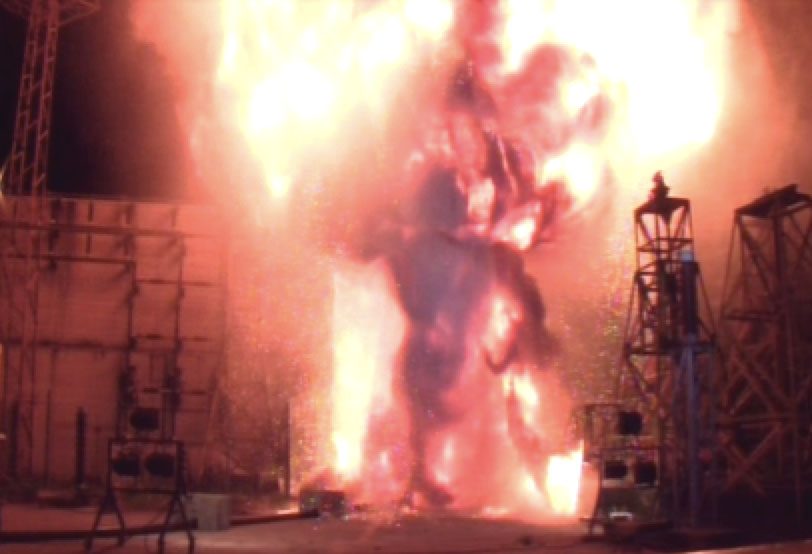
During the first second of arc permanence, temperature and pressure increase quickly and reach such values that they must be seriously taken into account. It is noteworthy that temperature values, measured in the same sensor positions along the tunnel, can be different and depend on the damage suppression being realized in each specific configuration being tested. For example, when no fire prevention solution is adopted and in the case of the layout configuration without installed joint, temperature in the tunnel increases rapidly above 650°C. The arc in this case results in an energy release of about 90 MJ together with presence of fire after the arc is extinguished. This is sufficient to cause serious further damage to the system and propagate flames to other piping installations, thereby worsening an already critical situation. Moreover, an elevated pressure wave developed in the tunnel due to the blast and values exceeding 10 bar were recorded. Together, the combined visual and acoustic effects of the explosion confirm how important such testing is in order for a TSO/utility to realize the dramatic potential consequences and impact on the cable of any internal fault situation (see Figs. 4 and 5).
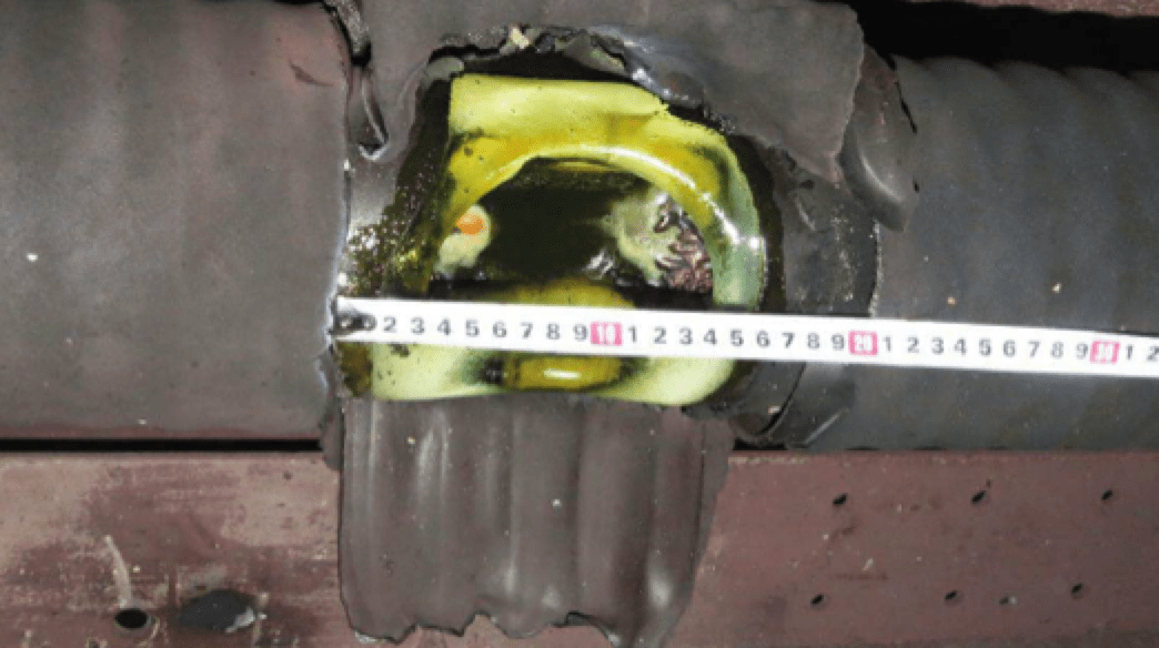
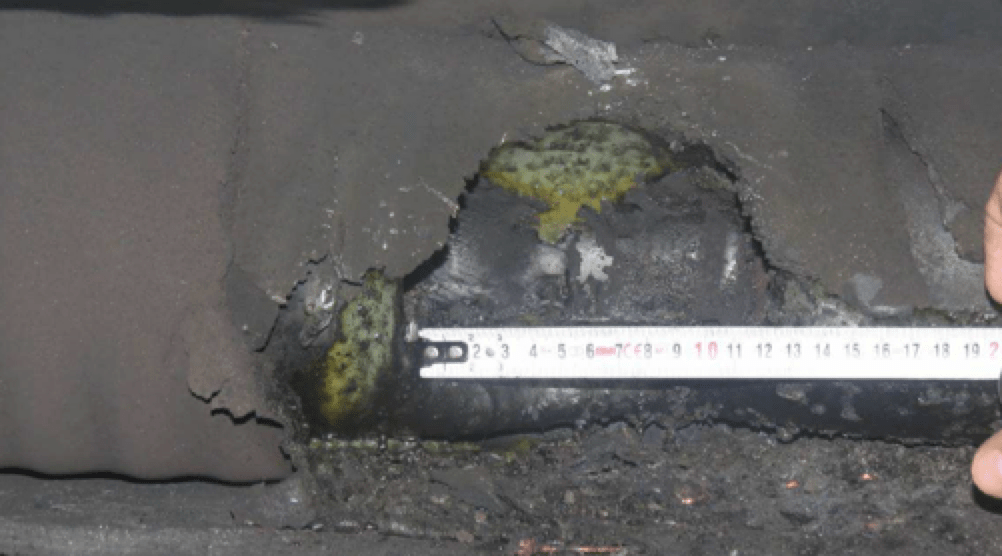
Another cable system configuration, also without installed joint, was also tested but this time equipped with a fire prevention countermeasure in place. This consisted of application of aramid band around the cable and distributed through the cable trough. This solution showed major reduction in temperature values measured along the tunnel to values around 380°C even though pressure was of the same order of magnitude as in the previous test configuration. A further test having the same layout and arrangement but where application interval of the aramid band was reduced showed further reduction in temperature inside the tunnel to less than 300°C but the cable trough was damaged near the fault point (see Figs. 6 and 7).
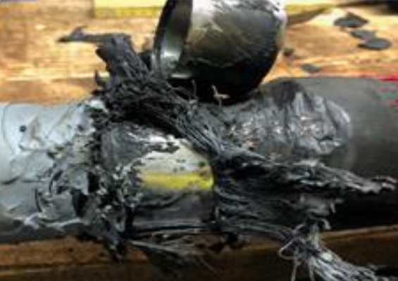
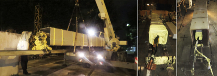
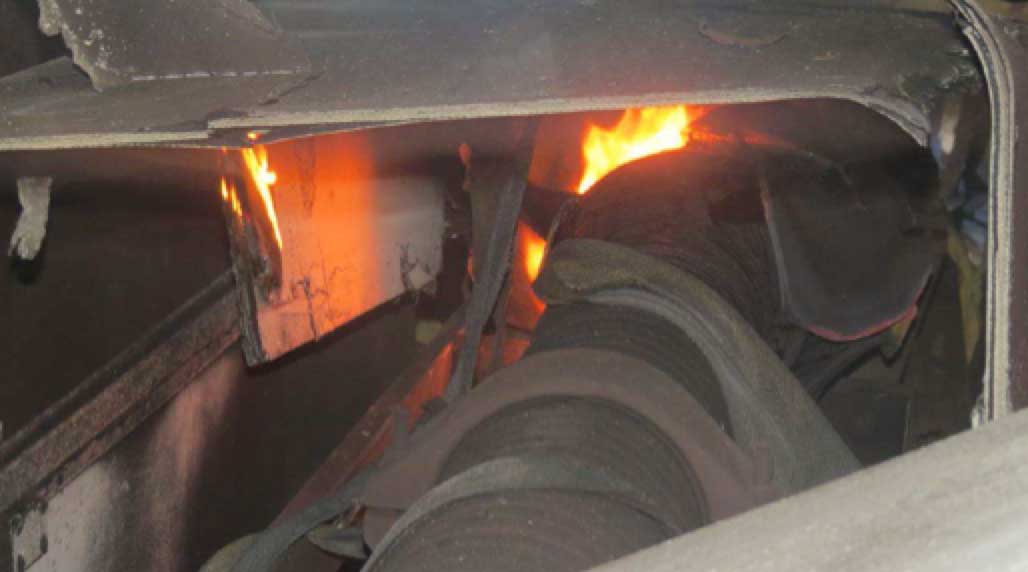
The most serious impact of a fault on a cable system was for the test assembly that included an installed joint. Indeed, when the faulted section is located in the joint (see Fig. 8 where a fuse nail is installed inside the joint), the amount of energy released is significantly higher than during other test scenarios and measured to be higher than 120 MJ. Given that joints are often the weakest component in a cable system, testing this layout configuration is seen as essential. In such cases, the resulting arc typically has a longer expansion path and much higher energy is released compared to other test simulations.
Other considerations apply to the complex structure of the joint itself, which consists of significant amounts of different materials bound together. As a result, an arc results in the most powerful shattering effect and a greater amount of flammable material is ignited, thereby contributing to fire propagation. Hence, whatever countermeasure is employed to suppress damage is exposed to the most critical scenario of collateral damage to the cable assembly. For example, in this case temperature in the tunnel rises to above 430°C and increases more rapidly than for other configurations tested, even with similar mitigation countermeasures. This is due to damage caused to the cable trough where the system is located. Fig. 9 offers evidence of the disastrous possible outcome in this test configuration.

Summary & Conclusions
As a result of developments in the energy market, large numbers of new T&D lines and substations will have to be installed and existing capacity will face upgrading. At the same time, continuing occurrence of major outages demands that more stringent safety and reliability regulations are implemented. These factors are forcing power utilities to look to testing as the most effective way to demonstrate that they exercise due diligence when choosing equipment and technologies. Moreover, construction of many new urban substations in major cities is also an issue and demand is growing to reduce their ‘footprints’.
Experience has recently been gained with internal arc tests on HV cable terminations and bushings, based on laboratory tests performed according to European technical specifications and standards. The risk of severe injury and long service interruptions in such critical conditions needs to be carefully considered and appropriate solutions adopted.
With particular reference to underground transmission cable systems, extensive testing has confirmed the possibility to contain the effects from an internal arc fault. For example, the possibility of a notable decrease in temperature distribution inside the tunnel has been determined, even given the same level of arc energy. In the case of the fault occurring inside a joint, which is generally the most frequent type of failure in such a network, energy released increases by about 40%. Use of specific countermeasures such as aramid band and a flame retardant FRP cable trough can help limit undesirable effects and also contain fire propagation. Today, appropriate laboratory testing makes it possible to simulate the effects of accidents in underground T&D networks and to implement appropriate countermeasures to reduce the associated risks.


References
[1] “10 Year Network Development Plan” ENTSO-E, 2012
[2] U. Vercellotti, A. Sironi “Safety issues in case of internal arc on HV cable terminations, bushings and surge arresters“, INMR World Congress September 2013, Vancouver CANADA
[3] U. Vercellotti, A. Fara, G. Miola “Fire risk analysis on MV cable networks: the behaviour of joints in case of fault“, Jicable 1995, Versailles, FRANCE
[4] O. Bosotti, W. Mosca, B. Cauzillo, L. Lagostena, F. Donazzi, R. Gaspari “Research on the performance of 400 kV extruded cable system under short circuit conditions”, CIGRE’ 1996, Paris, FRANCE