Application of 66 kV offshore inter array cables at wind farms are now in high demand. In modern submarine cables, there has been growing use of laminated aluminum in combination with copper wires as screen to replace traditional lead sheaths as water barrier. While this makes the cable more economical, the screen connection in cable accessories represents a challenge. This is especially so when it comes to direct grounding systems where it is important to consider circulating currents during normal operation as well as during abnormal operation, such as short circuits.
This edited contribution to INMR by Prof. Dr.-Ing. Klaus-Dieter Haim at the University of Applied Sciences in Zittau/Görlitz in Germany presents a survey of CIRED requirements for the test of cable screen connection for 66 kV offshore cables and normal 20 kV land cables. This will result in new proposals on how best to assess results and acceptance criteria as a first step toward a test standard for cable screen connections.

Up to now, there have not been major problems with the screen of medium voltage cables as well as with their connections to joints and terminations.
However, the issue of cable screen connections is becoming increasingly important for reliability of medium and high voltage cable systems due to increases in
• cross-section of cables;
• maximum conductor current and therefore increased screen current;
• failure rates of joints and terminations.
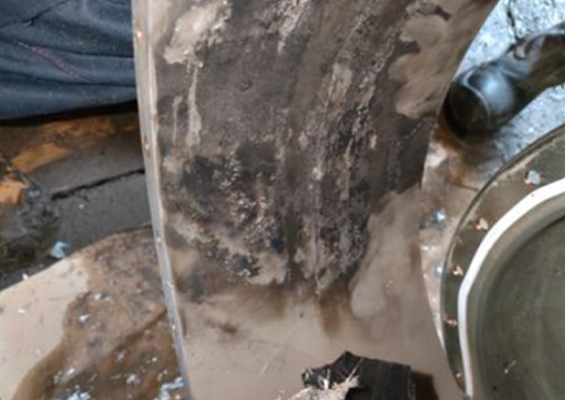
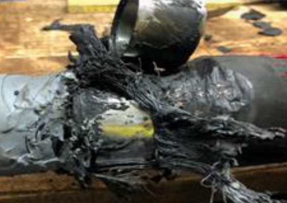
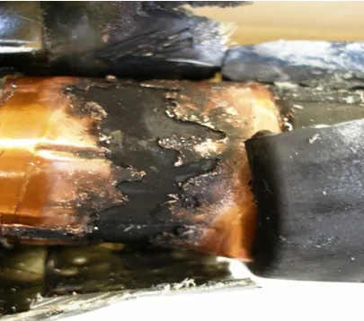
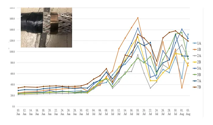
Use of full ampacity in cables in combination with increased cable cross-sections leads to higher conductor and screen currents. This is the reason for upcoming new problems, such as illustrated in Figs. 1 and 2.
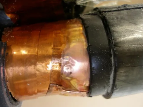
outer conductive layer by insufficient screen contact.

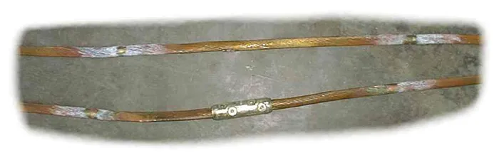
To avoid a rising number of joint failures of cable screen connections, CIRED Working Group WG 2017-1 has proposed procedures for testing and evaluating medium voltage power cables. But this recommendation is close to the connector standard (IEC 61238 -1-3) and only applies for cables with copper wire screen and direct connection of screen wires (as shown in Fig. 3) where such application is possible.
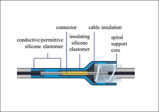
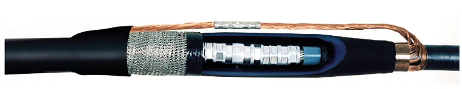
More than 95% of cable screen connections are not as presented in Fig. 3. Even for those cables with copper wire screen, use of modern all-in-one joints with incorporated screen contact systems (see Fig 4) requires a different screen contact solution for the joint.
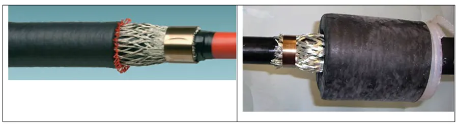
For all cables without a copper wire screen (i.e. more than 50% of MV cables), a special screen connection device is required. There are growing numbers of medium voltage cables with a laminated aluminum screen and, for this type, screen connection is more complex (see Fig 5).
Below is a discussion of the test procedure proposed as well as test results for 4 different cable screen connection designs of 66 kV separable plug-in terminations for offshore array cables. Also, results of tests on the 5 most often used screen connection designs for standard 20 kV cables. Based on these results, recommendations are given for modifying CIRED acceptance criteria.
Not all screen contact systems currently in use offer satisfactory long-term performance. The need to evaluate all the hundreds of various possible screen contact solutions requires a test procedure as well as assessment and evaluation criteria that are different from the connector standard.
Comparison of Conductor & Screen Connections
The test standard for MV cable conductor connectors (IEC 61238-1-3) is an internationally accepted test procedure and, with certain modifications, used worldwide. But for cable screen connections there is still no international standard available. The final report of the CIRED WG has been a first step in this direction.
The description of the test sample and test procedure is comparable with IEC 61238-1-3: 2018 and a good, practical approach. Assessment of test results and the acceptance criteria in the WG’s final report is also comparable to IEC 61238-1-3: 2018. This is a problem since the different physical behavior of cable conductor contacts and cable screen contacts requires a different evaluation of test results.
Fig. 6 shows the test set-up of a mechanical connector and the reference conductor without connector. A compression or shear bold connector generates high and permanent contact pressure. Measurements of contact resistance in a long-time test and load cycling over 1000 cycles show a stable contact resistance (see Fig. 7).
A cable screen contact, where the contact pressure is typically made by a constant force spring (see Fig 8) cannot generate high contact pressure. The results of contact resistance measurement are therefore not stable and that is why it is important to use different acceptance criteria for both contact systems.

Progress by CIRED WG 2017-1
This part presents laboratory test recommendations for MV cable screen connections according to the final report of the CIRED WG. The recommendation has its basis in the electrical part of IEC 61238-1-3.
This presentation is divided into 5 parts. The first describes how to determine the test current used in the heat cycles and short-circuit test. The second defines the test samples while the third covers resistance and temperature measurements. The fourth deals with the test program and finally, there is assessment of results and acceptance criteria.
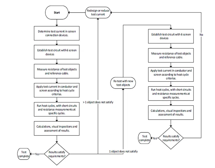
Flowchart Diagram for Testing
Fig. 9 shows a flowchart diagram for the test of screen connection devices.

Test Screen Currents
The screen current (INS) applied during the heat cycles shall be at least 20% higher than the maximum allowed screen current in the screen connection device during operation (IN), (INS ≥ 1.2 ∙ IN). The current shall be alternating at power frequency (50 or 60 Hz). If the test is performed for a specific application, IN can be determined prior to the test through simulations and/or trials. Minimum screen test current is 30A and the maximum can reach 360A, depending on operating current.
The screen current applied during short-circuit shall be equal to or higher than the maximum short circuit current the screen connection device will be subjected to during service. This can be chosen according to the CENELEC HD620 standard by which the cable screen has been tested.
Test Set-up
The screen connection devices shall be installed as specified in their respective assembly procedures. The assembly procedure used shall precisely indicate all assembly steps and tools, materials, tightening torques etc. Note that only the actual screen connection device needs to be installed in the test loop and not the complete joint or termination body. If the screen connection device is an integrated part of the joint or termination body these devices need to be included.
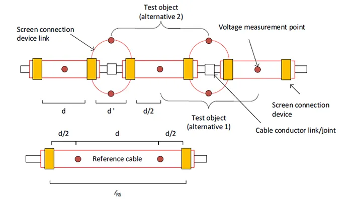
Test Objects
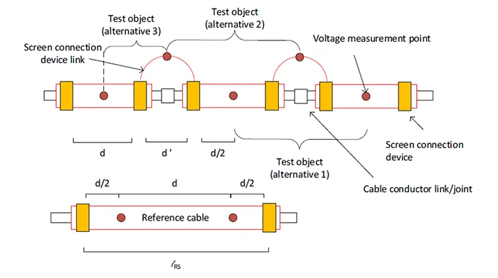
The test objects are defined between two voltage measurement points. The suitable measurement points will depend on how the metallic screen(s) and screen connection device(s) are constructed.
One of the three alternatives below shall be used:
1. Test object Alternative 1: Between the midpoint of two adjacent cables. This alternative can be used if the screen at the midpoint of the cables has an equalized contact surface, or if this can be made. The contact surface must be made accessible, such as by removing cable jacket.
2. Test object Alternative 2: At the midpoint of two screen connection device links. This alternative can be used if the screen connection device link has an equalized contact surface, or if this can be made.
3. Test object Alternative 3: Between the middle of two cable screen device links and midpoint of the cable. The number cables in the circuit may be reduced to ½ compared to the other two alternatives. This alternative can only be used for cable screens consisting of one metallic element, such as aluminium laminate, and where the screen connection device link has an equalized contact surface.
Fig. 10 presents design of a test cable with one screen, lengths and voltage measurement points while Fig. 11 shows this for cables with two or more screens.

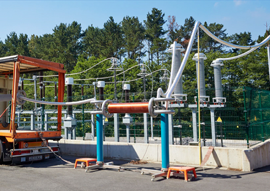
Test Circuits
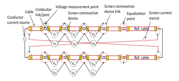
The test circuit (see Fig. 12) shall consist of six test objects, one reference cable and two different voltage sources. One for the screen current and one for the conductor current (nominal current of the cable).
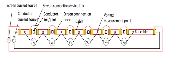
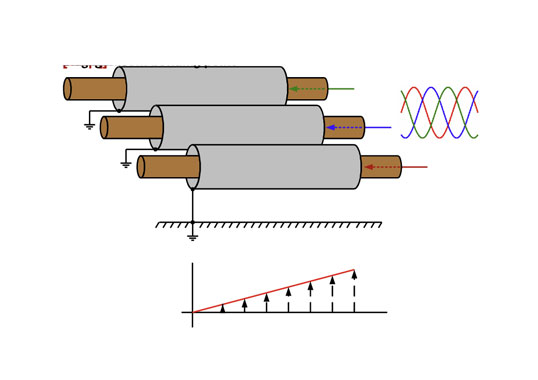
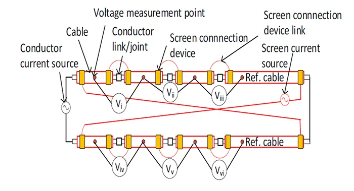
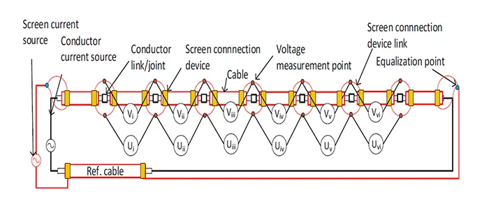
The resulting current through the screen is the combination of applied current by the screen current source and the induced current by the magnetic field generated by the current in the cable conductor. A cancellation of the induced current in the screen is possible by application of the test setup presented in Fig. 13. Figs. 14 and 15 shows the test set-up for cables with two or more screens.

Heat Cycle Test Program
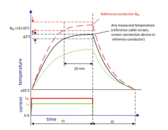
A current, INS, is applied to the screen and a current, INC, to the conductor. The purpose of INC is to add heat to the cable such that thermal equilibrium is reached at a higher temperature of the screen than INS would allow by itself. Heating duration is then set as the time required to reach thermal equilibrium, i.e., where none of the temperatures measured varies by more than 2°C during a 10 min period (see Fig. 16).
Short-Circuit Test Program
Two short-circuits shall be applied after the 150th heat cycle. The short-circuit shall be applied to the cable screen only. Screen connection resistance measurements shall be made before and after the two short-circuits (not between).
In the test report, the short-circuits shall be defined either by:
• Maximum temperature, time and approximate current; or
• Actual current and time and approximate maximum temperature.
Before each short circuit, the test loop shall have a temperature between 15 and 35°C.
Assessment & Acceptance Criteria
The design of test samples and the test procedure is a good start and can be a basic of a future test standard for cable screen connections.
The evaluation of the results is much more complex compared with the conductor connections and need more investigations and test experiences to fix final acceptance criteria.
Tests were started in 2014 at the University of Applied Sciences in Zittau involving 20 kV cable screen connections with much different contact designs, as supplied by a major cable accessory supplier. Additional tests were then done in 2021 on more samples (i.e. ALMA, ALINA,…), this time according to recommendations in the final report of CIRED WG 2017-1 and continued with more load cycling and resistance measurements. However, it has still not been possible to offer a definition of what constitutes a good versus a bad contact system for cable screen connections.

Conclusions & Recommendations
The different physical behaviour of cable conductor contacts and cable screen contacts makes it problematic to set up the same acceptance criteria for conductor connections and screen connections.
Considering the long-time measuring results of the screen contact resistance, a proposal for the resistance acceptance can be:
• Initial scatter δ should be maximum 0.5;
• Resistance factor change YA should be maximum 0.2;
• Resistance factor change YB should be maximum;
• Resistance factor ratio λ should be maximum 6.0
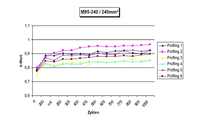
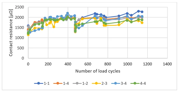
Results for two much different screen contact designs for 20 kV (see Fig. 17) and for 66 kV (see Fig. 18) make it clear that evaluation of a suitable test procedure for cable screen connections is far more difficult than for cable conductor connections.
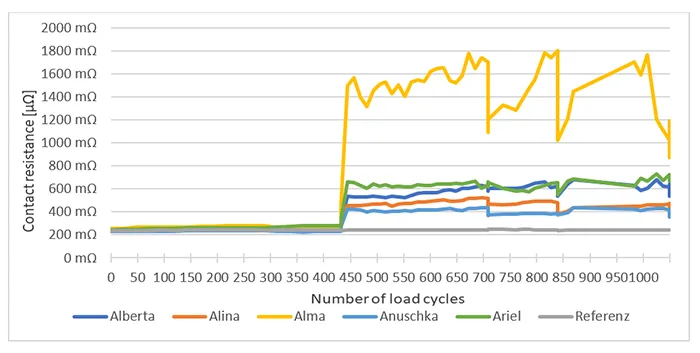
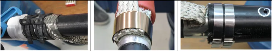
In Fig. 17 the yellow graph (screen connection with the name ALMA, see Fig 19) represents the most frequently used screen connection solution. This contact system cannot fulfil even the moderate requirement for the resistance factor ratio of λ = 6.0. This illustrates the challenges when it comes to setting evaluation and acceptance criteria for cable screen connection devices.
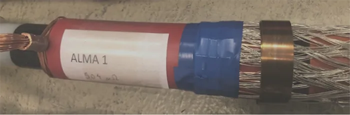
In the contact system, ALMA, the copper screen wires fold back on the cable sheath for a length of 5 cm. This area is covered by the copper mesh tube and the contact pressure is performed using a constant force spring.
References
[1] CIRED WG 2017-1 Final Report of the Working Group
[2] IEC, “61238-1-3: 2018,” in Compression and mechanical connectors for power cables – Part 1-3: Test methods and requirements for compression and mechanical connectors for power cables for rated voltages above 1 kV (Um = 1,2 kV) up to 30 kV (Um = 36 kV) tested on non-insulated conductors, ed, 2018.
[3] CENELEC, “HD620: Distribution cables with extruded insulation for rated voltages from 3,6/6 (7,2) kV up to and including 20,8/36 (42) kV,” ed