Pollution performance of insulator strings is key in design of towers for overhead lines and becomes even more pressing in the case of silicone surfaces whose hydrophobic properties are dynamic and can respond differently under varying service conditions.
This edited past contribution to INMR by Jean-Marie George and D. Lepley of Sediver offered observations and test details when evaluating performance of insulator strings under such conditions.

Solid Layer Pollution Testing with Heavy/Very Heavy Deposits on Silicone Surfaces
The hydrophobic property of silicone is highly desirable for polluted environments since hydrophobicity is transferred to the contamination layer and limits leakage currents despite surface deposits. However, the difficulty of testing such insulators lies in application of the deposit on their surfaces (as per CIGRE Technical Brochure No. 555, “Artificial pollution test for polymer insulators” Oct 2013), which has only been used for light and medium pollution classes. Moreover, another challenge has been deciding on the time required to allow for reasonable hydrophobicity transfer when heavy or very heavy pollution criteria are involved. Representativeness of the method may also need to be challenged.
The application process commonly used in such cases is to dip test insulators into a slurry adjusted for the desired values of ESDD. Most tests are performed at NSDD=0.1mg/cm² using correction factors to evaluate expected performance at higher NSDD values. The amount of deposits between top and bottom surfaces (i.e. the CUR ratio) is also usually taken at a standard value of 1.
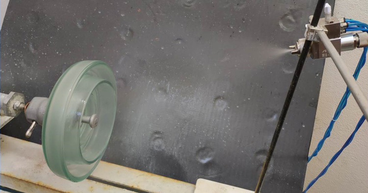
Sediver has developed a Spray Deposit Airborne Method (SDAM) by which the solid layer is built up on the insulator surface from airborne dust using a controlled spraying process – a method also mentioned in IEC 60507 (see Fig. 1). The SDAM allows for a deposit that is more representative of actual field conditions compared to dipping and also the possibility to achieve uneven CUR ratios. Unlike for dipping, where thickness is often non-homogeneous, the SDAM ensures a high level of homogeneity all along the surface.

Whether by dipping or using the SDAM, there still remains the question of selecting optimal transfer time prior to testing when the layers correspond to either heavy or very heavy pollution (i.e. where NSDD level exceeds 0.2mg/cm²). Although accepted practice today is to wait 48 or 72 hours between application and the pollution test, in the case of very heavy conditions the transfer may not yet all be in place in such time frames.
Fig. 2 shows average transfer time under heavy pollution conditions. In fact, the real question is deciding between a standard ‘rest time’ or some defined hydrophobicity status. Most likely, an HTM insulator does not need to be HC1 (the most hydrophobic state) to perform well. But in that case what is acceptable given that insulators can actually have hydrophobicity levels that are not uniform along their entire surface and also not uniform along the entire string (or unit of a polymeric long rod)?
Clearly, this issue needs to be addressed by the experts involved in future standardization work, keeping in mind that in the real world such levels do not accumulate at once but rather progressively. Low molecular weight species (LMW) within the silicone bulk rubber material need time to migrate fully through the contamination deposit and this is different from an artificial test where the entire pollution layer is applied in a single operation.

Fig. 3 highlights the difference in transfer time between a dip type deposit and an SDAM type deposit. Because under natural conditions deposits are airborne, it is interesting to note that while the SDAM is more representative it leads to different dynamics in transfer of the LMW species. These findings open the question of practicality when testing for very heavily polluted conditions. For example, it can be noted that transfer time varies not only with chemistry of the silicone material but also with temperature to which the test samples are subjected after application of the pollution layer.
Rapid Flashover Method
The commonly used rapid flashover method offers valuable acceleration when evaluating performance of a given string of insulators. Nonetheless, experience in pollution testing has demonstrated the need to produce a withstand test around the values obtained in the rapid flashover method so as to validate maximum withstand. Typically, this will be higher than any calculated value based on the rapid flashover method.
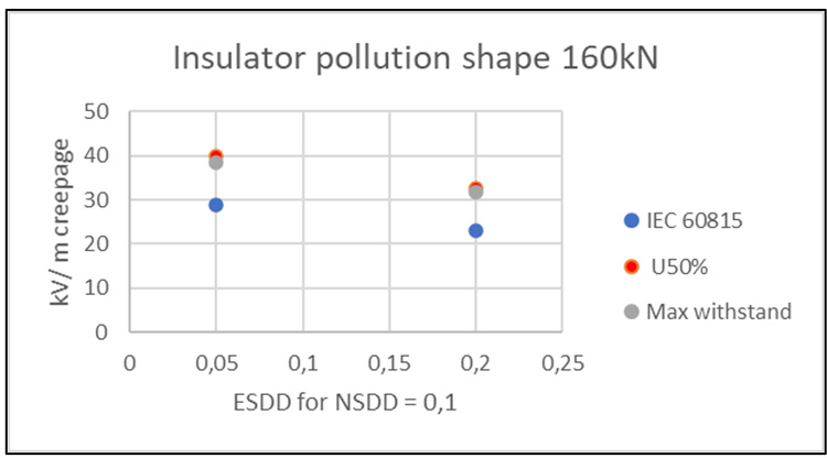
As shown in Fig. 4, actual withstand is close to the value calculated as per IEC Standard 61245 (“Artificial pollution tests on high-voltage ceramic and glass insulators to be used on d.c. systems”, Edition 2.0, 2015-03) taking the average between highest withstand and lowest flashover result from the up-and-down method.

Pollution Performance Under DC Voltage
HVDC lines are typically used for long interconnections between remote generation sites (e.g. hydraulic, renewables) and major demand centers located far away. Built in Europe since the 1960s, such links have more recently been constructed in North America, Brazil, Africa, India and China.
Apart from the specificities required in insulator design to cope with a unidirectional electric field, pollution is usually the main factor when dimensioning insulator strings for these lines. In recent years, theoretical models and equations have been created to assist in this task, leading to the recommendations found in IEC TS60815-4.
However, definitions of required USCD as a function of pollution conditions, as described in this Guide, are regarded (by the contributors) as overly pessimistic for glass or porcelain insulators and overly optimistic for polymers. (The contributors feel) that the USCD requirements for ceramic insulators need to be revised and especially so for toughened glass whose performance (they argue) is more than 30% better than the IEC curve. The contributors also propose that some safety buffer needs to be included against risk of early erosion for polymers when design focuses strictly on pollution performance and not on avoiding premature ageing.
The basis for the above lies in an exhaustive test program conducted at Sediver’s DC pollution laboratory involving different levels of solid layer pollution. Fig. 5 from this research shows the gap between actual performance of a typical fog type glass insulator versus the USCD curve required as per IEC (the dotted line).
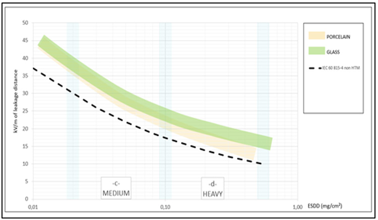
These results were then calibrated against a reference pollution test performed at an independent international laboratory. This data corresponds to tests performed on insulators that are characterized by a shape specific to DC application.
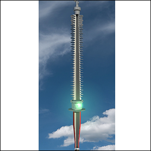
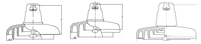
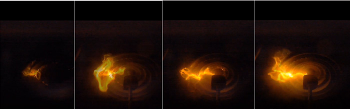
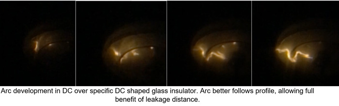
Dry band arcing activity in DC is different from AC and therefore insulators specific to DC application (the only ones to consider when describing DC pollution performance) are designed with relatively large inter-rib distances and at least one long rib (see Fig. 6). This mitigates arc development, as shown in Fig. 7 using a high-speed camera. It can also be noted that the manufacturing process for glass insulators allows for a better profile than is the case porcelain (i.e. longer ribs and typically one less rib for an identical leakage distance). This is also seen from Fig. 5.
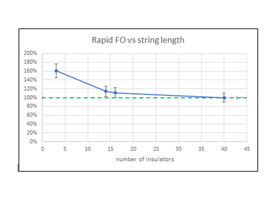
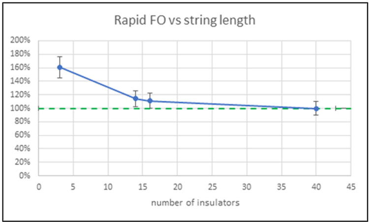
It is interesting to also note that a similar test was performed with various lengths of strings. Laboratories with limited testing resources would establish DC performance based on short strings and extrapolate to longer strings. But it has been shown in this research program that a test performed on only a few units (e.g. 3 to 5) is overly optimistic compared to longer strings. Rather, it seems that a minimum string length of 3 m is required to obtain a truly representative test result that can then be safely extrapolated to longer strings. For example, performance of a typical 500 kV string can be established using a half string sample. Fig. 8 shows a summary of the test program performed at three laboratories.

Conclusions
Work is needed to establish broadly acceptable test techniques that define performance under solid layer pollution conditions for insulators made with hydrophobic surfaces. This is even more the case when pollution levels are heavy or very heavy.
Actual pollution performance may need to be challenged to avoid excessive string lengths, especially in DC. Moreover, the data used in theoretical evaluation of USCD needs to focus on specific DC insulator designs.
Insulator profile matters greatly in DC and generic performance curves can be misleading when disconnected from the proper product characteristics. In this regard, it is worrisome to see DC projects in which shape is ignored and offers are submitted based on classical AC insulator design. This technical aspect should be kept in mind, with opportunities for string optimization made possible through laboratory testing.
References
[1] IEC Standard 60507, “Artificial pollution tests on high-voltage ceramic and glass insulators to be used on a.c. systems”, Edition 3.0, 2013-12
[2] IEC Standard 61245, “Artificial pollution tests on high-voltage ceramic and glass insulators to be used on d.c. systems”, Edition 2.0, 2015-03
[3] IEC/TS 60815-4, “Selection and dimensioning of high-voltage insulators for polluted conditions – Part 4: Insulators for d.c. systems”, Edition 1.0, 2016-10
[4] CIGRE Technical Brochure No. 555, “Artificial pollution test for polymer insulators”, October 2013
[5] I. Gutman, J. Shamsujjoha, C. Lumb, J.M. George, S. Roude “Modern Investigation of Rapid Flashover Solid Layer Pollution Testing Methods as an Alternative to Current Standard Diagnostic”2012 IEEE
[6] A Pigini, “Design and testing of polymeric insulators to verify the pollution
performance under dc voltage” 2015 INMR WORLD CONGRESS.
[7] JM. George E. Brocard, D. Lepley, F. Virlogeux, Sediver. “Correlation assessment
between actual pollution performance of insulator strings in DC and theoretical
models”13th INSUCON Conference, Birmingham, UK 2017
[8] JM. George Sediver “Insulator contamination assessment and mitigation for AC and
DC overhead lines”. CIGRE USA symposium 2018 Grid of the future.
[9] Gutman et all: State of the art of pollution test procedures for insulators with
Hydrophobicity transfer materials. CSE N°21 June 2021
[10] NGK release N°101/1982 DC fog suspension insulators
[11] SEDIVER DC insulators catalog