Several decades experience testing components for medium, high and ultra-high power networks offer valuable insight into issues of quality and performance.
This edited past contribution to INMR by Bas Verhoeven of Kema Labs in the Netherlands reviewed findings based on 30 years testing cables and accessories.
Cables: Type, Pre-qualification & Commission Testing
International standards for testing at medium, high and ultra-high voltages include 3 distinct groups of tests. The first is type testing intended to verify design and manufacturing. Testing a cable system comprised of the cable and accessories such as joints and terminations (open-air, SF6 or oil plug-in) takes place in a laboratory with various electrical tests followed by heat cycle tests that simulate the loading pattern under normal use. Testing non-electrical properties of cable materials is also part of a type test.
The second group – pre-qualification testing – is only applicable to high and ultra-high voltage cables. After successful completion of type testing, the cable is installed under realistic outdoor conditions that mimic normal installation methods, including being buried directly in the ground and with some sections installed in tunnels. A voltage of 1.7 Uo is applied to the cable and 180 heating cycles are applied, one every 2 days. A pre-qualification test lasts one year.

The third group is commissioning testing of a newly installed cable system. After installation in the field, the cable is energized to e.g. 1.7 Uo for one hour to detect possible errors in workmanship.
The relevant IEC standards for AC cables are:
• IEC 60502-2 for Cable 6kV–30kV
• IEC 60502-4 for Cable Accessories 6kV–30kV
• IEC 60840 for Cable & Accessories 30kV–150kV
• IEC 62067 for Cable & Accessories 150kV–500kV
STL Guides in regard to IEC 60840 and 62067 were issued in 2019 with the goal of harmonizing interpretation and execution of these standards, with focus on pre-qualification tests.
Although international standardization for DC cables is less developed than for AC cables, these types of cable have specific test requirements for the temperature gradient over the XPLE-insulation material and a superimposed DC and LI test. Current standards for DC cables include:
• CIGRE 496
• IEC 62895:2017

Failure Statistics from Type Testing Cables
Manufacturers come to test laboratories such as Kema Labs for a formal type test once they believe their products meet all the requirements set out in the standards. However data on intial failure rate when entering into a type test program, based on more than 1000 cables and accessories tested, indicates a failure rate of about 25%.
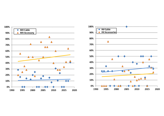
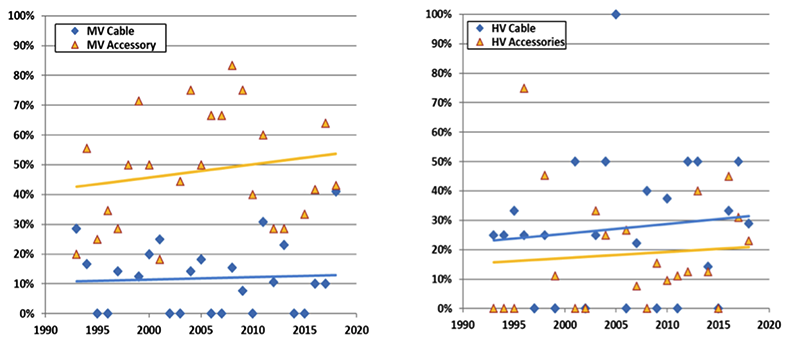
Fig. 1 shows failure rate for medium voltage cables and accessories as well as these in the case of high and ultra-high voltages combined. Medium voltage terminations and joints show a high failure rate, due mainly to improper materials used in the heat shrink technology. Moreover, high voltage cables tend to show a higher failure rate compared to the medium voltages. This is because MV cable manufacturers try to enter the HV market due to potentially higher profit margins but often face manufacturing quality issues at higher voltages.
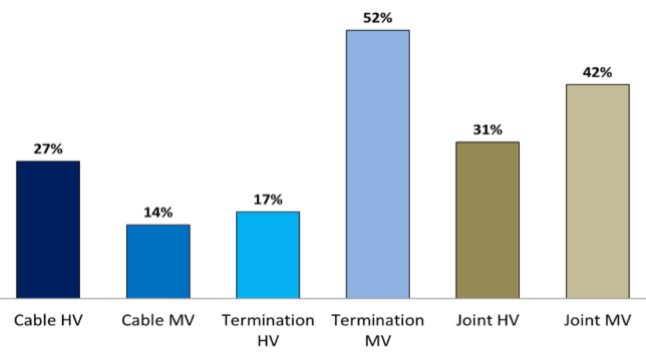
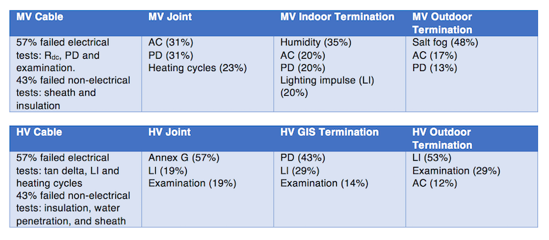
Fig. 2 shows year-on-year initial failure rate for MV and HV cables and accessories. Straight trend lines all have a positive inclination indicating that initial failure rate is increasing over time instead of the normal expectation of decreasing due to improved technology, experience and skill. This increase is likely the outcome of huge market pressure on lowering cost, which risks affecting quality of cables and accessories and eventually resulting in more network blackouts.
Failure modes of cables and accessories vary depending on voltage class and Table 1 provides an overview for both MV and HV.
Newly installed XLPE cables require a commissioning test to verify correct installation before a cable system is connected to the main network. The best way to conduct such a test is application of voltage above nominal system voltage that is maintained for a certain period of time.
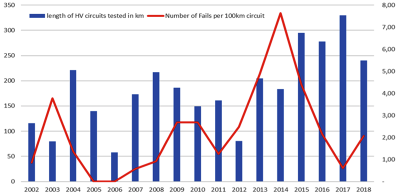
For example, the IEC standard recommends 1.7 Uo for one hour. KEMA Labs has tested many newly installed cable systems across Central Europe and Fig. 3 shows the total circuit length of cable tested per year. The red line represents number of breakdowns normalized per 100 km of installed cable circuit. While the long-term average should be only 2 failures per 100 km installed circuit length, there is a peak of nearly 8 breakdowns per 100 km circuit length. This was found to have been caused by improper cable jointing in projects where there was great pressure to complete and energize the circuit. A secondary reason was hiring of insufficiently qualified jointers.

Statistics on Installed Cable Failure Analysis
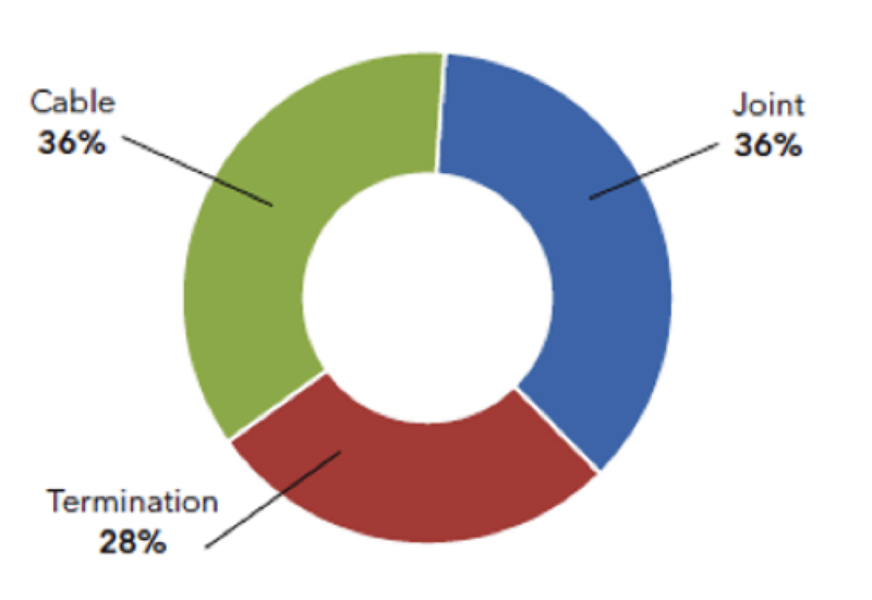
Kema Labs also conduct independent power failure investigations (PFI) of in-service cable systems. Fig. 4 shows that the root cause of failures in over 225 of these PFIs is almost equally distributed between the cable, the joints and the terminations. Root cause failure modes for cables were:
• 33% production related;
• 19% installation related;
• 17% due to external damage; and
• 11% due to design issues.
For joints and terminations, root causes of failures were:
• 57% installation related;
• 13% design related; and
• 8% production related.
Design issues as the root cause of failures in any PFI of in-service cables and accessories are surprisingly high and lead to the question whether these components have been certified. Since the reply is almost always “yes”, it becomes clear that the certification process may not always be sufficiently transparent. By contrast, data also shows that components tested in an independent laboratory do not show such a high proportion of design related root cause of failures.

Pressure Relief Test for Surge Arresters
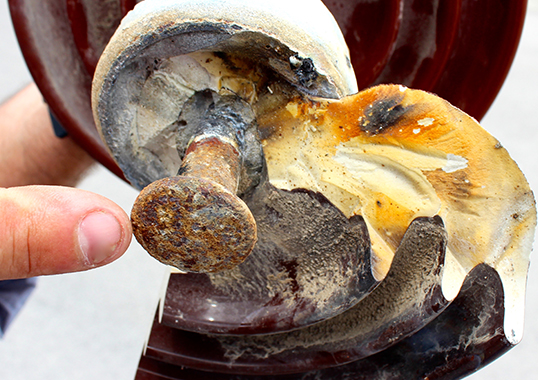
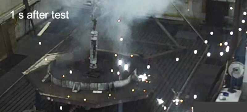
The pressure relief test is important for surge arresters. In case the energy dissipation is too high, due to ageing related or other defects, the arrester can explode and eject debris into the surroundings. Debris can damage nearby equipment resulting in potential loss of a substation bay. Standards include a pressure relief test to determine if debris is not ejected beyond a radius of 3m.
Data from pressure relief tests conducted as part of type testing arresters indicate that approximately 25% do not meet the standard. Fig. 5 for example shows debris one second after the pressure relief test. Many large hot particles can been seen well beyond the maximum permitted 3m radius.
It has become common practice in many countries for surge arresters to remain in service until failure. But such failure of an arrester basically can result in an explosion within the substation. It is therefore important to ensure that only surge arresters that have been properly certified to meet this standard are kept in service.