Tracking and erosion resistance is one of the key properties of polymeric materials for high voltage outdoor applications and was standardized decades ago for AC stress using the inclined plane test (IPT) as per IEC 60587.
Collecting experience with DC stress began some 25 years ago. The common result of all these investigations was: if identical test parameters for both AC and DC are chosen, DC stress leads to more intense tracking and erosion than at AC, especially so if the positive polarity is used during testing.
This higher severity can result in too harsh a testing of investigated materials and their disqualification, in a non-differentiable manner, which often contrasts to actual service performance. Therefore, various modifications of test parameters such as reduction in test voltage or flow rate have been conducted to decrease test severity and evaluate and differentiate between materials.
This edited past contribution to INMR by C. Baer, J. Lambrecht and K. Hindelang of Wacker Chemie in Germany reported on past research comparing erosion resistance of silicone rubber materials under DC stress.


Past work within CIGRE WG D1.72 has concentrated on basic investigations with the IPT to develop a standardizable test method in IEC with respect to representativeness, repeatability, reproducibility and cost efficiency.
The general aim of the IPT is an accelerated testing of tracking and erosion resistance by continuous discharge activity. Under AC, test parameters, i.e. voltage, flow rate and series resistance, are set such that continuous discharge activity is achieved. Such parameter studies have so far been missing for DC application. Afterwards, parameters for DC set-up were defined during pre-investigation such that continuous discharge activity was achieved and overly severe test conditions were prevented.
In case of severe erosion, formation of degradation products can influence test conditions by interrupting continuous discharge activity. This is not desirable.
Two round robin tests with constant voltage, one at 4.5 kV DC and another at 3.5 kV DC, both at positive polarity, using one silicone elastomer formulation were conducted at 7 test laboratories.
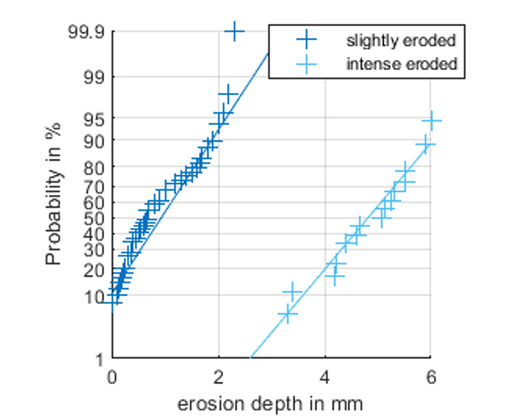
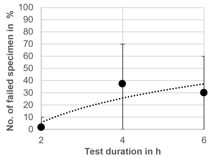
It was observed that test results between different laboratories but also within one test series show a wide spreading of the results from passing the test with slight erosion only or failing by digging erosion and hole formation. Thus, a statistical evaluation showed a mixed distribution as shown for the maximum erosion depth in Fig. 1. Further analysis showed that the degradation process is non-linear with time and is accelerated once digging erosion was initiated. Therefore, further tests were conducted with reduced test durations of 2 h and 4 h (Fig. 2) and it could be shown that most specimens fail between 2 h and 4 h of the test time. Thus, testing with application of constant voltage was found to be unsuitable for an international material testing standard.
To reduce the scatter and to avoid the occurrence of a mixed distribution of test results, a stepwise increase of the test severity was thought to be advantageous in evaluating and ranking different materials under DC voltage stress. Therefore, the aim of this contribution is an evaluation of the DC tracking and erosion resistance of different silicone elastomer formulations by using a stepwise increase of the test voltage. Results are compared with investigations conducted under AC stress according to IEC 60587. For a stepwise increase of the test voltage, a utility step-test specification with up to seven voltage levels is taken. Furthermore, a simplified method with three voltage levels only is applied.

Test Methods & Procedures
Additional tests under DC voltage of positive and negative polarity involving different silicone elastomers were conducted according to the following parameters:
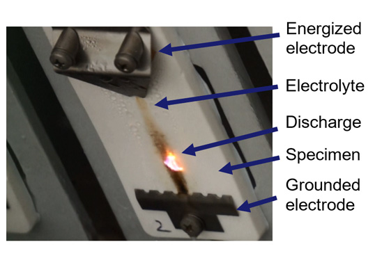
• Test setup and test parameters according to IEC 60587 (see Fig. 3);
• Flow rate of 0.3 ml/min for any voltage level
and procedures:
• Stepwise increase in test voltage in seven steps, starting from 2.15 kV DC+ and increasing every 60 min for 0.25 kV until 420 min of test duration (10 samples per material formulation);
• Stepwise increase in test voltage in seven steps, starting from 2.90 kV DC- and increasing every 60 min for 0.25 kV until 420 min of test duration (10 samples per material formulation);
• Stepwise increase in test voltage in three steps, starting from 2.45 kV DC+ and increasing every 120 min for 0.5 kV until 360 min of test duration (5 samples per material formulation).
As reference, an AC test was carried out with constant voltage application at 4.5 kV for a maximum of 360 min with parameter selection according to IEC 60587. This was done for the material formulations chosen as well (i.e. 5 specimens per material formulation).

As reference, an AC test was carried out with constant voltage application at 4.5 kV for a maximum of 360 min with parameter selection according to IEC 60587. This was done for the material formulations chosen as well (i.e. 5 specimens per material formulation).
Table 1 shows the different silicone elastomer formulations tested (VMQ, vinyl-methyl silicone elastomer).
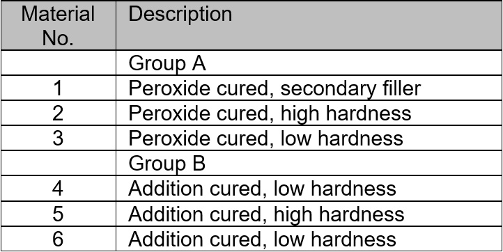
Materials have been selected such, that the erosion resistance is weakening within the groups A and B, from material VMQ 1 towards VMQ 3 and VMQ 4 towards VMQ 6 each.
So, while VMQ 1 and VMQ 4 are established material formulations with a good resistance to tracking and erosion and positive long-term service experience, VMQ 2 and VMQ 3 as well as VMQ 5 and VMQ 6 are modified variants with high and low hardness of peroxidic respectively addition curing systems and have been created for these investigations only.
A voltage level counts as passed if the leakage current does not exceed 60 mA for 2 s, no deep erosion with formation of a hole occurs, and samples don’t start burning.
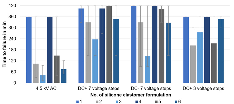
For a better comparison of the tested materials, the time to failure, the mass loss and the maximum erosion depth have been measured. Since silicone elastomers don’t show typical tracking characteristics but erosion, it was decided not to evaluate their track length.

Test Results for Silicone Elastomer Formulations Investigated
Reference results (4.5 kV AC stress acc. to IEC 60587) and results of all DC step tests are presented and discussed in the following:
• time to failure (see Fig. 4);
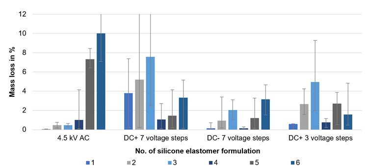
• mass loss (see Fig. 5);
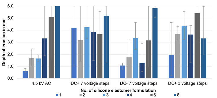
• maximum erosion depth (see Fig. 6).
Evaluation of AC Test Results
As expected, at 4.5 kV AC, VMQ 1 and VMQ 4 pass the tracking and erosion test by showing low average values of the mass loss and moderate values for the maximum erosion depth. These materials are classified as tracking and erosion resistant with class 1A4,5.
In comparison to these results, the other material formulations do not pass the 4.5 kV AC tracking and erosion test and fail at least for one sample by exceeding the leakage current criterion with a switch-off before the full test duration of 360 min is reached. Additionally, VMQ 5 and VMQ 6 show severe erosion with a high mass loss and formation of a hole.
Evaluation of DC Test Results
Under DC voltage, most of the materials show more severe erosion for the chosen test procedures compared to tests at AC voltage.
By comparing the three different DC test procedures, the procedure with seven different voltage levels with positive voltage results in the most severe erosion, followed by testing with three voltage levels at positive DC voltage stress. The conducted tests under negative DC show less severe erosive degradation than the tests at positive polarity, which is consistent with previous investigations [8].
The test procedure with three voltage steps at positive polarity was conducted in the attempt to reduce the required test effort, the test severity, and the spread of the test results. This was achieved for the majority of the tested material versions and allows a better differentiability between the tested materials.
Although the silicone elastomer formulations do not exactly show the same performance and ranking compared to AC voltage, both VMQ 1 and VMQ 4 show the highest time to failure, lowest mass loss and lowest maximum erosion depth within their material groups, especially with respect to the DC step test with 3 steps.
Material formulations VMQ 5 and VMQ 6 show a quite different performance at AC and DC stress. While both materials perform quite poor under AC stress with respect to the mass loss and the maximum erosion depth, they show a better performance under DC stress, also compared to VMQ 2 and VMQ 3. The root cause for this is not clear yet and needs to be further investigated to avoid improper material selection

Summary & Conclusions
As a conclusion from the conducted investigations, and in line with previous investigations, a separate DC tracking and erosion test is seen to be required to properly select and rank materials for high-voltage DC outdoor application since test results conducted under AC stress cannot be transferred to DC application.
As it could be observed in recent CIGRE WG D1.72 activity with a high scatter of test results within one test series in one but also between different laboratories, the current approach with constant voltage application is not seen to be sufficient and satisfying to fulfil the requirements to become a standardised IEC test method.
A potential solution is seen in the application of a stepwise voltage increase which increases the test severity during testing and shall reduce the high test scatter. In this contribution, three different test procedures for a stepwise increase of a DC test voltage of both polarities were presented. While testing with seven voltage levels at positive DC voltage resulted in the most severe erosion during these investigations, much less severe erosion was observed for the negative polarity. From this perspective, it is concluded that testing with negative polarity may not be required and testing at positive polarity only may be sufficient, which is consistent with previous investigations.
It could be shown furthermore that testing with three DC voltage levels and positive polarity reduces the test effort, test severity, the scatter of test results and may therefore allow a differentiation and ranking between investigated material formulations.
Further work basing on a stepwise increase of the DC test voltage as presented in this paper is planned in a future CIGRE D1 WG including international round robin testing and finally preparing a recommendation for an internationally standardized test method in IEC.

References
[1] IEC TR 62039:2021 – Selection guide for polymeric materials for outdoor use under HV stress, March 2007.
[2] IEC 60587:2007 – Electrical insulating materials used under severe ambient conditions – Test methods for evaluating resistance to tracking and erosion, Mai 2007.
[3] G. P. Bruce, S. M. Rowland, A. Krivda: “Performance of Silicone Rubber in DC Inclined Plane Tracking Tests”, IEEE TDEI, Vol. 17, No. 2, pp. 521-532, 2010.
[4] C. Bär, R. Cervinka et al.: “On a Comparative Evaluation of the Retention of the Hydrophobicity and the Tracking Resistance of Silicone Elastomers under AC and DC Stresses”, 17th International Symposium on High Voltage Engineering, Hannover, 22nd -26th of Au-gust 2011.
[5] R. A. Ghunem, S.H. Jayaram, E.A. Cherney, “Inclined Plane Initial Tracking Voltage for AC, +DC and –DC”, Conf. Record of the 2012 IEEE Int’l. Sympos. Electr. Insul. (ISEI), pp. 459-463, 2012.
[6] J. V. Vas, B. Venkatesulu, M. J. Thomas: “Tracking and Erosion of Silicone Rubber Nanocomposites under DC Voltages of both Polarities”, IEEE TDEI, Vol. 19, No. 1, pp. 91-98, 2012.
[7] R. A. Ghunem, S. H. Jayaram and E. A. Cherney, “Erosion of Silicone Rubber Composites in the AC and DC Inclined Plane Tests”, IEEE Trans. Dielectr. Electr. Insul., Vol. 20, No. 1, pp. 229- 236, 2013.
[8] CIGRE WG D 1.27, TB 611: “Feasibility Study for a DC Tracking and Erosion Test“, 2015.
[9] DLT 810-2002 – Technical specification for ± 500 kV D.C long rod composite insulators, 2002-09-01.
[10] “IEEE Guide for DC Inclined Plane Tracking and Erosion Test for Outdoor Insulation Applications,” in IEEE Std 2652-2021, vol., no., pp.1-22, 7th of October 2021
[11] S. Kuehnel, S. Kornhuber, J. Lambrecht, K. Hindelang: Evaluation of the Tracking and Erosion Resistance at DC-Stress using the Example of Silicone Elastomers, 8th Conference on Silicone Insulation, Burghausen, Germany, 2022.