One of the important design differences between composite insulators and porcelain or glass cap & pin types is smaller shank diameter, made possible by the high strength glass-fibre reinforced core rod. However, slimmer profile also means smaller metal end fittings and the issue of corona must be addressed, even at lower voltage levels.
As far back as 1992, CIGRE provided a general recommendation that, starting from 220 kV, application of a suitable corona ring on the HV side is necessary – mainly because of potential impact on RIV. Subsequently, specialized software has become available to accurately simulate how corona can affect critical areas of a composite insulator, such as the triple point, as well as the effect of water droplet corona.


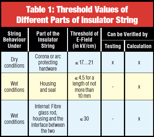
In 2008, the IEEE Taskforce on Electric Fields and Composite Insulators published a paper summarizing the state-of-the-art in this critical area and which highlighted corona protection designs proposed by different manufacturers, depending on voltage rating. It also showed possible installation faults and advised on modelling electric field as well as differentiated between field intensities that influence insulator string behaviour under dry as well as wet conditions (water droplet corona phenomenon). Three important thresholds (shown as rms values) were mentioned in this document, and these must not be exceeded when the insulator string is being simulated under dry conditions with no pollution (see Table 1). Impact of air density also must be considered in case of installation at altitudes significantly higher than sea level. Local rules typically provide the necessary correction factors in such cases.
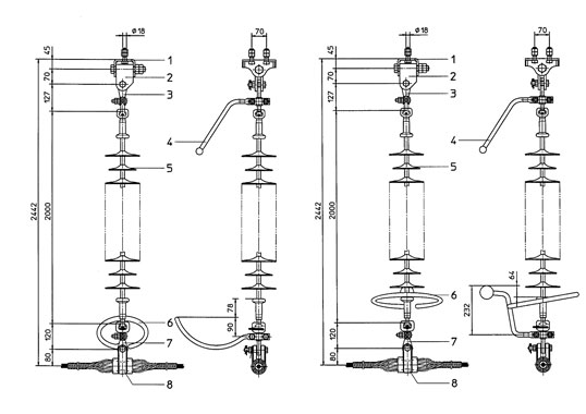
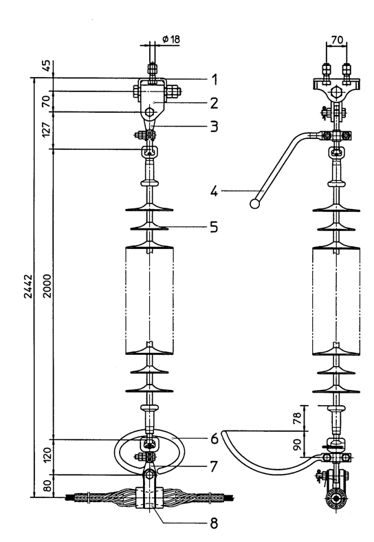
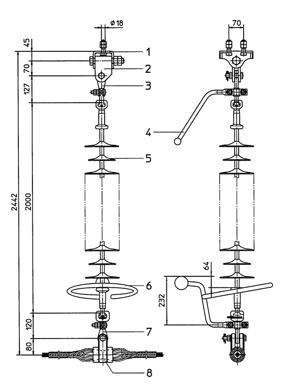
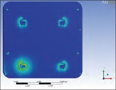
In 2005, CIGRE WG B2.03 published Technical Brochure 284 titled Use of Corona Rings to Control the Electrical Field along Transmission Line Composite Insulators. Various 2-D and 3-D simulation programs were investigated that use finite element or boundary element methods. Comparison of results has shown that, if correctly used, these programs provide similar results. An interesting approach was adopted during this work involving 3-D simulations on two different types of 245 kV insulators (see Figs. 1a and b).
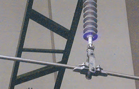
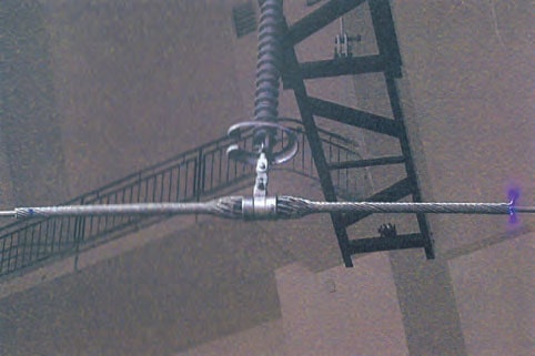
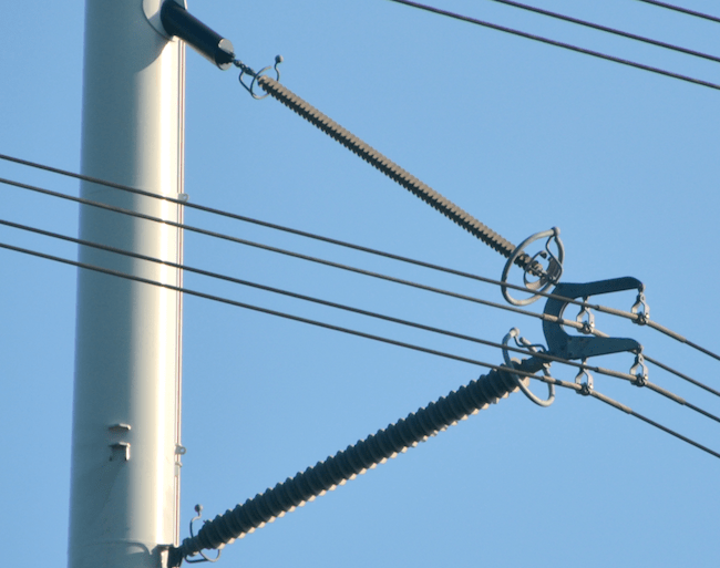
Laboratory tests were then conducted to measure the corona inception and extinction voltages on their HV end fittings in order to verify the simulations. Tests were performed at two different laboratories with the test configuration kept constant for each, i.e. same conductor, conductor clamp, height above ground, distance to steel cross-arm (see Figs. 2a and b).
This experimental configuration was also modelled using 3-D simulations of E-field. The voltage at which the electric field at the most exposed portion of the HV end fitting reached 22 kVrms/cm was then referred to as ‘calculated corona threshold voltage’ (see Table 2)
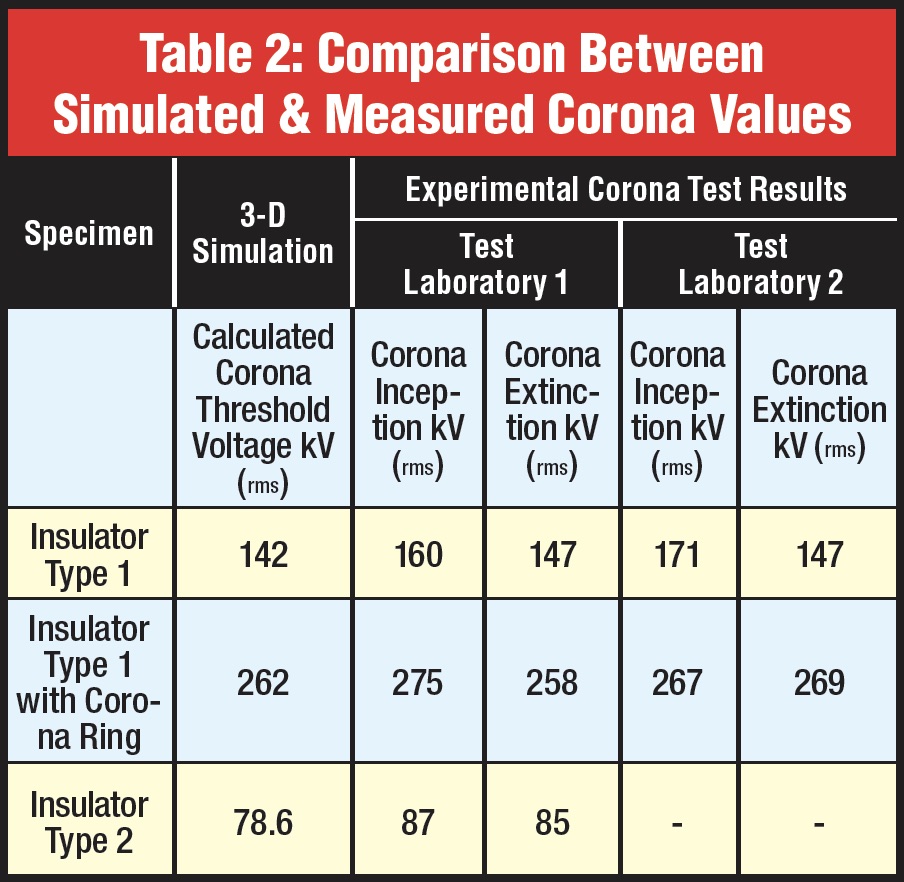
Comparing calculated corona threshold with corona extinction voltages measured at the two laboratories, it was observed that the difference between measured and simulated values was less than 10% of the minimum value for Insulator Type 2 and even lower for Insulator Type 1. Moreover, the differences were such that, in all cases, the simulation tended toward lower values. Hence, if anything, simulated results were always on the ‘safe’ side when it comes to design margins.
For example, Wintrack in the Netherlands – an innovative 420 kV compact double circuit line design – had to meet stringent values of acceptable electromagnetic field stress. This meant that for the composite insulators selected permitted threshold of electric field was even lower than that specified from common practice in the U.S. To verify this, simulations were performed using finite element and boundary element methods and included modelling the neighbouring phases, insulators, hardware and conductors (e.g. see FEM simulation in Fig. 3). These simulation models showed that neighbouring phases cause electric field to increase by about 10%, which then has to be taken into account when designing combined corona and power arc protection devices. Finally, after demonstration that all these required values were fulfilled and that the protection devices also met aesthetic demands, full testing was completed.
The phenomenon of corona on composite insulators has since been well documented. With progress in computer performance as well as availability of new software programs, associated electric field stress on an insulator can be calculated, even after taking overall structure near the string into account. Analysis of field data has also confirmed that empirically determined thresholds can be deduced from long-term experience. Still, care must be taken whenever new designs are developed or when there are innovative packages that combine new string hardware and insulators. Since cost is now a driving factor in line construction, design engineers must be aware that too great an emphasis on economics risks under-dimensioned components that may have reduced service lives.