Increased penetration of Distributed Generation (DG) from solar and wind plants has created challenges for network operators when it comes to power quality issues such as voltage regulation, power factor and harmonics. If DG sites do not comply with grid connection requirements, there may be a need to install power quality improvement equipment. In those cases where DG sites require reactive power and voltage support, capacitor banks are the most cost-effective solution. However, switching of capacitor banks can introduce voltage disturbances at the connection point due to the possibility of high magnitude inrush currents.
Recent improvements, such as controlled switching technologies, have allowed minimizing inrush currents during energization and also fast switching of capacitor banks. These developments have increased the viability of capacitor banks in applications where a STATCOM solution used to be required. But capacitor bank switching requires special attention because of the possibility of a restrike after current interruption. Many high voltage SF6 and vacuum circuit breakers are designed for capacitive current switching. However, unpredictable or unavoidable restrike phenomena still occur. If a CB restrike does occur, this leads to high frequency and high magnitude overvoltages, large inrush currents and also large outrush currents in the case of back-to-back capacitor bank switching. Consequently, a restrike can induce additional stress on capacitors, de-tuning reactors and CBs, possibly leading to catastrophic damage. One mitigation measure to maintain restrike overvoltages at permissible and safe levels involves implementing surge arresters across the capacitors. Installation of arresters also minimizes probability of restrike, especially of multiple restrikes.
This edited past contribution to INMR by Tim Rastall and Kerim Ozer of Enspec Power in the United Kingdom discussed application of surge arresters for mitigation of overvoltages on MV & HV capacitors based on single restrike. Two particular capacitor bank designs were investigated: a 33 kV, 50 Hz ungrounded double wye connected bank and a same size de-tuned bank. Various tuning frequencies were explored for the de-tuned case so as to investigate effect on overvoltages. Moreover, the site configuration investigated included two capacitor bank units to explore the effects of back-to-back switching.

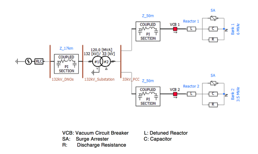
Fig. 1 shows the layout of the system being simulated and the following offers a brief overview:
• A Thevenin model is used to represent the background network and is based upon fault level and X/R ratio details;
• The site includes a 132/33 kV transformer connected to the grid via a 17 km, 132 kV underground cable. A PI section model is used to represent the cable;
• The standard/detuned capacitor banks are connected to the 33 kV point of common coupling (PCC) via 33 kV, 50 m underground cables. PI section models are used to represent the cables;
• Surge arresters are connected in parallel with the capacitors, one in each phase. VI characteristic are represented within the component parameters, based on the arrester datasheet.
Data used in system modelling is detailed below.
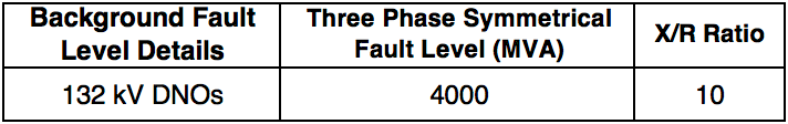
A. Background Network Data
The background network was modeled based on fault level data shown in Table 1 at the 132 kV DNOs busbar.

B. Transformer Data
The grid transformer was modeled based on the following:
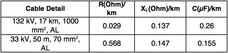
C. Cable Data
The 132 kV, 17 km incomer cable and 33 kV, 50 m cables for the banks were modeled based on:
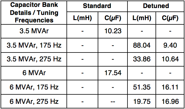
D. Standard/Detuned Capacitor Bank Data
The capacitor banks were modelled based on the following details. Rated voltage value of the capacitors in this study is 24 kV. Transient overvoltage limit is 2*sqrt (2) times the rated voltage (RMS value).
E. Surge Arrester Data
Silicone-housed DH Class, 10 kA, 22 kV MCOV type surge arresters were used in the simulations and the arresters’ VI curve was used in the PSCAD model. Maximum energy limit of the arrester used in this study is 62.7 kJ (2.85 kJ/kV MCOV).
Simulation Cases
To investigate the most severe case, occurrence in all three phases was considered, as was the worst possible opening point in terms of a restrike. For all simulation cases studied, results were obtained with and without surge arresters.
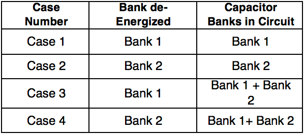
Standard Capacitor Bank Restrike Phenomena
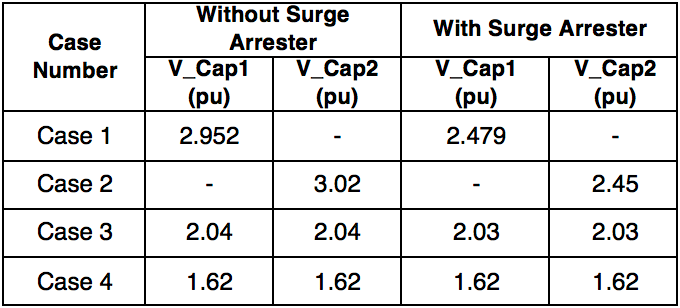
VCB Temporary Recovery Voltage (TRV) and voltage across the capacitors for single stage switching and back-to-back switching were investigated. Table 5 provides all cases investigated for a standard capacitor bank application.
Detuned Capacitor Bank Restrike Phenomena
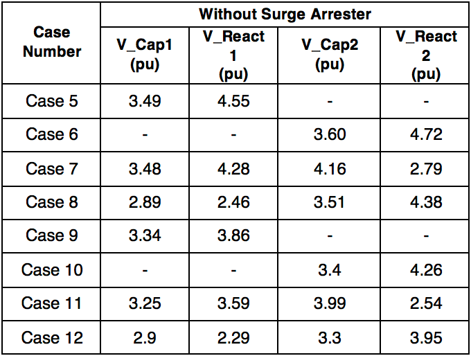
As with the standard capacitor bank investigation, TRV and capacitor voltage was investigated for various site configurations but for a de-tuned bank design across various de-tuning frequencies.
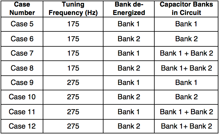
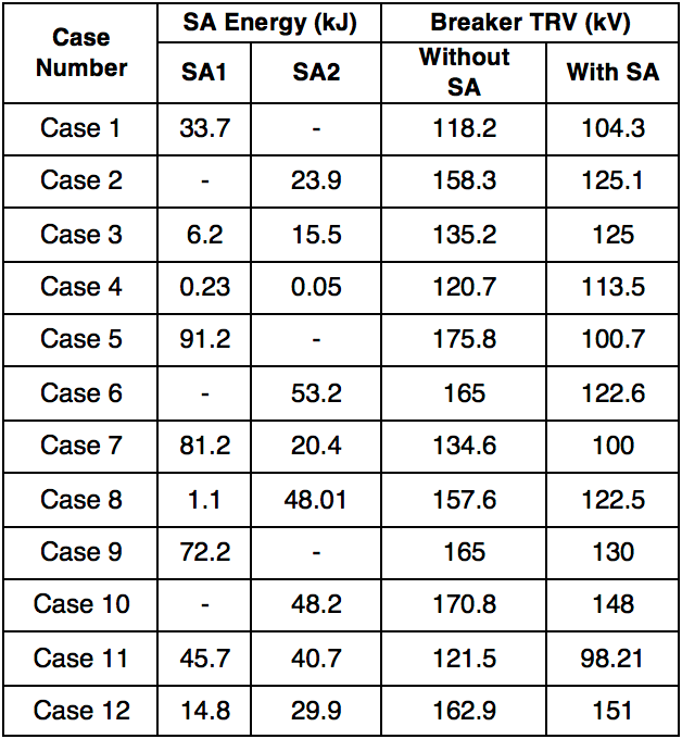
In summary, a total of 12 different cases were analysed. The energy absorption capability requirement of the surge arresters was also investigated for each case.

Results
The magnitude of the voltages was given as pu (per unit) – 1pu = 26.94kV (peak value of the line-to-ground voltage). Results were tabulated based on worst-case restrike switching points and assuming single restrike occurrence.
Overvoltages Across Capacitors, Standard Capacitor Bank
The worst-case voltage across the capacitor was found to be 3.02 pu in Case 2 – This is above permissible voltage levels. Voltage stress was reduced to 2.45 pu through inclusion of surge arresters, i.e. below the permissible level of 2.52 pu (67.88 kV/26.94 kV).
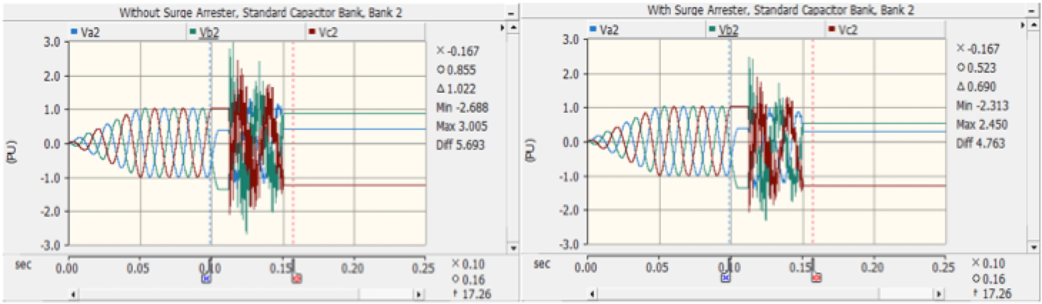
Based on with and without SA, Fig. 2 shows waveforms in three-phases for the worst-case overvoltage (Case 2).
Overvoltages Across Capacitors & Detuning Reactors, Detuned Capacitor Bank
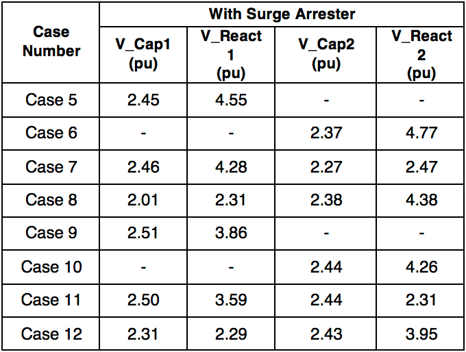
Worst-case voltage across the capacitors was found to be 4.16 pu in Case 7 and 3.99 pu in Case 11 for 175 Hz and 275 Hz detuned designs respectively. These values are above permissible voltage levels. Voltage stresses were reduced to 2.27 pu and 2.44 pu through inclusion of surge arresters, i.e. below the permissible level. Tables 7 and 8 tabulate overvoltages, without and with surge arresters.

Based on without and with surge arresters, capacitor voltage waveforms at C1 and C2 in three-phases are shown for Cases 7 and 11 in Figs. 3, 4, 5 and 6.
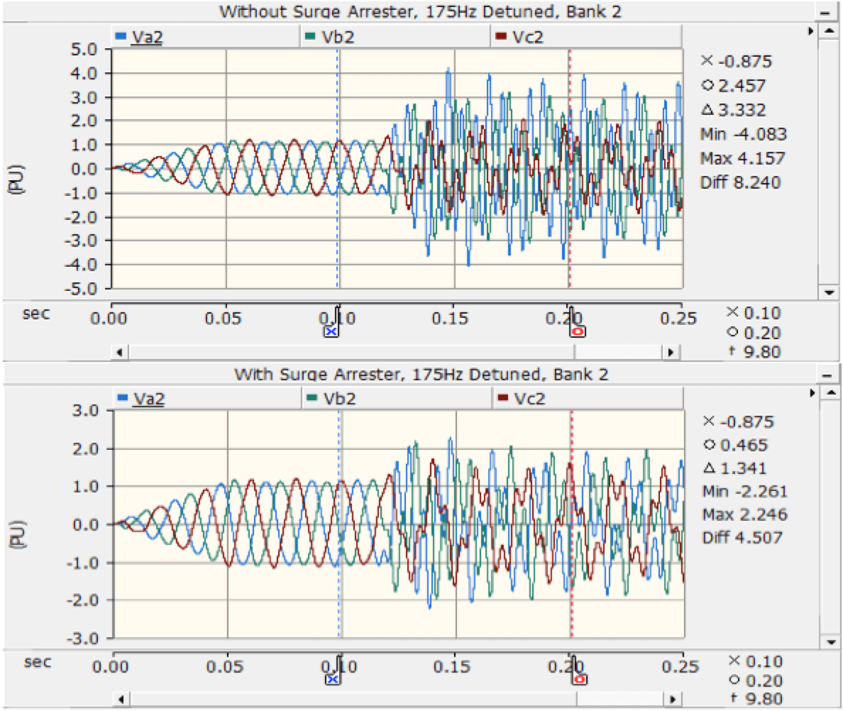
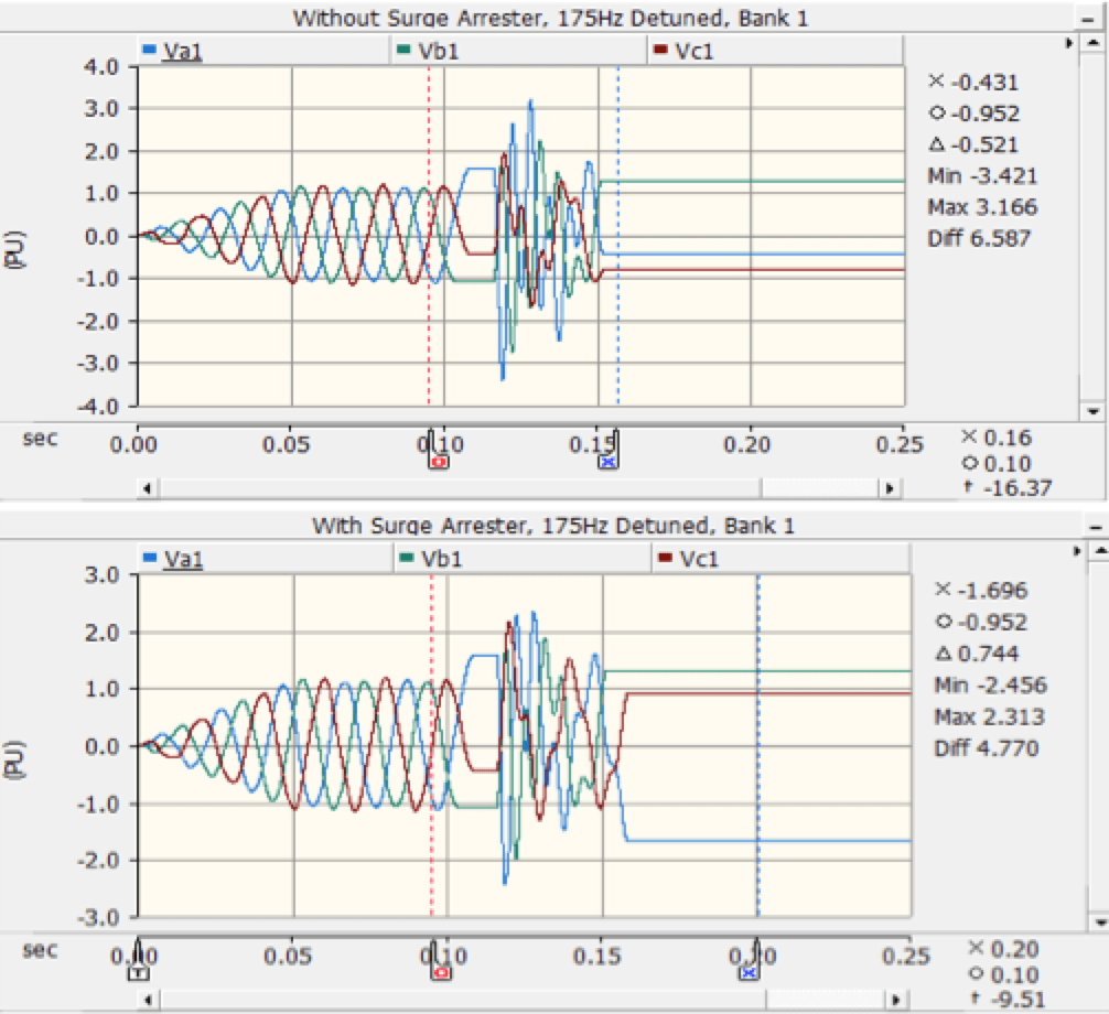
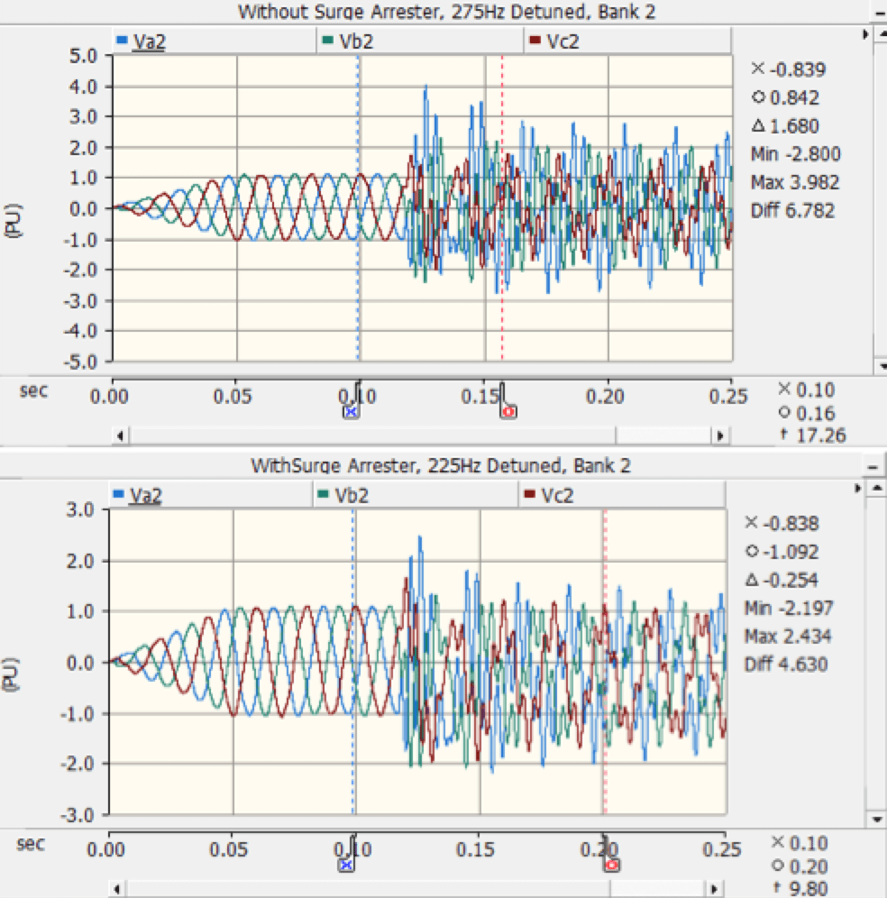
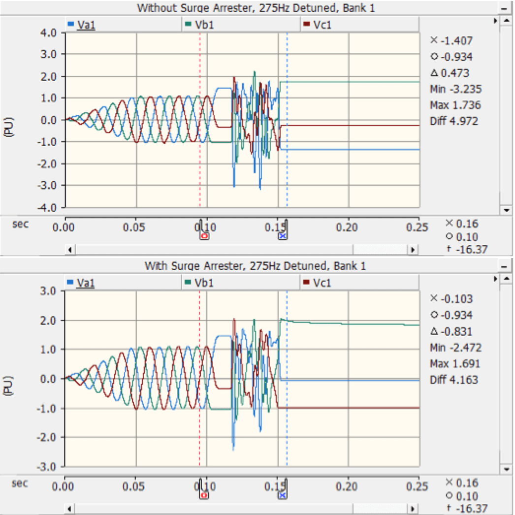
As can be seen from the above, connection of surge arresters across capacitors reduces capacitor overvoltages to less than design limits.
Absorbed Energy of Surge Arresters & Breaker TRV
Maximum energy absorption of the surge arresters and CB TRV were simulated for each case and are tabulated in Table 9. Tabulated surge arrester energy results are the highest energy levels across all phases. The worst-case absorbed surge arrester energy for each different design, standard, 175 Hz detuned and 275 Hz detuned, was found to be 33.7 kJ, 91.2 kJ and 72.2 kJ respectively.
In order to carry out breaker TRV simulations, cable capacitance values were not taken into consideration. TRV results were derived from almost 400 different switching cases (restrike time range is between 0.113 s – 0.120 s, breaker opening time range is between 0.113 s – 0.15 s.) and Table 9 gives highest voltages for each case, as without and with surge arresters. TRV capability of the CB is not considered here – only impact of a surge arrester on the CB’s TRV.

Conclusions
The following conclusions can be summarized from these results:
1. Overvoltages Across Capacitors
• Without surge arresters, probable restrike leads to switching voltage being exceeded on the capacitors for both standard and detuned capacitor bank designs. Such overvoltages could lead to capacitor breakdown;
• Compared to standard capacitor banks, detuned designs are exposed to higher voltage stress. Thus, using surge arresters in the detuned design is more essential than for a standard case;
• Increasing detuning frequency brings about higher voltage stress on capacitors in the detuned design.;
• Stage configuration has an impact on capacitor voltage stresses. In the detuned design, the highest voltage stresses occur for back-to-back restrike cases.
• For all cases studied, a DH class surge arrester, 22 kV MCOV, in phase to neutral connection is able to reduce the voltages to permissible levels for capacitors.
2. Surge Arrester Energy Requirements
• Compared to a standard capacitor bank, surge arresters in detuned designs absorb more energy;
• Increasing detuning frequency brings about less absorbed SA energy in the detuned design. However, it is still higher than the SA energy in a standard capacitor bank;
• SA energy level should not exceed rated energy withstand level;
• The worst-case SA energy level was simulated as 33.7 kJ for a standard capacitor bank and complies with SA rated energy level of 62.7 kJ;
• The worst-case SA energy levels for a detuned design were simulated as 91.2 kJ and 72.2 kJ. These do not comply with SA rated energy level of 62.7 kJ. Therefore, a SA with higher energy capability or using parallel SAs would be required. Using two SAs in parallel is a solution for a detuned bank design.
3. Impact of SA on CB TRV
• Even though SAs are not connected across the CB directly, results show that a SA helps reduce CB TRV since it mitigates voltage at the downstream side of the CB. As such, a SA connection reduces TRV indirectly;
• Based on cases simulated, a SA clearly reduces probability of restrike or multiple restrikes at CBs.

References
[1] A. Greenwood, Electrical transients in power systems, New York: Wiley India, 1991.
[2] S. Arigye-Mushabe and K. A. Folly, “Evaluation of switching capacitive currents by disconnect switches using DIgSILENT softwware tool,” 2014.
[3] IEEE Power Engineering Society, “IEEE Std 1531 IEEE guide for application and specification of harmonic filters,” The Institute of Electrical and Electronics Engineers, Ney York, 2003.
[4] IEEE Power & Energy Society, “IEEE Std C62.22 IEEE guide for the application of metal-oxide surge arresters for alternating-current system,” The Institute of Electrical and Electronics Engineers, New York, 2009. [5] B. S. Publication, “BS EN 60871-1,” UK, 2014.
[6] L. Gebhardt and R. Bernhard, “Surge Arrester Application of MV-Capacitor Banks to Mitigate Problems of Switching Restrikes,” in 19th International Conference on Electricity Distribution, Vienna, 2007.