Station post insulator development and innovation can contribute to substation design optimization by limiting the arcing distances necessary at busbars, disconnectors and other station apparatus. This is achieved by optimizing post insulator design by:
• selecting proper internal and housing material;
• reducing diameter;
• maximizing mechanical strength and stiffness;
• reducing number of stacks or intermediate flanges; and
• optimizing shed profile and creepage factor.
In addition, diagnostics contribute to long term service performance, facilitating predictive maintenance, reducing risk of flashover and unplanned outages, thereby maximizing both cost-effectiveness and operational efficiency.
This edited contribution to INMR by Marco Nosilati, Rodolfo Saraceni and Eros Stella of GE Grid Solutions, in co-operation with Alberto Pigini, discusses development and validation of a digital solution (referred to as ‘AIS Smart Disconnectors’), to enable comprehensive online assessment of condition.
This includes a post insulator diagnostic with leakage current sensor that allows predictive maintenance to leverage manufacturer expertise and device performance data. The end goal is to enhance longevity and reliability, even under demanding operating conditions.

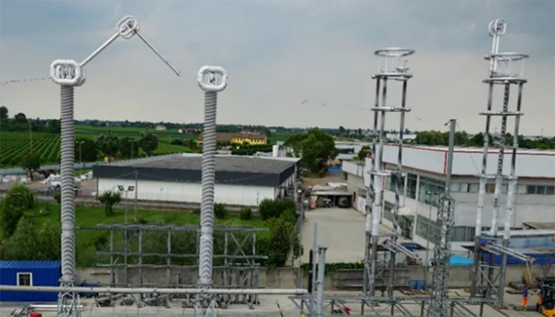
Most porcelain station posts today are still based on traditional and relatively inexpensive stacking technology, i.e. assembling insulators of different heights to reach desired arcing distance in the EHV-UHV range. This solution is the one with the greatest overall field experience, confirming its excellent performance, especially from the mechanical point of view.
At the same time, advanced porcelain solutions are now available, allowing production of single unit insulators of several meters (thus reducing the need for intermediate flanges) and with optimized profiles (i.e. by reducing shed thickness and tip radius).
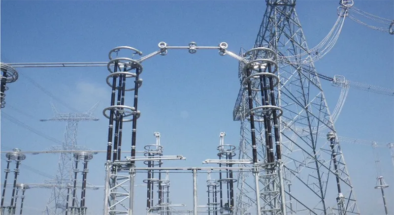
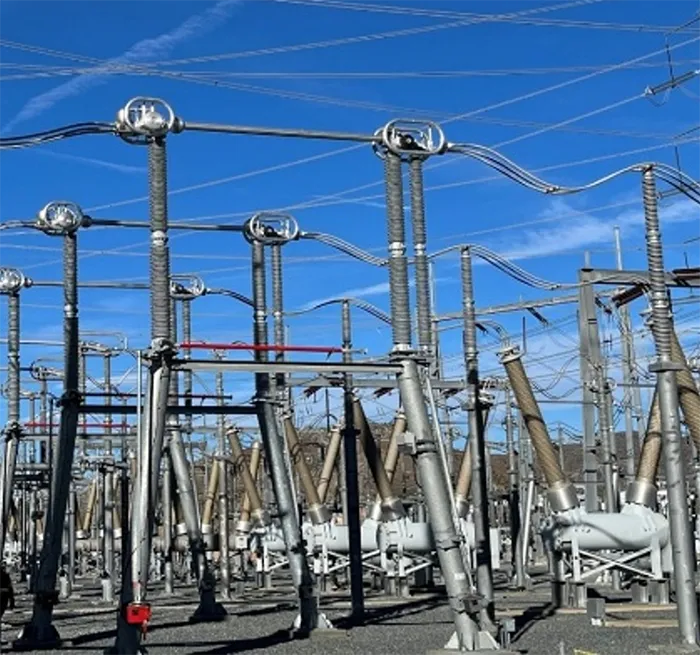
Due to their cost and technical maturity, porcelain post insulators remain a common solution applied up to the highest voltage levels, especially in AC (see Fig. 1).

A key issue, however, is that wide core dimensions are not easily feasible and require technical and manufacturing expertise. Manufacturing insulators with wide diameters could result in differential cooling after molding, leading to cracks. In addition, quality of the porcelain body and cement also need to be carefully considered.
A composite technology solution permits insulators of the necessary length without flanges and offers other advantages such as lower weight and good performance under pollution as well as earthquake. The main disadvantage is a higher cost compared to standard stacking of solid core porcelains. This limits such solutions to the lower range of HV and EHV applications.
Composite post insulators with hydrophobicity transfer material (HTM) housings are also an alternative solution for installations in DC. This is due to the different behaviour of pollution accumulation on DC insulators in harsh conditions, often in combination with stricter seismic requirements. Also, the cost become more competitive versus a porcelain stack solution.
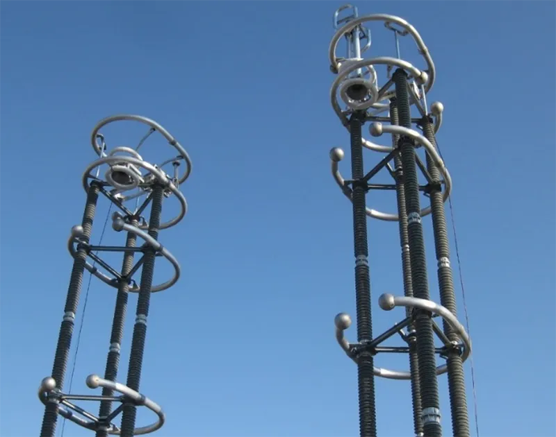
For UHV disconnectors, hollow core composite insulators filled with polyurethane foam or properly monitored eco-friendly gas are now the preferred solution due to the possibility increase diameter without a consequential increment in weight and cost-effectiveness. Still, these require proper design to comply with specific mechanical constraints (e.g. minimizing deflection at the top in the case of application on disconnectors) and must be tested from the sealing and monitoring points of view.

An intermediate solution is offered by porcelain insulators coated by RTV silicone having HTM characteristics, as shown in Fig. 4. This combines the advantages of porcelain and HTM materials.
The AIS Smart Disconnector is a new concept that starts with a well-studied design phase and appropriate sizing strategy from the electrical and mechanical points of view. Part of its development has been based on laboratory testing with the scope of confirming the layout before installation on site. The preliminary threshold of parameters used to integrate a monitoring system have also been redefined to provide cost-effective predictive maintenance planning by taking advantage of the manufacturer’s expert knowledge of disconnectors. The following will focus mainly on design, testing and diagnostics from an electrical perspective.
Design, Testing & Development of Diagnostic Criteria Toward Predictive Maintenance
Field performance begins at the design stage. Attention to specific details helps ensure proper functioning and reducing maintenance requirements throughout the service life of post insulators, whether of HTM or porcelain.
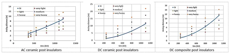
Design of post insulators for Air-Insulated Substations (AIS) is primarily guided by their performance requirements under continuous voltage, particularly in the presence of pollution, as well as their resilience to switching overvoltages. A preliminary assessment of required insulator sizing was conducted (see Fig. 5). As indicated, although switching overvoltages (simulated in laboratory conditions by switching impulses SI) determine design decisions in relatively clean environments, insulator performance under pollution becomes the critical factor at elevated pollution levels, especially for DC applications.
In particular, pollution performance becomes determinant in harsh environments – even taking into account the latest revision of the IEC standard for insulator selection under pollution that has added a new class “f – Extremely Heavy”.
AIS Smart Disconnectors are to be designed to maintain satisfactory performance under challenging pollution conditions, while also considering potential climate changes that may alter pollution severity during operation compared to initial design assumptions. In this regard, continuous real-time monitoring allows understanding if a permanent alert situation is caused by improper maintenance or by worsening pollution conditions over time.
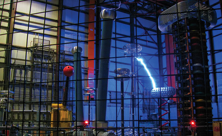
Pollution tests are systematically performed by GE Vernova under AC and DC voltages in many laboratories worldwide, as shown in Fig. 6. These tests help confirm the quality of the design and derive information for setting up suitable diagnostics criteria. Most are performed under the effective service configuration of the disconnector, i.e. by equipping the test objects with structure, live part, corona rings, etc. to make the test as representative as possible. This also allows studying and verifying how these components affect pollution deposition as well as the influence of two post insulators in parallel.
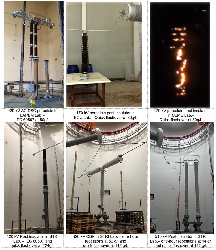

In addition to homologation tests according to IEC standards and customer technical specifications, tests were also performed using the quick flashover method (according to the latest revision of the relevant standard) to compare different insulator solutions and to derive information for setting-up the predictive maintenance system.
In particular, the tests performed allowed systematic measurements to assess the relationship between leakage current (maximum peak of current I, highest Ih), pollution severity and risk of flashover. Knowing this is necessary to refine the thresholds for a predictive maintenance algorithm for insulators. Maximum peak leakage current observed, together with its frequency of occurrence, are assumed the diagnostic indicator.
Based on detailed analysis of available experimental results, risk of flashover as a function of leakage current was defined in AC for ceramic insulators (see Fig. 7).
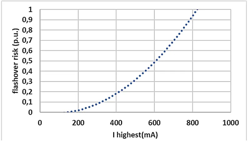
Data indicate that risk of flashover for ceramic insulators is low, with Ih lower than 250 mA but then increases reaching a value of 100% for leakage currents approaching 1A. Moreover, that diagnostic criterion should also consider repetition frequency of Ih: close to complete flashover, frequency of current peaks increases.
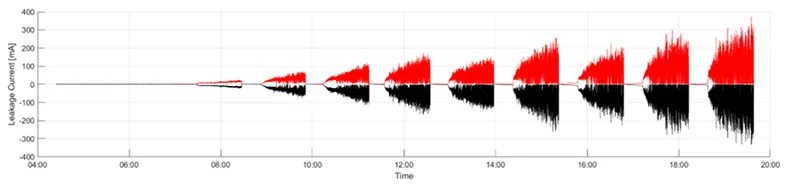
Similar criteria could be computed for HTM housing material solutions (e.g. composite or RTV). In this case, one must also consider loss of hydrophobicity over the time until the point where performance become close to porcelain as shown for example in Fig. 8 which records leakage current during the now standardized pollution test with salt fog.
While reaching hydrophobicity conditions close to that of non-HTM material, leakage current reaches values close to that observed for porcelain. In a series of 8 different polymeric insulators tested, no flashovers occurred, and all passed the severe tests with maximum leakage current reached in the withstand cases of up to about 400 mA.
In summary, similar withstand criteria to those for porcelain insulators could be applied to HTM insulators if looking only to the aspect of flashover. However, composite insulators pose challenges given that even low-level leakage currents can reduce performance by degrading hydrophobicity and damaging surfaces. Therefore, diagnostic criteria for HTM insulators will differ. Specifically, it is important to ensure leakage current stays below a few milliamperes to minimize ageing and intervention should be undertaken if an upward trend is observed.
Based on the above, the following alarm conditions have been proposed for porcelain insulators:
• SAFE CONDITION: Normal operation in service
• ATTENTION CONDITION: Probability of flashover is not negligible, some actions such as insulator washing can be scheduled.
• INTERVENTION CONDITION: Flashover is probable and suitable intervention (e.g. washing) must be taken promptly.
Table 1 gives preliminary indications for non-HTM ceramic insulators for AC applications, based mainly on expected risk of flashover as derived from laboratory results.
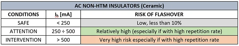

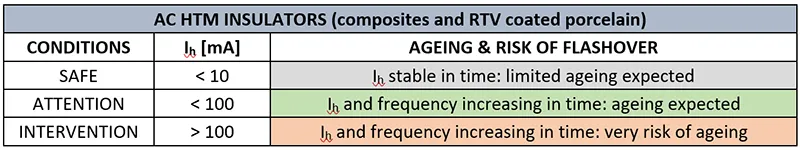
Table 2 gives preliminary indications for AC HTM insulators, taking into account possible impact of leakage current on insulator ageing. For HTM insulators reference is to be made to the Ih peak with high frequency. Considering that the presence of random peaks up to 250 A can be neglected both from the ageing and flashover point of view.
Thresholds for DC insulators are still under development. These should consider that, in the case of ceramic insulators, for the same withstand pollution severity, duration of the DC leakage current pulse is much longer than for AC while Ihighest is lower.
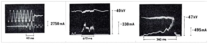
Statistical analysis of available data indicated that average duration of leakage current peaks for DC was about 0.6 seconds versus an average value for AC of about 5-10 cycles equal to 0.1-0.2 seconds. Maximum leakage current peak Ihighest in DC was found to be 3 to 5 times lower than in AC (2 to 2.5 times if reference is made to the rms value).
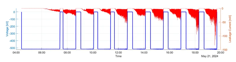
The same process of loss hydrophobicity over the test time is observed also in case of DC. The above is confirmed by data obtained on a composite insulator with an arcing distance equal to 6300 mm as shown in Figure 10 reporting the evolution of the leakage current during pollution tests in DC.

Smart Disconnector Monitoring & Diagnostics System
A diagnostic system was implemented to enable comprehensive online assessment of a disconnector’s condition, thereby facilitating predictive maintenance. Such predictive maintenance will reduce unplanned outages and routine interventions by ensuring maintenance is performed only when necessary, thereby also maximizing cost-effectiveness and operational efficiency. Leveraging manufacturer expertise and device performance data enhances longevity and reliability, even under demanding service conditions.
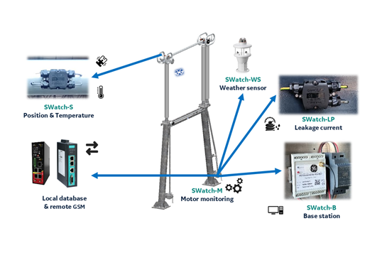
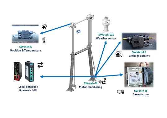
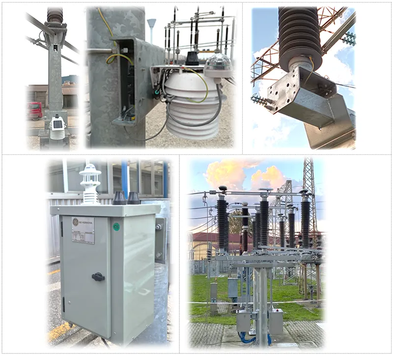
Fig. 11 shows the AIS Disconnector full kit typical installation. This product enables condition-based maintenance via alerts collecting in real-time data about leakage current above insulators, live part position and temperature, while also tracking motor activity such as current, voltage, and movement count. Data is delivered to utilities through a web interface using GMS for status and operational monitoring. In addition, it could be integrated in the substation SCADA system via the most common protocol (Modbus, IEC 61850 or DNP3).
Each disconnector is equipped with a position and temperature sensor per live part, which communicate with the central cabinet via bluetooth and have energy harvesting by a solar panel. A leakage current sensor on one post insulator, and a motor sensor depending on the mechanism system (three pole or single pole master/slave operated). Furthermore, a single weather station is used to monitor the weather phenomena for entire substation to corelate with the leakage current behaviour. Remote monitoring is supported via GSM using multiple protocols and an online dashboard. Predictive maintenance algorithms, based on product tests, provide accurate alarms and reduce unnecessary interventions.
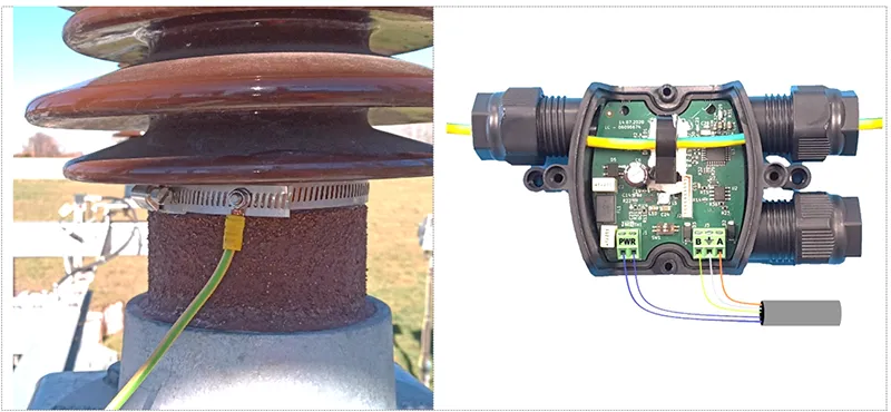
Leakage currents that flow along the surface of insulators are collected in the field by a sensor through an adaptive metallic collar, shown in Fig. 12, that is monitored within a time-configurable window. The current peak (Ih) is recorded with high-speed sampling, saving only the highest value and frequency repetition and its timestamp within each time window to minimize data traffic. RMS values are also acquired to provide an overview over time.
Simultaneously, the data is continuously being checked by a dedicated algorithm to detect situations that might require utility attention. If thresholds are exceeded, the system issues alarms either locally or remotely. The time interval between the alert and the onset of a hazardous condition is generally sufficient for personnel to plan and carry out necessary interventions on site, including maintenance such as insulator cleaning.
Cybersecurity is another key aspect. Although these products only monitor and cannot control disconnectors, due to the sensitive data being collected they must comply with IEC 62443. Hardware must satisfy product requirements with secure boot, memory encryption, and physical segregation, as per IEC 62443-2. All external communications are secured through certification, role-based access and permission management to maintain data integrity and authenticity.
The performance and robustness of the monitoring system has been verified at different laboratories, while making pollution tests on ceramic as well as composite insulators. For example, tests were made at EGU HV Laboratory in Prague, STRI in Ludvika and CEME Laboratory. These compared measurements of the current derived by the collar with that measured according to standard laboratory methodology, i.e. deriving current from the isolated base of the test object.
To assess robustness of the system, the performance of the measuring system under short circuit or heavy transients was verified during salt fog tests with the rapid procedure. These included numerous flashovers, confirming the robustness of the solution.
Similarly, the position and temperature sensors were compared with a reference measurement system and all wireless communication Bluetooth and GSM were tested to avoid any interference from strong electric and magnetic fields at 50 and 60 Hz, as present in substations.
Finally, to verify reliability in the field, the system was pilot-tested in various substations by various DSOs and TSOs and has already been in operation for several years. Photos of some of these installations are shown in Fig. 13.
Moreover, to meet the needs of a major U.S. TSO, several fully equipped 550 kV three-pole vertical break AIS Smart Disconnectors will be delivered to a Mojave Desert substation by end of 2025. Real-time monitoring and predictive maintenance will support effective remote management and reliable operation in this harsh environment.
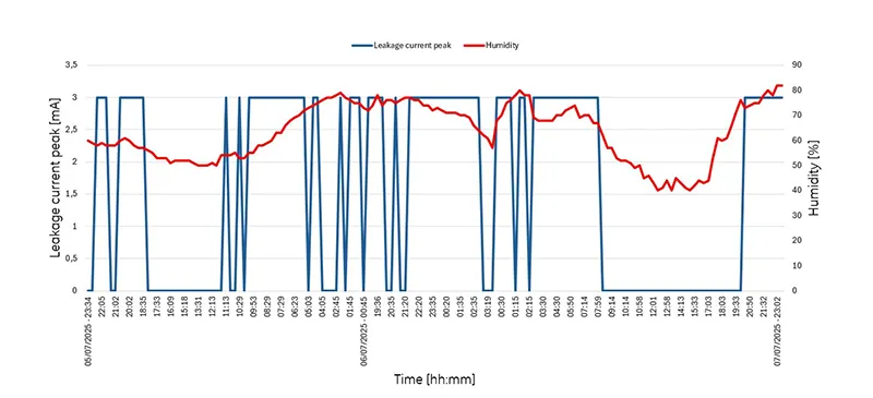
Field experience has confirmed the effect of weather on leakage current. In the presence of humidity in the pollution layer, there is an increase in leakage current, but this is followed by a decrease after rain due to insulator washing.
Fig. 15 illustrates an example of the influence of humidity. Increased humidity in the morning and at sunset causes a noticeable spike in leakage current. Leakage current in the case under examination is low because the pollution level is less than that used for design of the post insulator being monitored.
Other installations are now also underway with major TSOs in Italy, India, Germany and Argentina. The aim has been to help these utilities with cost-effective predictive maintenance. At the same time, field data is being collected in different parts of the world to compare against laboratory data. This will help further refine the algorithm, as already applied in the AIS Smart Disconnector.
Conclusions & Future Work
• Development of disconnectors to assure high service reliability requires a well-structured design and an appropriate sizing strategy from the electrical and mechanical points of view. This starts with focus on technical details during the design phase, followed by verification through laboratory testing.
• Post insulators in AIS Smart Disconnectors are continuously monitored based on leakage current peaks which are deemed the most representative feature of the health of insulation. A tailored algorithm was developed that takes different materials and configurations into account.
• The AIS Smart Disconnector integrates in the DSC a monitoring and diagnostic system that assesses the entire condition of disconnectors and post insulators from the mechanical and electrical points of view. This provides a powerful and cost-effective predictive maintenance service to the utility. System performance has been widely verified in the laboratory and is now installed at many substations.
• Many studies and tests were performed during development of the AIS Smart Disconnector to study and verify all electrical and mechanical features. Interesting results were found related to polymeric materials as an alternative to multiple long stack porcelain post insulators under heavy pollution (also considering possible loss hydrophobicity and correlation with humidity conditions over the day).
• As far as disconnector diagnostics, available data has allowed setting up thresholds to assess condition of AC disconnectors from the pollution point of view. Only preliminary data are available for DC and additional laboratory investigations will therefore be required. Mechanical and thermal parameters have been defined by the applicable type test. Extensive field installations will help validate and refine tailored thresholds for the condition monitoring algorithm.
Bibliography
[1] A. Pigini, M. Nosilati, E. Stella and R. Saraceni, “Pollution design and on-site monitoring of insulators for AIS disconnectors equipped with porcelain insulators under AC voltage,” INMR World Congress, 2022.
[2] E.Stella, M.Nosilati, F.Chacon and A.Pigini, “Sizing and testing of HVDC disconnectors from the dielectric point of view,” in Cigre general session Paper A3 10773, 2022.
[3] R. Saraceni, M. Nosilati, D. Momesso and E. Zozzolotto, “Experiences in dimensioning and condition monitoring of HTM PU-filled insulators for HVDC disconnector application,” Gridcon 2025 – New Dheli (India), 2025.
[4] A.Pigini, M.Nosilati and D.Momesso, “Optimized Selection of Post Insulators for Disconnectors & Other Substation Applications,” in INMR World Congress, Tucson, 2019.
[5] R. Saraceni, A. Pigini, M. Nosilati and E. Stella, “Real-time pollution monitoring and diagnostics of Air Insulated Switchgear oriented to predictive maintenance,” Cigrè Paris Session, 2024.
[6] IEC/TS 60815-1, “Selection and dimensioning of high-voltage insulators intended for use in polluted conditions – Part 1: Definitions, information and general principles”.
[7] A.Pigini, M.Nosilati, F.Rosin and D.Momesso, “AIS disconnector design from the pollution point of view,” in IEEE RVP-AI/2019, Acapulco Mexico.
[8] IEC/TS 63414, “Artificial pollution tests on high-voltage polymeric insulators to be used on a.c. and d.c. systems”.
[9] IEC 60507:2013, “Artificial pollution tests on high-voltage ceramic and glass insulators to be used on a.c. systems,” 2013.
[10] IEC/TS 61245, “Artificial pollution tests on high-voltage ceramic and glass insulators to be used on d.c. systems,” 2015.
[11] A. Pigini, M. Nosilati, E. Stella and R. Saraceni, “Pollution tests results on live tank circuit breakers with polymeric housing,” INMR – World Congress, 2023.
[12] R.Cortina, G.Marrone, A.Pigini, L.Thione, W.Petrusch and M.P.Verma, “Study of the dielectric strenght of external insulation of HVDC systems and application to design and testing,” in CIGRE General Session, 1984.
[13] IEC 61850, “Communication networks and systems for power utility automation”.