Different types of insulators are available for application on overhead transmission lines, including glass or porcelain string insulators, porcelain long-rods and composite/polymeric insulators. Within each category there are also a range of designs, materials, qualities and prices. At the same time, there are also several alternatives available to improve performance of insulators intended for polluted service areas, from advantageous shed profiles to coating with RTV silicone material.
Given these many options, there are a host of questions when deciding on which insulators to select for any new project, such as: What is the best design for that environment? What is the best material and what criteria must be taken in account when selecting it? Which parameters are most suitable for in service evaluation of condition? What will be the estimated service life? and so on.
Unfortunately, there is no simple answer to all these questions. But it is possible to note the different elements to be considered when evaluating and comparing all possible solutions.
This edited past contribution to INMR by Javier García at La Granja Insulators in Spain, reviewed important considerations when selecting the most suitable type of insulator for application on an overhead transmission line.

Mechanical Considerations
An insulator acts mainly as a mechanical support. As such, only after all mechanical aspects of any design have been finalized are the required electrical characteristics added. In fact, mechanical characteristics are so important to the function of an insulator that they are the only commonality found in all markings on insulators. Another issue to consider is consequence of mechanical failure, e.g. is it only loss of leakage distance or is it a dropped conductor. This of course depends on design of the insulator. IEC 60797 establishes the mechanical residual test methods and acceptance criteria for glass and porcelain string insulators under dielectric breakage.
The user must also determine maximum loading that the line will ever apply to the insulators, including weight of conductor and hardware, ice and wind loading and any other load factors. Suspension insulators are rated in terms of their Specified Mechanical Load (SML). Manufacturers usually recommend that the insulator never be loaded to more than 50% of its SML, which is a guaranteed minimum ultimate strength rating. Each batch of insulators produced is sampled for mechanical strength and all samples must meet or exceed stated SML value based on statistical criteria. The routine test load is the proof load applied to each unit and also the maximum load that the insulator should ever experience in service. IEC 60383-1 and IEC 61109 respectively establish mechanical test methods and acceptance criteria for porcelain insulators, glass insulators and composite insulators.
Electrical Considerations
The electrical characteristics of an insulator are imparted to it by the surrounding air. This is defined principally by its arcing distance, namely “the shortest distance in the air external to the insulator between the metallic parts which normally have the operating voltage between them”. Impulse withstand/flashover and dry power frequency characteristics are all based on dry arcing distance. Some might argue that the wet power frequency withstand/flashover characteristics are determined by leakage distance but that argument only holds within a narrow band. Leakage distance plays a role but as a contributing factor. IEC 60071-1 recommends the withstand voltage associated with the highest equipment voltage.

Selecting & Dimensioning HV Insulators for Polluted Service Areas
The past edition of the IEC TS 60815 series developed new techniques for selecting and dimensioning high voltage insulators and established a process to determine the most efficient insulation. This technical specification recommends three approaches to select suitable insulators based on system requirements and environmental conditions:
• Approach 1: Use past experience
• Approach 2: Measure and test
• Approach 3: Measure and design
The applicability of each approach depends on available data, time and the economics of a project. Some of the parameters required for these approaches include:
1. Determining Reference Unified Specific Creepage Distance (RUSCD)
Fig. 1 shows the relationship between site pollution severity (SPS) class and reference unified specific creepage distance (RUSCD) for insulators. The bars are preferred values representative of a minimum requirement for each class and are given for use with Approach 3 (i.e. measure and design) of IEC/TS 60815-1. If site pollution severities are available, an RUSCD is recommended that corresponds to the position of the SPS measurements within the class, following the curve.
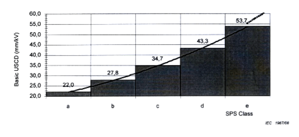
Basic USCD (mm/kV*)
* r.m.s. value of highest operating voltage across insulator.
Site pollution severity (SPS) classes:
a: Very light
b: Light
c: Medium
d: Heavy
e: Very heavy
For Type A pollution (i.e. inland, desert or industrial areas), SPS is calculated from ESDD and NSDD values. For Type B pollution (i.e. coastal areas where salt water or conductive fog is deposited onto insulator surfaces), SPS is calculated from SES (site equivalent salinity).
2. Choice of Profile: Glass & Porcelain Insulators
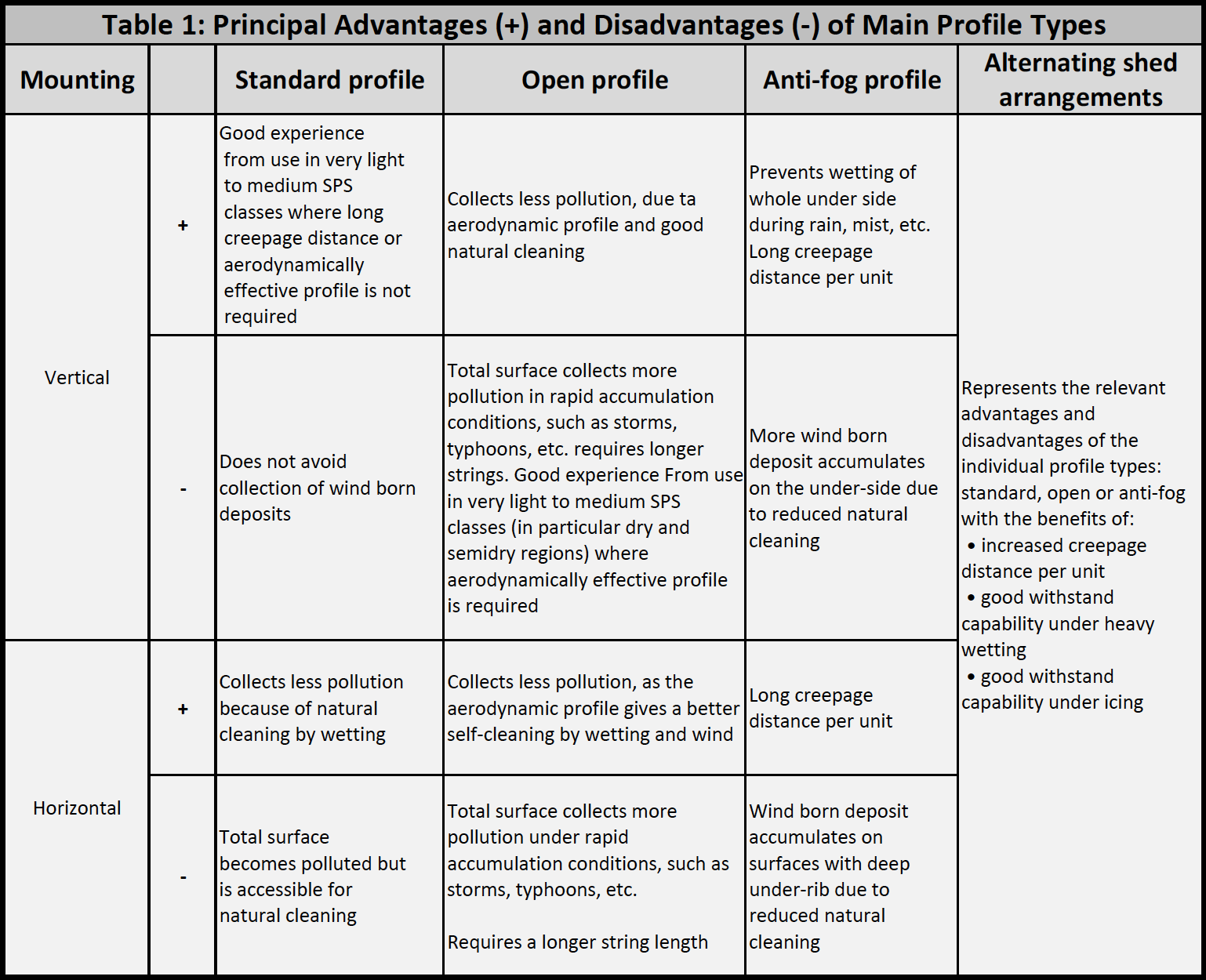
Different types of insulators and even different positions on the same insulator type accumulate pollution at different rates in the same environment. In addition, variations in the nature of pollutants may make some shapes of insulator more effective than others. Table 1 from IEC TS 60815-2 briefly summarizes the principal advantages and disadvantages of the main profiles with respect to pollution performance.
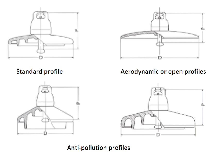

3. Profile Suitability: Glass & Porcelain Insulators
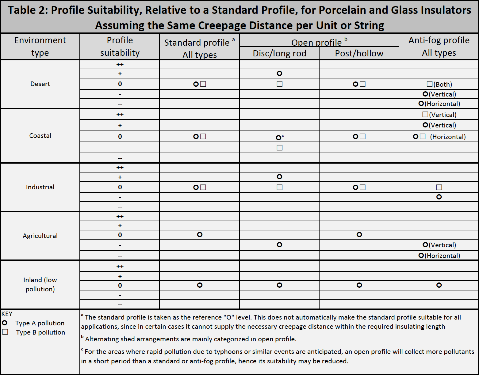
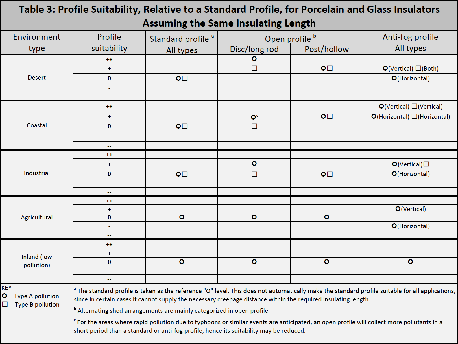
Tables 2 & 3 in IEC TS 60815-2 give simple merit values for porcelain and glass insulator profiles. Table 2 gives profile suitability, relative to standard profile assuming the same creepage distance per unit or string. Table 3 assumes the same insulation length. Both review the principal advantages and disadvantages of the main profile types with respect to pollution performance.
Moreover, IEC TS 60815-2 also gives profile parameters to take into account, e.g.:
• Alternating sheds and shed overhang;
• Spacing versus shed overhang;
• Minimum distance between sheds;
• Creepage distance versus clearances;
• Shed angle;
• Creepage factor.
4. Polymeric Insulator Profiles & Parameters
Chapters 8 & 9 of IEC TS 60815-3 give recommendations for polymeric/composite insulators profiles and parameters to take into account, including:
• Alternating sheds and shed overhang;
• Spacing versus shed overhang;
• Minimum distance between sheds;
• Creepage distance versus clearances;
• Shed angle;
• Creepage factor.

5. Pollution Test Standards
Pollution tests on glass and porcelain insulators in a laboratory can be carried out with two main objectives:
• To obtain information about the pollution performance of insulators (i.e. comparing different insulator types/profiles);
• To verify performance in a configuration as close as possible to that in-service.
IEC 60507 prescribes the procedures for artificial pollution tests applicable to porcelain and glass insulators for overhead lines. Two categories of pollution test methods are recommended for these standard tests:
• Salt fog method in which the insulators are subjected to a defined ambient pollution;
• Solid layer method in which a fairly uniform layer of a defined solid pollution is deposited onto the insulator surface.
These standardized laboratory pollution test methods are not applicable for composite (polymeric) or RTV coated insulators, although a proposed test method for artificially polluted composite insulators is covered in CIGRE TB 555: “Artificial Pollution Test for Polymer Insulators”. In the case of naturally polluted insulators removed from service, a recent CIGRE TB 691 (WG D1.44), “Pollution Test of Naturally and Artificially Contaminated Insulators” summarized recent experience with the so-called rapid flashover test methods:
• Rapid flashover Test (RFO, based on IEC 60507 solid layer test);
• Quick flashover (QF, based on IEC 60507 salt fog test).
Both tests can be applied for glass and porcelain as well as for composite insulators for AC and DC applications. The objective of these tests is based on the need for a reliable diagnostic of naturally polluted insulators so as to evaluate residual dielectric strength. Also considered is the trend to make testing more cost-effective and time-efficient, even for artificially polluted insulators.
Any reduction in performance can be due to pollution in the case of ceramic insulators or due to a combination of pollution and ageing in the case of polymeric insulators. In both cases, however, residual pollution strength should be quantified in terms of flashover voltage and not withstand voltage. This is because withstand voltage does not provide the user with information about the probability of flashover or the standard deviation in flashover voltage.
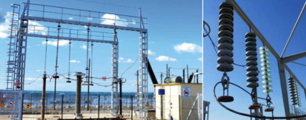
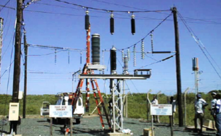
6. Insulator Test Stations
Sometimes, the combination of all the varying environmental parameters that influence insulator behaviour over its lifetime are difficult to simulate and accelerate. The validity of laboratory testing is thus often questioned since the procedures adopted for these tests may not take into account significant factors that would be encountered in service; or they may overemphasize others.
Given this, evaluation of insulator performance at naturally polluted outdoor test stations is becoming more important. Although involving longer test durations and still requiring care in correct interpretation of test data, results tend to be accepted with more confidence. An outdoor test station is also a valuable tool for new insulation technologies for which there is still no technical or normative specification for testing or characterization.
CIGRE Technical Brochure No. 333, 2007 “Guide for the establishment of naturally polluted insulator testing stations” serves as a general guide for establishing natural test stations that will facilitate comparison of various insulator designs, exploration of particular aspects of insulator performance and/or selection of the most appropriate insulation for a particular application. While such testing relates specifically to insulators intended for use under AC conditions, certain aspects are applicable to DC as well. Typical goals for such testing could be one or more of the following:
• To compare performance of insulators of different design;
• To compare performance of insulators from different manufacturers;
• To dimension insulators for a particular environment or application;
• To examine behaviour of insulators of different dielectric materials;
• To compare performance of insulators in different orientations;
• To explore effects of specific parameters such as profile geometries or insulators diameters;
• To identify possible weaknesses or failure mechanisms of an insulator design;
• To estimate life expectancy of various insulators;
• To serve as a qualification test for potential suppliers;
• To establish effectiveness and service life of special insulator treatments such as washing, greasing, silicone rubber coating, shed extenders, etc.;
• To assess performance of other outdoor equipment insulation such as transformer bushings, surge arresters, cable terminations, etc.
The severity of pollution and prevailing climate of an outdoor test station should ideally be representative of conditions found on the system. As is the case for laboratory tests, over-acceleration of ambient stresses can yield misleading results. Contamination severity assessment by means of ESDD and NSDD measurements and/or directional dust deposit gauges should be undertaken to ensure that the appropriate site has been selected.
Insulator test stations have a range of sizes and levels of sophistication and can be categorized as:
• Research stations;
• Simplified, on-line stations;
• In service test structures;
• Mobile insulator test stations.

Leakage current activity (including number of flashovers experienced), climatic effects and pollution severity are all usually monitored at these sites. In addition, performance of test samples should be judged based on regular inspection of insulators, including close-up visual examination of surfaces, assessment of the hydrophobicity of the dielectric material and evidence of electrical activity.
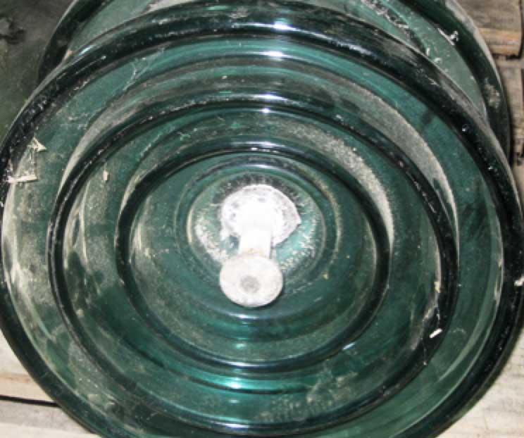
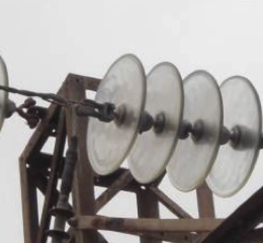
Corrosion on Insulators
Insulator Fitting Corrosion Mechanism
Insulator corrosion generally occurs whenever an insulator is polluted and there is presence of humidity. Leakage currents start when the surface is covered by a deposit of wet pollution, with amplitude a function of degree of pollution (i.e. amount of soluble salts). Polluted and wet insulators energized with AC voltage display a biased leakage current having a DC component that causes electrolytic corrosion of pins. Impact of leakage current is most harmful when frequency and duration of wetting periods are high, such as in tropical climates, and also when pollution finds a hygroscopic surface. Hence the special importance of monitoring for inert contaminants that absorb or retain humidity.
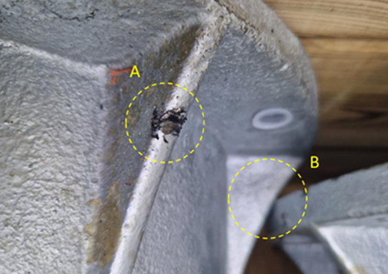
Such corrosion is more important for DC than for AC voltages given the same site due to unidirectional current and electrostatic phenomena that contribute to pollution deposition. For insulators, dominant electrolytic effects only add to atmospheric initiated corrosion, particularly those due to formation of oxidizing agents caused by presence of arcs near fittings. These can be initiated and maintained during periods of humidification and drying that precede and follow critical conditions or whenever the insulator is more humid. Protective field dispatch accessories can be beneficial to limit such humidification and drying periods, which accelerate insulator fitting corrosion in those units that are most electrically stressed. Corrosion can result in:
1. attack on galvanization;
2. attack on internal steel structure with formation of a conductive rust deposit that can flow onto the dielectric
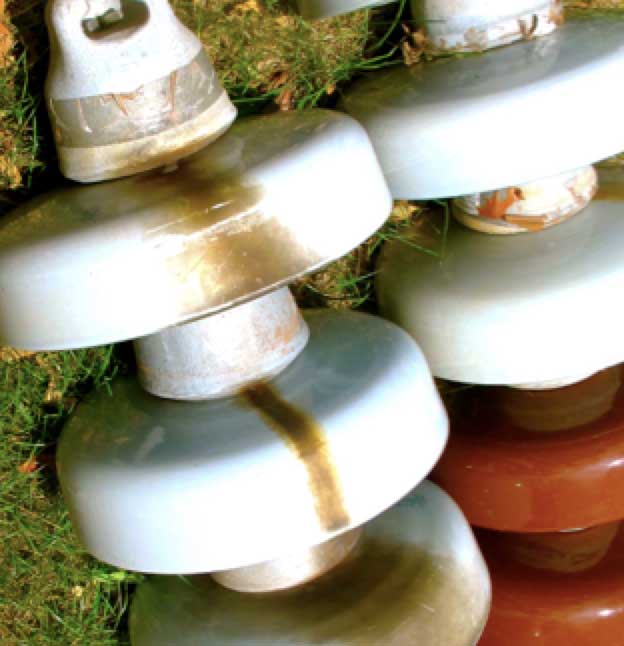
The most severe cases of corrosion can be found in tropical areas with heavy marine pollution and in areas where pollution by dust accumulation occurs over long periods without rain in combination with high environmental humidity.

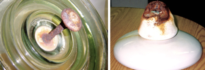
Phenomena Linked to Corrosion of Metal Parts
Corrosion of insulator fittings can have the following effects:
1. Impact on mechanical resistance
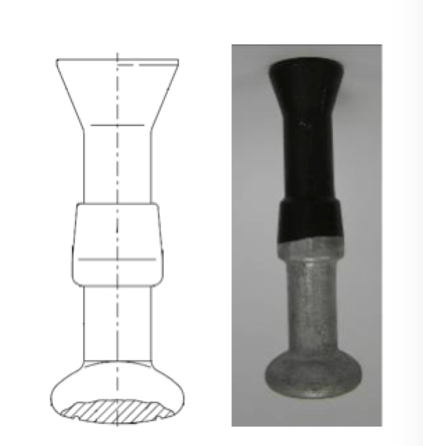
This applies particularly to the pin of the insulator when the section of the corroded part becomes reduced, such as reduction in pin diameter;
2. Impact on electrical resistance due to formation of rust deposit on surface
This deposit can also cause damage to the insulation due to concentrated electric field around this new electrode.
3. Breakage of dielectric due to expansion of corroded pin
Remedies to improve resistance to corrosion on insulators typically involve special metal protection developed to avoid or delay this phenomenon.
These remedies consist of reinforced galvanized fittings and use of sacrificial zinc sleeve protection.
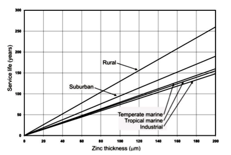
• Reinforced galvanized fittings
Ch. 26 of IEC-60383-1 standardizes minimum average coating mass for the metal fitting of insulators: 600 g/m2 (85 µm) but this value can increase to 140 µm for insulators installed in high corrosion areas in order to prolong service life.
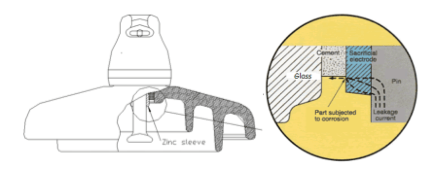
• Zinc sleeve is galvanically positive and has a large potential difference from iron
This works as a sacrificial electrode at the cement boundary where current flows. The zinc sleeve is free from accumulation of corrosive products.
IEC-61365 specifies minimum requirements for a zinc sleeve but this can also be improved to increase corrosion performance.
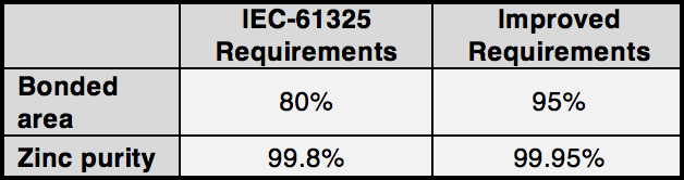
Also, IEC-61365 specifies a test method for control of the zinc sleeve. Future work in standards and norms would have to include zinc sleeve requirements and tests methods within IEC-60383-1 (for AC lines).

Operating Parameters
Among the principal objectives of any overhead line maintenance policy is to maintain the number of fault outages at acceptable levels. In this regard, a database containing key information on line insulation is an efficient tool to track and evaluate performance. The information this database should contain includes:
• Type/sub-type of strings;
• Type of insulation: glass, ceramic, composite, coated glass, etc.
• Sub-type of insulator: standard profile, pollution profile, etc.
• Number of insulators per string;
• Manufacturer of the insulation;
• Insulator traceability data (production order, date, etc.)
• Standards;
• Year of installation;
• Manufacturer/applicator of silicone material;
• Estimated end of life;
• Degradation environment: Normal, hard or very hard.
Several maintenance indicators are normally used by utilities:
• Number of faults;
• Insulator breakage rate;
• Washing frequency.
Also a range of maintenance methods and procedures are known:
• Aerial inspection;
• Ground patrol inspection;
• HD recording;
• Infrared inspection.
Trends in maintenance indicators together with findings from inspections can then link with the database to help decision-making with respect to maintenance or replacement of insulation. There is also the opportunity for evaluation and comparison of different types of materials, insulator profiles and manufacturer qualities.
Estimated End of Life: Glass & Porcelain Insulators
Insulators are expected to perform with high reliability over long periods of time. Various design parameters, as discussed above, choice of material as well as mastering the manufacturing process are all required to maintain reliability over the long-term.
An insulator comes to the end of its working life when it fails mechanically, flashes over with unacceptably high frequency or gives evidence of deterioration to a condition likely to lower its safety factor in service. All insulators are affected to some extent by impact, cycling (both thermal and mechanical), weathering, conductor motion, corrosion and cement growth. Determining when is the time to replace insulators is key to optimizing maintenance costs and there are several potential modes of degradation. Some are easily detectable by visual inspection while others, such as porcelain and composite insulators, may require more sophisticated methods. Degradation modes can also be due to easily detectable mechanisms such as slip of metal fittings, pin corrosion or surface erosion – all considered to be valid reasons for insulator replacement.
CIGRE has established a test procedure to determine the state of cap & pin as well as long-rod insulators and to decide on time for replacement: “Guide for the assessment of old cap and pin and long-rod transmission line insulators made of porcelain or glass: What to check and when to replace”. CIGRE Technical Brochure No. 306, 2006 established a testing sequence with a number of non-destructive tests including visual tests (e.g. degree of corrosion) as well as dimensional, thermal and combined thermo-mechanical tests. This first series of tests is followed by destructive mechanical testing. A probability diagram based on a normal distribution is used to analyze failing load test results. With probability (risk) of failure on the ordinate and failing load on the abscissa, failing load characteristics are represented as straight lines. That way, changes in strength are easily seen. To help users, the document includes a number of typical cases of analysis of test result called “Reference Scenarios” that are useful to assess the condition of the insulator.
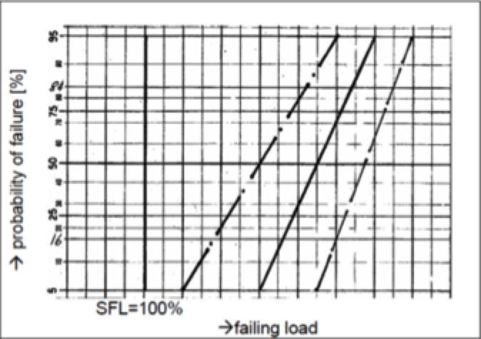
Failing load characteristics are represented by:
• dashed line for an insulator sample tested when new;
• solid line for insulators as received from a line;
• dashed/dotted line for insulators that have been submitted to thermo-mechanical testing (TMP test).
The SFL (specified failing load) is marked with a solid vertical line. For the example of ”Reference scenario F1”, the reductions in strength in this diagram are not representative of high quality products. Ageing and TMP tests should have only negligible impact on products of high quality.
Estimated End of Life: Composite Insulators
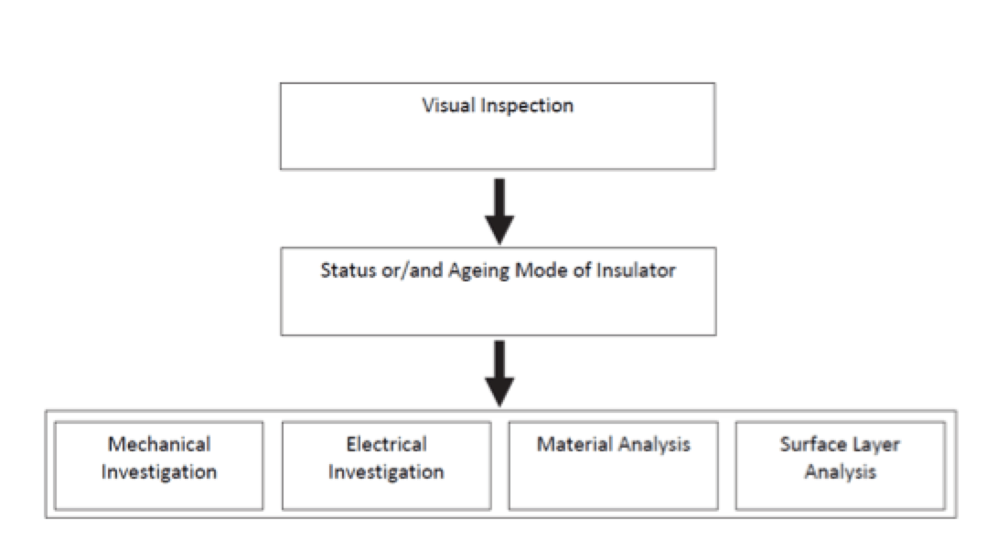
Parallel to this document, another Technical Brochure published by CIGRE assists evaluation of the technical condition of aged, old or failed composite insulators: “Guide for the assessment of composite Insulators in the laboratory after their removal from service” (CIGRE Technical Brochure No. 481). Different methods, philosophies and tools are described which enable some conclusion regarding the residual lifetime of composite insulators of the same age and design family. The document also gives indications for research and evaluation in the case of investigating a failure or a unit considered at high risk of failing. This is based on a recommended sequence of testing on samples removed from different stress zones on the line.
Conclusions
Selection of insulator type is not a simple task, especially if the insulator will be installed in a highly polluted area. Numerous documents (e.g. IEC standards, CIGRE Technical Brochures, etc.) are available to help select the most appropriate insulator, to monitor its behaviour in service and to determine when it is nearing end-of-life.
Different solutions are available to improve insulator performance in high corrosion areas.
Several factors must be considered when it comes to optimizing selection of insulator type:
• More effective designs/materials;
• Maintenance costs: Inspection cost, cleaning cost, replacement cost, etc.;
• Breakage rate in service, to be guaranteed by the supplier;
• Severity of consequences in case of failure (mechanical breakage or electrical failure;
• Expected end-of-life.
References
[1] IEC 60050-471: International Electrotechnical Vocabulary. Part 471: Insulators
[2] IEC 60071-1: Insulation co-ordination – Part 1: Definitions, principles and rules
[3] IEC 60575: Artificial pollution tests on high-voltage ceramic glass insulators to be used on a.c. systems.
[4] IEC 60797: Residual strength of string insulator units of glass or ceramic material for overhead lines after mechanical damage of the dielectric.
[5] IEC-60383-1: Insulators for overhead lines with a nominal voltage above 1 000V: Ceramic or glass insulators units for a.c. systems – Definitions, test methods and acceptance criteria
[6] IEC/TS 60815-1: Selection and dimensioning of high-voltage insulators intended for use in polluted condition – Part 1: Definitions, information and general principles
[7] IEC/TS 60815-2: Selection and dimensioning of high-voltage insulators indented for use in polluted condition – Part 2: Ceramic and glass insulators for a.c. systems
[8] IEC/TS 60815-3: Selection and dimensioning of high-voltage insulators indented for use in polluted condition – Part 3: Polymer insulators for a.c. systems
[9] IEC 61109: Insulators for overhead lines – Composite suspensions and tension insulators for a.c. systems with a nominal voltage greater than 1 000 V – Definitions, test methods and acceptance criteria
[10] IEC-61365: Insulators for overhead lines with a nominal voltage above 1 000V: Ceramic or glass insulators units for d.c. systems – Definitions, test methods and acceptance criteria
[11] I. Gutman, Wallace Vosloo, “Development of Time-and Cost-Effective Pollution Test Methods Applicable for Difference Station Insulation Option”. IEEE Vol. 21, No. 6. TDEI submitted 2014.
[12] M. Marzinotto, J-M. George, S. Prat, C. Lumb, F. Virlogeux, I. Gutman, and J. Lundengard, “Field Experience and Laboratory Investigation of glass Insulators Having a Factory-Applied Silicone Coating”, TDEI submitted 2014.
[13] I. Gutman, J. Shamsujjoha, C. Lumb, J-M. George, and S. Roude: “Investigation of Rapid flashover solid layer pollution testing as an alternative to current standard method”, IEEE ISEI-2012, paper 17 pp.73-77
[14] CIGRE Task Force 33.04.07, “Natural and artificial ageing and pollution testing of polymeric insulators” CIGRE Technical Brochure No. 142, 1999
[15] CIGRE WG B2.03, “Guide for the assessment of old cap and pin and long-rod transmission line insulators made of porcelain or glass: What to check and when to replace”. CIGRE Technical Brochure No. 306, 2006
[16] CIGRE WG B2.03, “Guide for the establishment of naturally polluted insulator testing stations” CIGRE Technical Brochure No. 333, 2007
[17] CIGRE WG B2.21, “Guide for the assessment of composite Insulators in the laboratory after their removal from service”. CIGRE Technical Brochure No. 481, 2011
[18] CIGRE WG D1.44, “Pollution Test of Naturally and Artificially contaminated insulators” CIGRE Technical Brochure No. 691, 2017
[19] Javier GARCIA /Philippe Platteau. Glass insulators in polluted environment: design, test, experiences and benchmarking with other materials. Cigre regional meeting outdoor insulation. Tunisia, 2010
[20] R. García Fernández, M.A. Perez Louzao, I. Serrano “REE’s insulator global maintenance policy”, CIGRE 2014; B2-206.