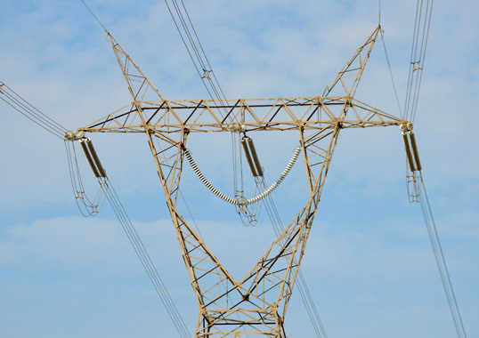
The coastline in Peru experiences scarce rainfall and is affected year round by winds that blow salt particles inland and deposit these on power system structures and components. As a result, porcelain and glass insulators operating in these areas have historically had to be cleaned frequently to avoid pollution flashovers.
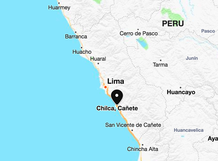
Polymeric insulators were first installed about 30 years ago with the hope that they would help reduce the high cost of insulator washing. A relatively high number of mechanical failures due to brittle fracture forced the country’s TSO – Red de Energia del Peru (REP) – to re-evaluate this strategy. Starting in 2009, RTV coated glass insulators began to replace polymeric types on lines in problematic coastal areas, particularly around the city of Chilca, south of Lima.
INMR visited one of the most important of these lines to report on installation of new RTV-coated glass insulators.

500 kV Fénix-Chilca Line (L5011)
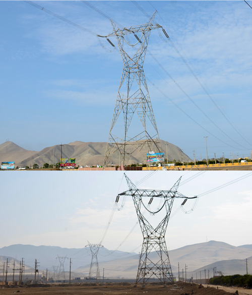
The 500 kV L5011 line connects the 580 MW Fénix Generating Substation to the Chilca Substation. Despite having only 23 towers and being only 7.5 km in length, this line is considered particularly important since it operates in an area characterized by heavy marine pollution combined with high humidity, especially during winter. Moreover, failures on this line could result in situations of service unavailability along with high penalties. Only 28 months after it was first commissioned, high discharge activity was already detected leading to a decision to clean the line’s insulators. About 18 months later, high discharge levels were observed once again.
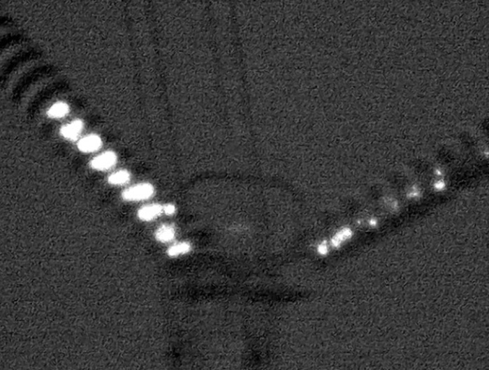
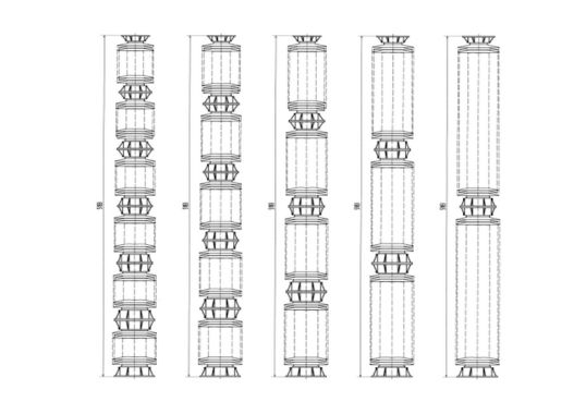
Past investigations conducted to arrive at the optimal frequency to clean coated insulators on this line based on cost and risk found a 12-month cycle to be the best choice. Subsequently, nighttime inspection carried out in March 2019 revealed that half of all insulator strings cleaned 12 months earlier already showed presence of discharge activity (effluvia) that ranged between Grades 2 and 3 (see Fig. 3). This indicated that the strings needed to again be cleaned. Had this same inspection been done during a season with only medium humidity levels, once winter came with its higher humidity, effluvia would likely have reached greater levels, possibly leading to insulator failures.

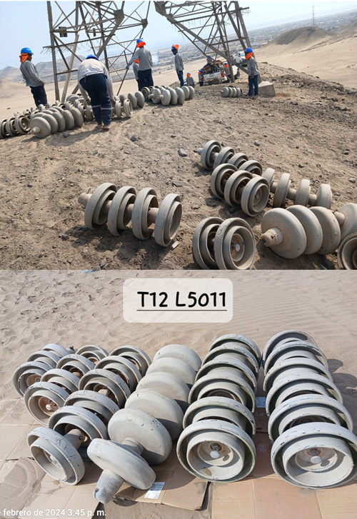
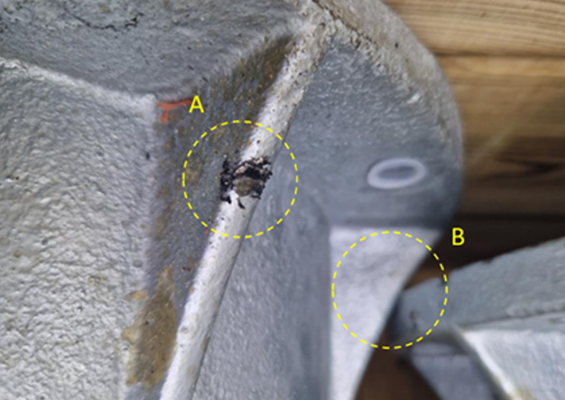
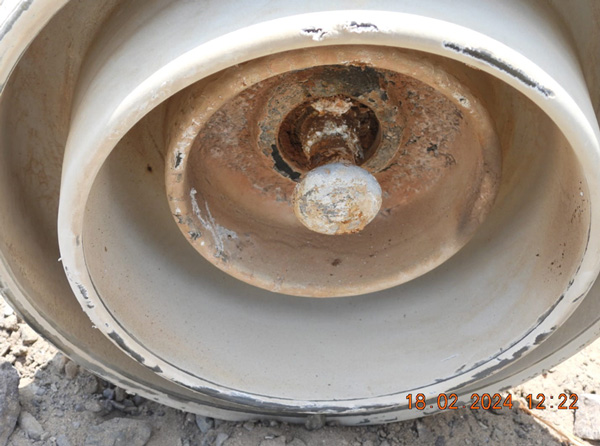
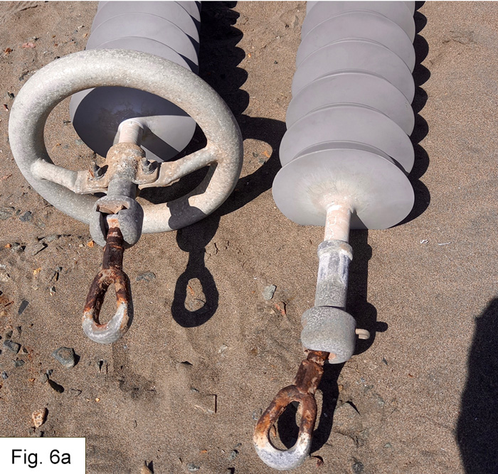
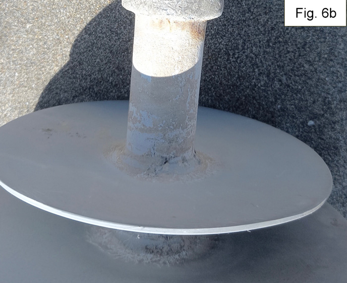
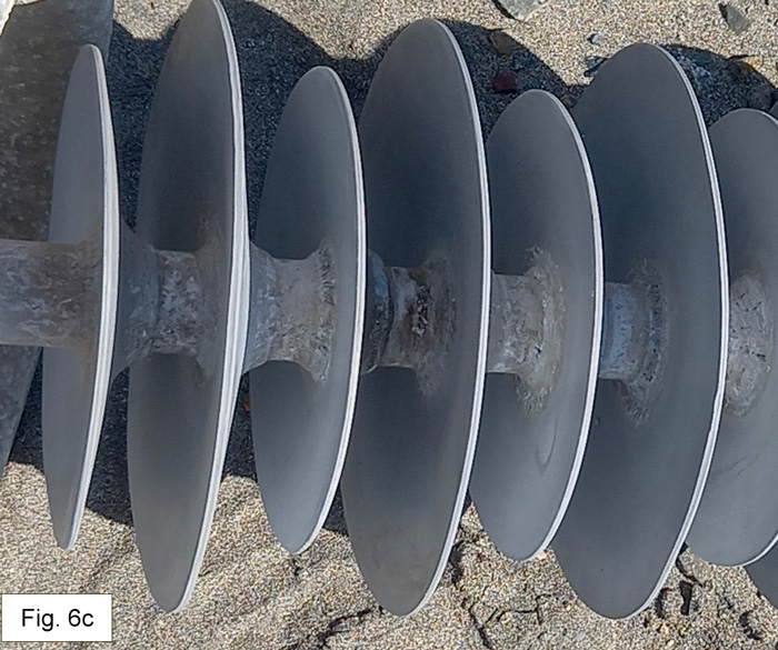
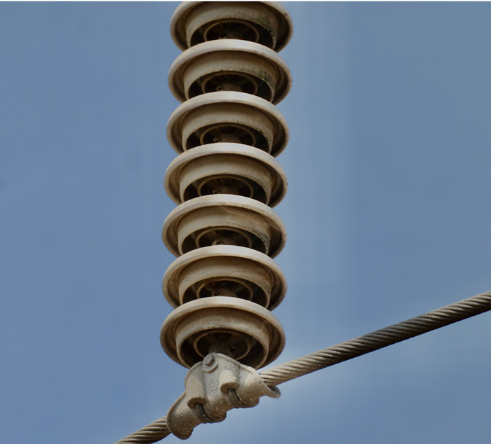
In mid-February 2024, a decision was made to replace all the coated glass insulators on both outer phases of L5011 and also all the polymeric long rods that had operated in the center phase. This work was completed over an allowed shutdown period of 4 days. The pre-existing coated insulators, which had been in service for only about 4 years, already showed evidence of severe degradation of the coating, particularly in the area near the pin. Similarly, the polymeric types removed from the center phase showed start of erosion processes, particularly at the live end. Polymeric insulators had been selected for this phase due to relatively high glass shatter rates observed in the past. But this strategy has now been abandoned in favor of applying coated glass insulators on all phases.
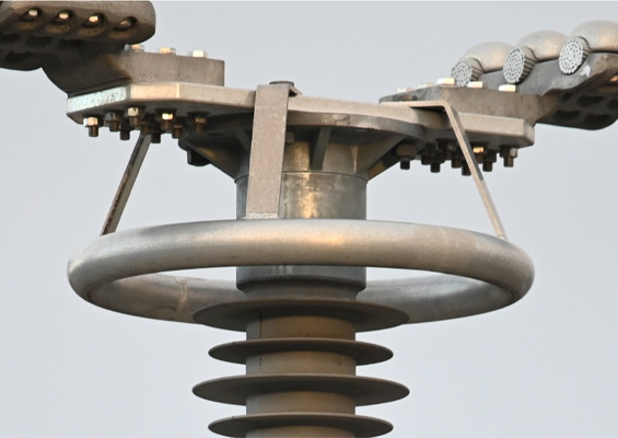
(Photo courtesy Samuel Arturo Asto Soto).

(Photos courtesy Samuel Arturo Asto Soto).
Engineers at REP explain that there are two different maintenance strategies that can be applied when confronted with a line such as L5011 that experiences particularly heavy pollution that can fall outside the limits found in existing international standards. One is to replace all the insulators every few years without question; the other is to selectively replace insulators only when inspection reveals that they are nearing their end-of-life.
The answer as to which strategy is more effective will depend on the zone in which a line operates. In the coastal zone of L5011, for example, the strategy of inspecting and replacing when needed is deemed more suitable for RTV-coated glass insulators while the strategy of replacing regularly, without need for inspection, has been regarded as more suitable for polymeric types. This is the conservative approach.

RTV coated glass insulators are also applied on REP’s nearby 220 kV lines. As with the 500 kV L5011, these insulators need to be manually cleaned on a regular basis, which can change by line section. For example, due to varying microclimates, even across relatively short distances, some sections are manually cleaned each 4 years while others are cleaned every 6 years. The decision on optimal cleaning cycle will depend largely on level of discharge activity detected during night vision inspection.
One aspect to be considered when it comes to such maintenance operations is that experience has shown that RTV coatings start to degrade from the manual cleaning process. That means that frequency of cleaning only increases over time. When it becomes necessary to clean RTV coated insulators each year is the time that these should be replaced with new units.
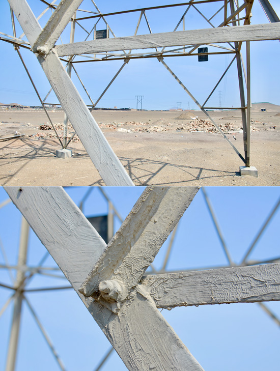
The highly corrosive coastal environment around Chilca also impacts 500 kV and 220 kV tower structures. Those with steel components need to be protected again corrosion using specialized treatments that increase costs. Given this, new structures are preferred to be of wood. However, analysis has found that is still not cost-effective to replace existing steel structures with wood.
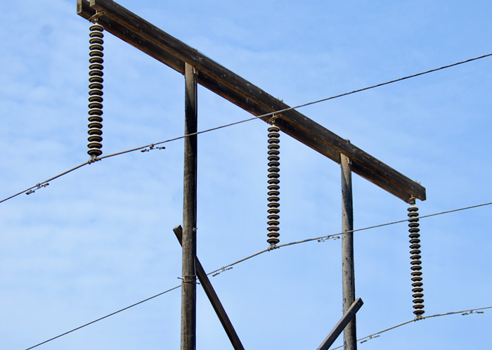
Although REP has decided against continuing to apply new polymeric insulators on its lines in Chilca, other overhead transmission lines in the area operated by other electricity suppliers continue to feature them, often in tension applications.
![]()
![]()