The need for an updated technical review of pollution testing of insulators made from hydrophobicity transfer materials (HTM) originated during discussions held at the 2019 INMR WORLD CONGRESS in Tucson. Speakers at this event emphasized the need for greater guidance on practical application of artificial pollution tests for these types of insulators. Indeed, a new IEC TC 36 63414, has worked to develop a new standard called: “Artificial pollution tests on high-voltage insulators made of hydrophobicity transfer materials to be used on a.c. and d.c. systems”.
This edited contribution to INMR by Igor Gutman presented a comprehensive review of this topic by diverse international experts representing manufacturers, users, consultants and researchers. The aim was to summarize the state-of-the-art of pollution testing of HTM insulators across the globe.

Although two standard pollution tests for ceramic insulators (i.e. Solid Layer and Salt Fog) are specified in IEC 60507 for AC application and in IEC 61245 for DC, HTM insulators are not within the scope of either standard. Given this, IEC 60815-3, which is intended for dimensioning polymeric (composite) type insulators under polluted conditions, only states that in the absence of recommended tests, these can be agreed upon between user utility and manufacturer. This allows for the option that testing HTM insulators could require investigation under both hydrophilic and hydrophobic states. A similar approach is followed for DC dimensioning of polymeric insulators in IEC 60815-4.
The first CIGRE document on this topic (Technical Brochure (TB) 142 published in 1999) presented a historical review of pollution test methods for polymeric insulators. A subsequent CIGRE TB 158 appeared in 2000 and reviewed accumulated knowledge on polluted insulators. Test procedures for polymeric insulators were summarized in a short paragraph. CIGRE TB 361, published 8 years later, was dedicated to pollution dimensioning of insulators for AC and a special Appendix for laboratory test methods for polymeric insulators was included.
A modified version of the Solid Layer Test was outlined and considered testing various levels of hydrophobicity from ‘worst’ through ‘intermediate’ to ‘best’. In 2011, two other CIGRE TBs (455 and 481) were issued and both referred to pollution test methods for polymeric insulators used in practice, mostly for testing under natural pollution. The salt fog test using the rapid procedure (Quick Salt Fog) and the modified Solid Layer Test were recommended for polymeric insulators. CIGRE TB 518 was published in 2012 and dedicated to pollution dimensioning of insulators for DC. It mentioned that several organizations have utilized modified test methods based on existing standards for ceramic insulators.
The first detailed description of an entirely new test method arrived in the long-anticipated CIGRE TB 555 (published in 2013) with its pre-conditioning procedure before pollution application, which included pollution by dry kaolin powder. Two days of elapsed time between the pollution and voltage test was proposed to simulate recovery of hydrophobicity. According to TB 555, while this procedure met CIGRE/IEC requirements for testing, several aspects warranted further consideration. Among these was wetting rate and applicability for DC.
A published document on this issue, i.e. CIGRE TB 691, investigated aspects of rapid methods for pollution testing of ceramic as well as composite insulators for both natural and artificial pollution. The conclusion was that the Rapid Flashover Test (simulating solid layer pollution) and the Quick Flashover Test (simulating wet salt fog pollution) can both be applied for ceramic and for composite insulators and for both AC and DC.
In short, CIGRE recommendations can be summarized as follows:
1. Both Modified Solid Layer and Salt Fog Procedures are applicable;
2. Different hydrophobicity surface conditions should be considered.

Pollution Testing of HTM Insulators
Experience from Sweden
Test Method
The HV laboratory at STRI in Sweden (now Hitachi Energy) has been at the forefront of developing pollution test methods. Initial focus since 2000 was on test methods that do not require conditioning of polymeric insulators, e.g. the Dry Salt Layer Method and the Dust Cycle Method. Since 2005, STRI began using modifications of the Solid Layer Test from IEC 60507, with addition of pre-conditioning for pollution testing of HTM insulators. This method, based on pre-conditioning by dry kaolin, was finally developed and has since been used. Elapsed time between pollution and voltage testing to simulate recovery of hydrophobicity was typically 2 days for composite insulators and 3 days for RTV-coatings. After this, the voltage for flashover tests was applied either by the Up-and-Down or the Rapid Flashover Procedure.
Practical Applications
Many test results were obtained and used in the statistical dimensioning procedure included in IEC 60815-1 (see illustration of the stress/strength concept in Fig. 1 left). A cumulative distribution function describing the strength of the insulation is normally obtained via laboratory tests. Fig. 1 (right) presents typical laboratory results in the form of a graph depicting the 50%-flashover voltage gradient (50%-flashover voltage divided by insulation length) versus SDD. The strength curve (Fig. 1 left) can be created based on this pollution flashover curve and standard deviation of flashover voltage.
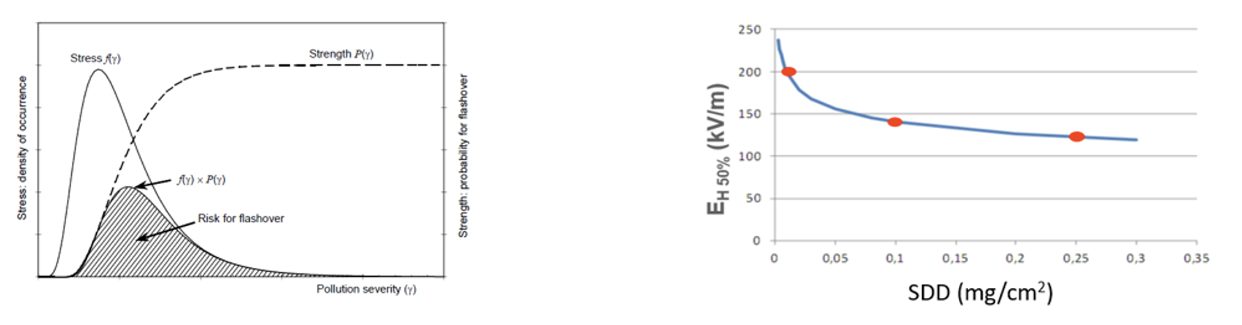
(right) illustration of typical laboratory-based pollution performance curve used as input to stress/strength concept.
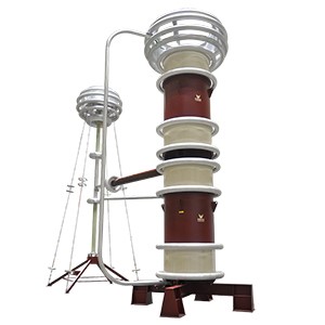
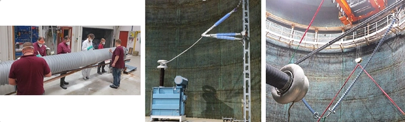
Several collaborative international projects have used this stress/strength concept supported by the flashover voltage curves shown in Fig. 1 using the above test procedure (illustrations are shown in Fig. 2), e.g.:
• South Africa: Refurbishment of AC and DC OHLs in Western Cape. The re-installation was completed and the network has been performing well;
• Norway: A feasibility study was done to upgrade a 300 kV AC OHL to DC, also involving selection of insulation for a new ±525 kV DC OHL, which is now in full operation;
• Sweden: Refurbishment of a 400 kV AC substation;
• United Kingdom: Dimensioning for a new 400 kV AC OHL with T-Pylon towers, where a diamond-like insulation structure of silicone rubber insulators is used.
Experience from France
Test Methods
Sediver operates two high voltage laboratories in France, both having pollution testing capabilities and practical experience in IEC salt fog and solid layer test methods as well as their modifications up to 350 kV AC or DC. The background of this company with polymeric insulators and the growing interest in silicone-coated (RTV) glass insulators has generated growing experience in pollution testing of HTM insulators as well as development of techniques and procedures for pollution testing. However, the protocols for conducting these tests must be described precisely. Differences between findings by laboratories highlight the urgent need for standardization across this industry.
Lessons from Salt Fog Tests
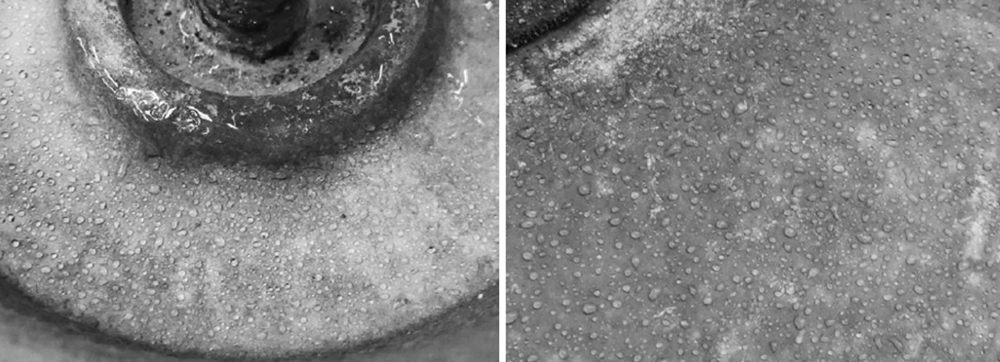
Strict adherence to the Salt Fog Test method from IEC 60507 for HTM materials raises the question of what pre-conditioning is required by the standard. In most cases, the initial phase requiring flashovers will alter hydrophobicity to a certain degree. This can result in discrepancy between some test results and also the real condition of insulators in service, which likely preserve some HTM property along the string (see Fig. 3 for RTV-coated insulators returned from the field and Fig. 4 for silicone rubber apparatus insulators measured directly in the field). This question is under discussion within IEC TC 36 63414.
Lessons from Solid Layer Tests
This test method requires special care in preparation and deposition of the layer as well as consistency in approach, i.e. with or without a rest time to allow for some transfer of hydrophobicity through the pollution layer. The entire concept behind the superior performance of HTM materials in this case relies on the ability of the insulator surface to transfer Lower Molecular Weight (LMW) components but this process is not instantaneous. Without this consideration, pollution testing of HTM insulators is essentially useless. Several details are important:
• Preparation of the surface to enable the pollutant to remain on the surface with consistent surface levels of ESDD and NSDD, as desired;
• Rest time to enable at least some transfer of the hydrophobic property into the pollution layer;
• Test procedure for voltage application to determine the withstand or flashover performance of the insulator (50%-flashover voltages, i.e., U50% are preferred).
Generally, Sediver has been performing pollution tests in line with CIGRE TB 555 and has also customized a technique that produces consistency with no need for “repairs”. This is not a dip but rather a spray technique based on automatic rotation of the test specimen with the slurry established at given viscosities by controlling temperature. Another technique (i.e. the Spray Deposit Airborne Method, “SDAM” developed by Sediver) simulates service representative wind-driven dust deposit using nozzles that generate a cloud of contaminants in a chamber. The contaminant progressively accumulates on the insulator in a consistent layer and the structure of such a solid layer is more representative of actual service conditions. This method also directly allows for CUR (top/bottom) variations, thereby avoiding approximation linked to correction factors, as currently described in IEC 60815.
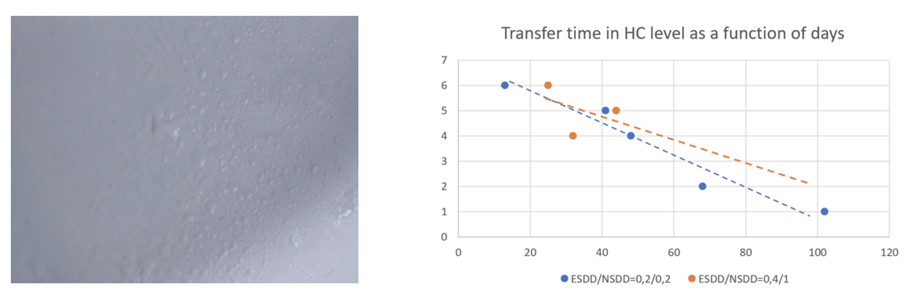
Typically, the average accepted rest time between contamination and testing is 2 or 3 days, although this is the commonly accepted strategy for pollution layers that are not too thick. There is a real challenge when heavy or very heavy pollution levels are required, starting with NSDD > 0.2 mg/cm2. The HC on the top of an artificially polluted silicone surface with a NSDD 1 mg/cm2 after 26 days is HC 6 (see Fig. 5). If recovery of hydrophobicity is estimated on the surface of the pollution layer for such thick layers, this will take 100 days (see Fig. 7). Today, there is still no consensus on what is most suitable for testing such heavy pollution layers. Transfer time can also differ with application method.
Several tests by different laboratories have shown the benefit of using a Quick or Rapid Flashover Method, which allows for relatively easy and fast knowledge of the critical voltage levels for any given pollution condition. Using such methods to obtain a relatively precise window on where pollution performance becomes critical is preferred. However, sometimes the classical Withstand/Flashover Voltage is found to be higher than the results estimated through any Rapid Method. There are also indications that the average U50% found in the Rapid Method is similar to the maximum withstand value from the Up-and-Down Test. This should be further investigated.

Experience from Germany
Experience with Housings for Apparatus Insulators
Composite (HTM) housings are now a widespread solution implemented at electrical grids worldwide and are often preferred in severe environments because of superior pollution performance versus porcelain insulators. The design of composite housings depends mainly on pollution level, diameter, shed profile, material and creepage distance. To achieve optimal design, one must consider:
• possible shed bridging due to rain;
• preventing local short circuiting between sheds,
• aiding self-cleaning;
• avoiding pollution “traps”; and
• limiting local electric field stress.
The pollution performance is always the dimensioning case for DC applications.
The following deals with DC pollution tests and completes previous studies. Several artificial pollution tests were performed at FGH Engineering & Test (part of CESI Group) in cooperation with Siemens Energy and the Bushings Div. of GE Power Grid Solutions in Italy. The test objects were composite insulators and testing included both the Solid Layer Method and the Salt Fog Method. The intention was to verify the expected behavior of insulator designs with different housing materials under varying types and levels of pollution. The average diameters of the housings that were tested were in the range 417 to 875 mm.
Test Methods
In the Solid Layer Method, pre-conditioning of the insulators and the test procedure were adjusted based on the method from CIGRE TB 555. To pollute the hydrophobic housing material, a thin layer of dry kaolin powder was applied on the insulator surface before application of the main pollution layer. The main contamination of the insulator surface was from a mixture of kaolin, water and sodium chloride. After a defined drying period of 20 to 48 h, the polluted insulator was placed into the test chamber and steam fog was used to wet the pollution layer. During the tests, voltage was applied according to the rapid procedure. For the Salt Fog Tests, there was no additional preparation or pre-conditioning of the insulator surface. The test procedure was also based on the rapid procedure.
Lessons from Solid Layer Tests
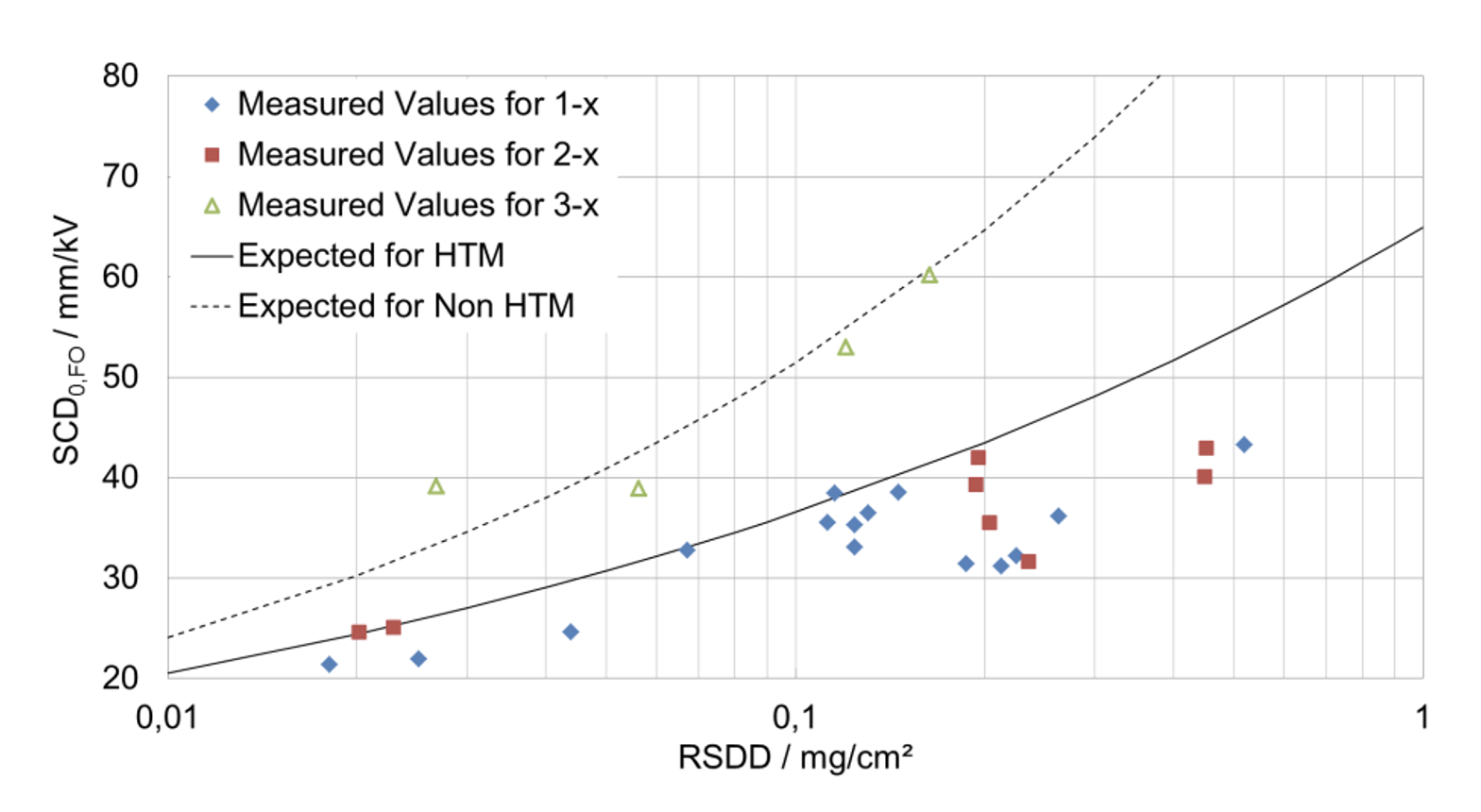
For purposes of comparison, the many different results from these DC tests according to the above procedure were normalized for both flashover voltage and pollution severity. Flashover voltages were presented in SCD0, FO format, which means flashover specific creepage distance corrected for diameter. Pollution severity was presented in RSSD format, which is SDD corrected by NSDD. Fig. 6 illustrates the results and compares these with the recommendation in IEC 60815-4.
Most of the results obtained for HTM insulators using the results of pollution testing were in line with IEC recommendations or even allowed for shorter insulators – especially in more heavily polluted areas (only for insulator 3 was consistently lower flashover performance obtained, as typical for non-HTM insulators). This is an important practical conclusion since many users and manufacturers believe that dimensioning based on direct pollution testing of HTM insulators can only lead to requirements that are higher than recommended by IEC.
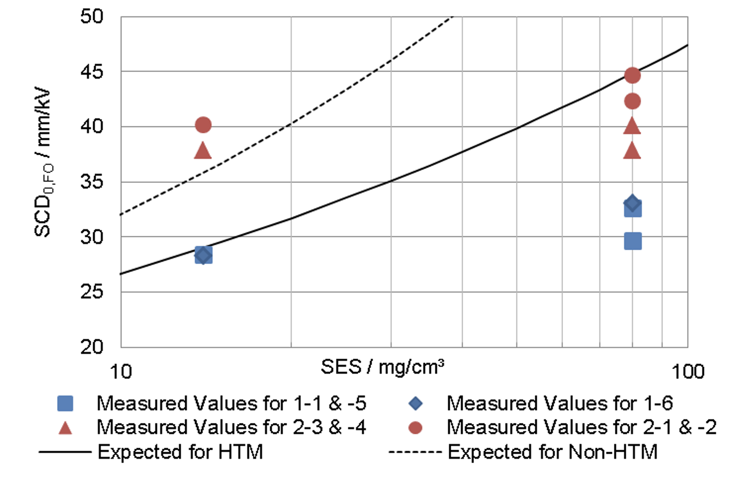
Lessons from Salt Fog Tests
Fig. 7 shows the results from the Salt Fog Tests using the same normalization procedure as for the Solid Layer Method. However, here dimensioning for lower pollution based on direct testing sometimes requires a higher creepage distance than recommended by IEC. By contrast, insulators can be much shorter for higher pollution than recommended by the IEC. These results under DC voltage showed that the recommendations of IEC 60815-4 for the Salt Fog Method require additional research in regard to insulators with large diameters.

Experience with Overhead Line Insulators
AC and DC pollution design of HTM insulators for overhead lines, based on pollution testing, was performed in Germany over the past decade. In most cases, the Solid Layer Method was applied because the sites of greatest interest were inland. Some utilities with lines close to the North Sea also used the Salt Fog Test method, mostly as a withstand test. In special cases (e.g. 420 kV lines and 400 kV AC/DC Ultranet), the statistical method for insulation dimensioning was applied. As part of this method, two or three representative points with different pollution severities were selected and flashover tests were performed at these points (normally by Up-and-Down voltage application with 10 valid points). Tests were performed at AC or DC test voltages depending on the respective application. Pollution flashover performance curves (flashover voltage over SDD) were derived for these applications and implemented into design software used for pollution performance design of insulation.
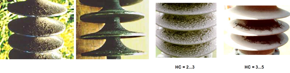
In general, experience with pollution on German networks has been diverse. For example, in the past pollution level was estimated as medium to high, in accordance with IEC 60815. But since the mid 1980s pollution level has fallen to between light and medium. For most inland applications, a solid layer deposit is typical for HTM insulators (see Fig. 8). Hydrophobicity levels on the often thick industrial pollution layers on samples removed from service was normally in the range of HC 3 to HC 4.
This service experience confirmed that the dynamics of hydrophobicity need to be simulated in any representative pollution test. Given this, pollution tests in some cases were performed with the polluted surface adapted to HC 3 to HC 4 to simulate pollution performance under typical local service conditions. Such adaptation was based on visual HC evaluations however discussions are ongoing as to which criteria to apply to best simulate electrical performance of HTM insulators in service. Aside from visual estimation of HC using the spray method in IEC 62073, electrical conductivity of the pollution layer penetrated by LMW components as well as static contact angle and receding angle, etc. are all under discussion.
Experience from Italy
Background
Pollution tests on composite insulators began in Italy at CESI Laboratories during the 1970s, along with the first installation of composite insulators on AC lines. These investigations continued in the 1980s with focus on pollution performance of composite insulators for DC applications. Pollution tests were carried out on composite insulators when new, after severe laboratory ageing and on insulators removed from service. Generally, these tests were performed in Salt Fog with a Quick Flashover Procedure. A few Solid Layer Tests were conducted by RSE, after inheriting part of the CESI Laboratory, using the procedure proposed in CIGRE TB 555.
More recently, systematic tests with Salt Fog (Quick Flashover Procedure) and Solid Layer (Rapid Procedure) were made on composite insulator housings of large diameter. This was done in collaboration with different manufacturers and performed by FGH Laboratory, part of the CESI Group. Because most of the comprehensive Italian experience is with the Salt Fog Quick Flashover Method, only this is presented in the following.
Application of Quick Flashover Salt Fog Test
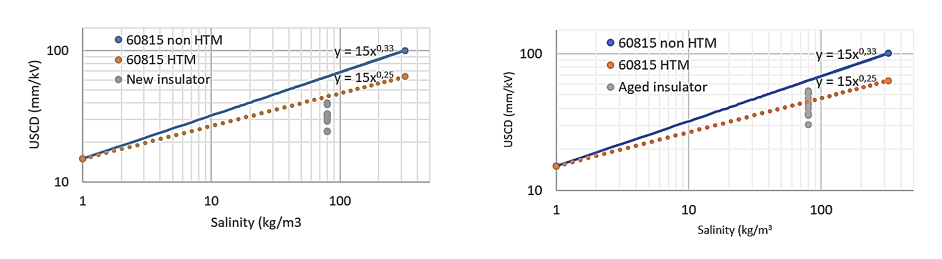
Fig. 9 presents results of pollution tests under AC voltage obtained after 3000 h ageing tests (artificial ageing multi-stress ENEL/CESI test) using salinity of 80 kg/m3 expressed as a function of Unified Specific Creepage Distance (USCD). These findings confirm the expected superior pollution performance versus ceramic insulators.
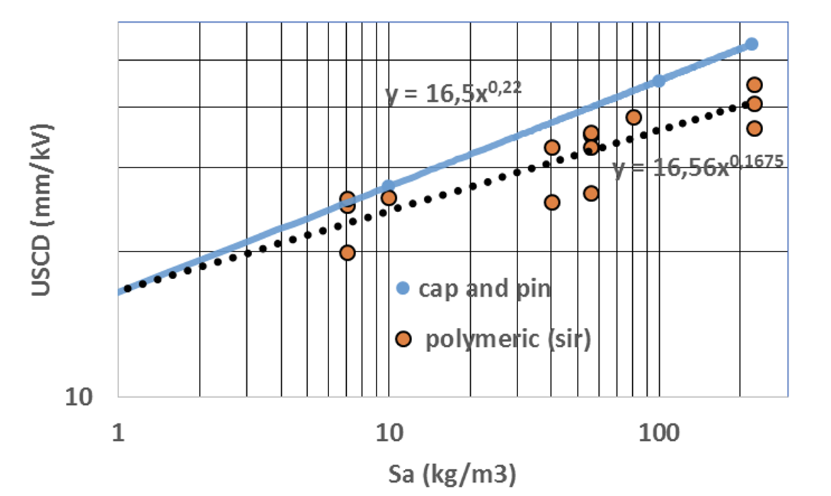
Quick Flashover Methods were also applied to evaluate composite insulators of different types and materials at DC voltage. Fig. 10 presents results of these tests at a salinity of 80 kg/m3 as a function of USCD along with present IEC recommendations. In the case of all silicone rubber insulators, recommended USCD based on testing is remarkably lower than for cap & pin insulators. However, while the non-aged insulators required lower USCD values than those suggested for composite insulators by IEC, insulators after 3000 h ageing required USCD values that corresponded well with IEC recommendations.
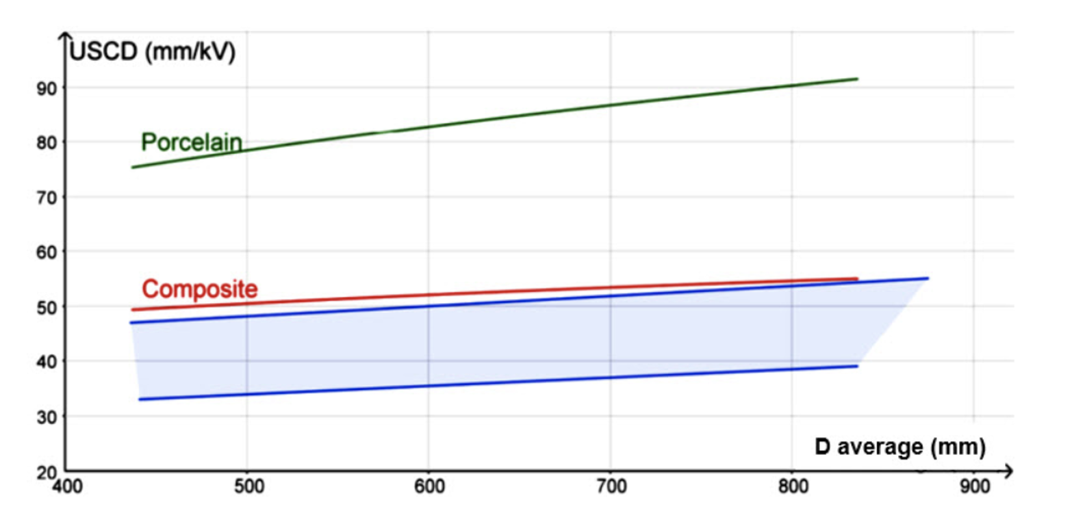
Similar results were also obtained for HTM housings for bushings. It was shown that, based on results of pollution tests, HTM insulators can be dimensioned in a more optimal way than by applying those recommended by the IEC. For example, tests on large diameter composite insulators under DC voltage confirmed that dependence of USCD on insulator diameter for HTM insulators is much lower than for ceramic insulators (see Fig. 11).
Experience from Czech Republic
Background
Pollution tests on ceramic and composite insulators started at EGU-HV Laboratory in the Czech Republic almost 15 years ago. Practical results obtained using the Quick Flashover Salt Fog Test Procedure have already been summarized in CIGRE TB 691. The focus below is therefore on the procedure based on Solid Layer Test Method.
Test Method for Solid Layer Test
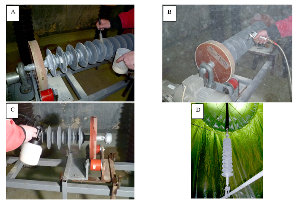
The test procedure followed CIGRE TB 555 and consisted of application of dry kaolin and blowing off any excess, followed by application of contamination by spraying (see Fig. 12).
Experience from Japan
Background & Test Method
Various test procedures have been tried in Japan for HTM insulators exactly as had earlier been conducted for ceramic insulators. These procedures included:
• Fog withstand test (Solid Layer Method as per IEC 60507, Procedure B, and JEC);
• Equivalent fog method (as per JEC);
• Repeated flashover method (a traditional way to test and described in JEC Appendix.
In the past, the Equivalent Fog Method was adopted for non-HTM (i.e. ceramic) long rod insulators since this yielded similar results to the Fog Withstand Test Method but with much shorter testing time. However, the Equivalent Fog Test results for HTM insulators tended to give the same flashover results as for ceramic non-HTM insulators. This is because such tests do not simulate the influence of hydrophobicity on flashover performance. Therefore, the need for correction of test results for HTM insulators is now under discussion among Japanese experts.
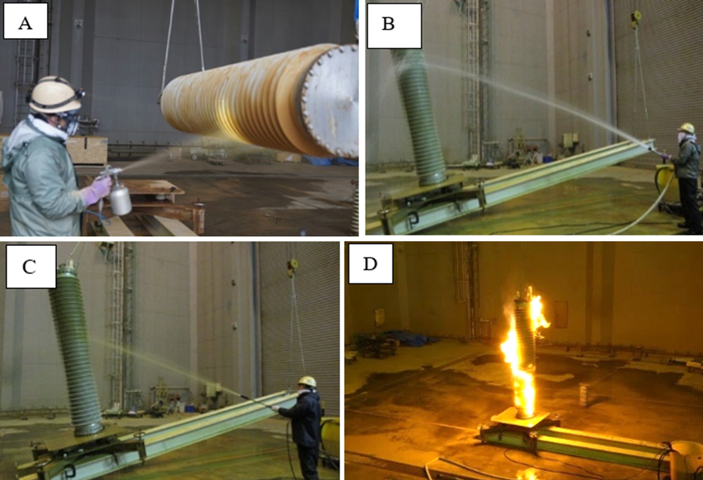
The Equivalent Fog Method for HTM insulators is performed with a pre-conditioning procedure. The main artificial pollution consists of a suspension of Tonoko and salt, which is normally applied by a flow-on process. Testing starts before drying of the pollution layer and voltage is increased gradually until flashover occurs, usually within 0.5 to 3 min after contamination. Fig. 13 illustrates the Equivalent Fog Test procedure being applied to an HTM hollow core insulator.
Application of Test Results
Results from these pollution tests have been directly adopted for practical selection of HTM insulators in both clean and polluted service areas. However, loss of hydrophobicity has been reported under rapid pollution conditions. Moreover, the Japanese environment is characterized by warm and humid conditions and biological growths such as algae are often observed on HTM composite insulators, independent of pollution severity. A surface covered by algae will lose hydrophobicity and lead to lower surface resistance compared to standard contamination by Tonoko. To take this into account, it has been proposed to define design NSDD as 3 times higher than for non-HTM ceramic insulators. However, to allow for some recovery of surface hydrophobicity in service, the specific creepage distance for HTM insulators can be reduced to 90% in comparison to ceramic insulators.

Experience from South Africa
Background
For many years, Eskom has followed international guidelines when selecting transmission and distribution insulators for use in polluted environments. The proliferation of non-ceramic (i.e. polymeric, resin and coated) insulators in recent years has led to their increased application in South Africa in spite of concerns about their long-term electrical performance and material longevity.
Eskom’s experience has led engineers to conclude that only field testing will expose any insulator to a realistic combination of pollution and ageing. Given this, the 11-132 kV Koeberg Insulator Pollution Test Station (KIPTS) was established to determine ageing performance of insulators under natural pollution. Results from KIPTS have also been complemented by pollution tests on artificially and naturally polluted insulators, mainly to compare different insulation options. Unfortunately, severe sand dune movement required KIPTS to be decommissioned and a new insulator pollution test station (11-400 kV) is planned. In the meantime, the following pollution performance test approach is being used to help qualify MV and HV insulation.
Test Approach
Eskom’s approach is based in general on Approach 2 (“Measure and Test”) from IEC TS 60815-1. Pollution performance curves are required, only from recognized, independent laboratories, on test specimens having identical insulation to that of an insulator to be supplied for the network. These are U50% flashover voltage curves (using the Rapid Flashover Test Method) at three pollution levels of SDD, with NSDD of ≥ 0.1 mg/cm2 and using:
• the Solid Layer Test method for glass and porcelain insulators, according to IEC TS 60507 and using a spray gun to apply the kaolin composition;
• the Modified Solid Layer Test method (with a pre-conditioning procedure with and without recovery) for polymeric insulators according to CIGRE TBs 555 and 691.
The U50% flashover voltage obtained is then converted into flashover stress along the test insulation length HT as 50%/ (in kV/m) and presented as three-point approximated power law curves versus pollution level (SDD in mg/cm2 as per Fig. 14). The Um is the highest system r.m.s. phase-to-ground voltage that the insulator to be supplied will be subjected to. The insulator will be accepted if 50%/ > m/ in the SDD range:
• 06 to 0.12 mg/cm2 for application in ‘Light’ to ‘Medium’ environments, with minimum specific creepage distance of 20 mm/kV in terms of phase-to-phase voltage;
• 12 to 0.48 mg/cm2 for use in ‘Heavy’ to ‘Very Heavy’ environments, with minimum specific creepage distance of 31 mm/kV in terms of phase-to-phase voltage.
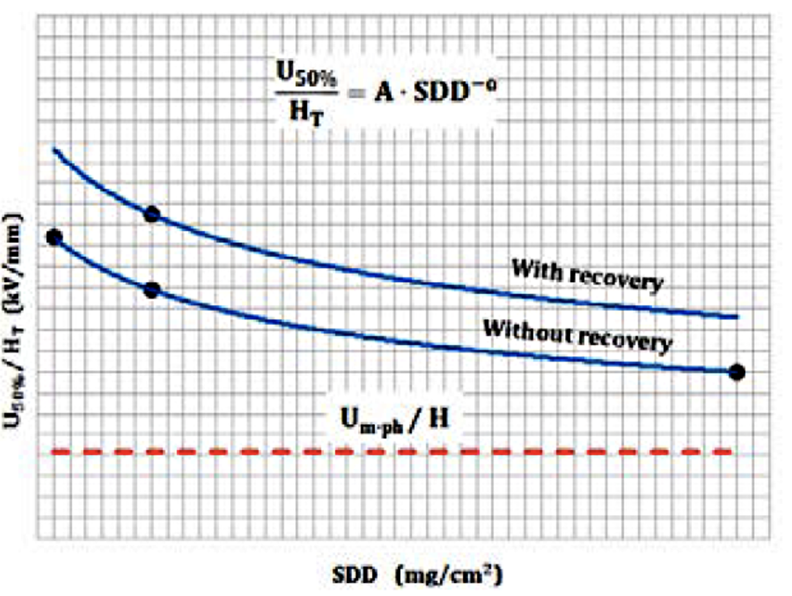
Insulator pollution flashover performance curve constants “A” and “α” should be derived for the equation 50%/ =•DD−. This will be used by Eskom along with Site Pollution Severity values in the statistical approach to optimize insulation selection (as per Annex G of IEC TS 60815-1).
Application of Test Results
Practical applications of the statistical approach for insulation dimensioning (i.e. pollution flashover performance curves mentioned above together with site severity measurements and target outage rate) are summarized as follows:
• Insulation level requirements for new 132 kV and 400 kV outdoor substation;
• Refurbishment of existing 400 kV AC line equipped with glass cap & pin insulators with silicone rubber units. The re-insulation of 21,000 glass cap & pin insulator strings with composite insulators was performed in a short time by live line work and the network in West Cape has since been operating successfully;
• Refurbishment of a 533 kV DC line with composite insulators. Statistical dimensioning using the IST (Insulator Selection Tool) Program and with a given targeted outage rate made it possible to insulate all poles with composite insulators at 40 mm/kV and with a 4712 mm connection length for operation at 533 kV. Refurbishment was completed and the line is now in operation.

Experience from China
Background
Experience with HTM insulators in China has exceeded 35 years and it is estimated that over 9 million composite line insulators are now in service at voltage levels between 110 to 1000 kV AC and ±400 kV to ±1100 kV DC. One of the important reasons for the rapid increase in application of composite insulators in that country has been their excellent pollution performance. As such, research on pollution testing of composite insulators has been ongoing since their introduction. In the late 1990s, an original test method was developed and verified and presently is included in China Electric Power Industrial Standard DL/T 859-2015 as well as in National Standard GB/T 34937-2017.
Test Method
Traditional artificial pollution test methods for ceramic insulators, such as found in IEC 60507, are not deemed suitable for composite type insulators because it is difficult to apply a uniform layer of artificial pollution on the surface of highly hydrophobic silicone rubber material. After continuous attempts, however, this problem was eventually resolved using a pre-conditioning procedure. Before applying the pollution, a dry sponge or soft brush is used to paste a uniform thin layer of dry kieselguhr on the surface of the test insulator. A blower-like device is then used to remove excess kieselguhr, while also enabling a very thin layer of hydrophilic substance to remain attached to the surface. Since the layer of kieselguhr is extremely thin, it does not influence desired NSDD in the main pollution phase. The test insulator can now be easily contaminated by any standard pollution application method, which shall be completed within 1 h after pre-conditioning.
Another challenge has been simulating the hydrophobicity state of the surface. Various non-soluble pollutants were investigated to choose a material that best simulates different levels of hydrophobicity. These included kieselguhr, kaolin, Tonoko, SiO2, metal oxides (e.g. ZnO, Fe2O3, Al2O3) and inorganic salts with different solubilities, such as BaSO4, CaSO4, ZnSO4, (NH4)2SO4, K2SO4, NH4Cl, CaCl2, NaCl and KCl. The most commonly used pollutant in China has become a combination of kieselguhr/kaolin and NaCl.
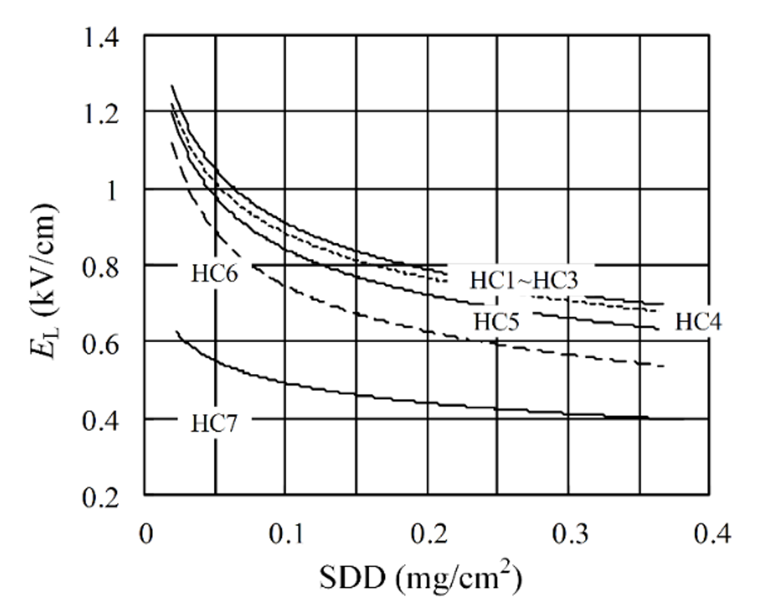
A pollution layer based on kieselguhr is much faster in recovering hydrophobicity than one based on kaolin. For example, after only 2-4 h of ‘rest’ time, the contact angle (CA) on the surface becomes higher than 90°. In the case of kaolin, CA remains lower than 90° even after 5 days of ‘rest’ time. As such, different surface hydrophobicity classes for polluted silicone rubber insulators could be simulated – from HC 7 (totally hydrophilic) to HC 1 (completely hydrophobic). Fig. 15 shows the pollution flashover gradient along creepage distance EL over SDD for different levels of HC. Change in hydrophobicity from HC 1 to HC 4 had almost no influence on pollution performance. As hydrophobicity deteriorated, EL gradually decreased. When hydrophobicity became totally lost (i.e. HC 7), the EL curve decreased significantly in comparison to HC 6.
Choosing relevant laboratory pollution severity is another key issue. Based on experience in China, valid for both ceramic and composite type insulators, measured in-service ESDD value cannot be directly translated into SDD in artificial pollution tests. In fact, for many cases of natural pollution, making ESDD equal to SDD will provide different flashover voltages for the same insulators tested under natural and artificial pollution. Correction from measured ESDD to laboratory SDD is therefore very important.
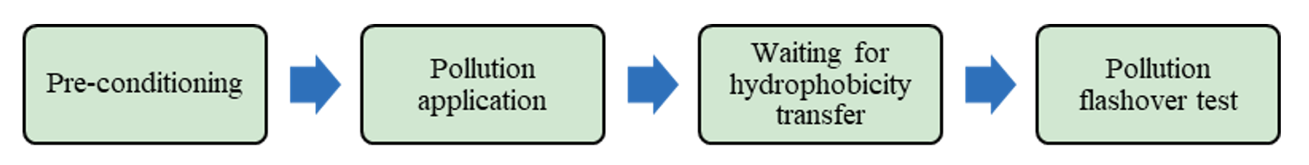
Finally, the test method includes four steps (illustrated in Fig. 16):
• Step 1 (Pre-conditioning);
• Step 2 (Pollution application): Brushing method is recommended for line insulators and dipping method is recommended for insulators with large diameters;
• Step 3 (Waiting for hydrophobicity transfer): Different hydrophobicity levels at the surface of the contaminated insulator can be achieved by applying different pollutants and recovery times;
• Step 4 (Pollution withstand/flashover test): Standard artificial pollution test procedures shall be applied.
Application of Test Results
In China, artificial pollution testing of HTM composite insulators is used for evaluating pollution performance, thus guiding future insulator selection and dimensioning. Practically-speaking, dimensioning is based conservatively on a low hydrophobicity state (i.e. HC 5 to HC 6) to reflect impact of pollution, hydrophobicity reduction and possible ageing.
Two decades have now passed since this artificial pollution test method was first standardized in 2002. At present, this mature method has been fully accepted and is widely being used in practice for evaluating pollution performance and dimensioning of AC and DC silicone rubber composite insulators. Average pollution outage rates for all AC and DC OHLs in China (110 kV to 1000 kV) has decreased by two orders of magnitude compared to the peak of 0.12 outages/100 km·year back in 2001 – even as the total length of OHLs equipped with composite insulators has increased dramatically. This confirms that application of this artificial pollution test method for HTM composite insulators has been a success.
Summary
Results of comprehensive practical experience using artificial pollution tests on HTM insulators across different countries and at different commercial high voltage laboratories makes possible to reject a number of myths and misconceptions:
1. The first myth is that such a test is not necessary. In fact, many countries/laboratories are using it for insulation dimensioning which has then been verified by service experience;
2. The second myth is that it is complicated to create a relevant test procedure. Actually, most countries/laboratories use principles already summarized in two published CIGRE brochures (TB 555 and TB 691) which propose slightly modifications to known standard procedures. Basically, both the Modified Salt Fog and the Solid Layer Test are proposed;
3. The third myth is that practical application of such a test will lead to over-dimensioning. Results from Germany and Italy, in fact, have shown that dimensioning based on test results is in line with IEC recommendations. Even shorter insulators can be proposed based on comprehensive testing. Results from China, widely using pollution dimensioning based on testing, are also well supported by service experience. Application of statistical dimensioning based on laboratory flashover performance also makes it possible to optimize insulator length/creepage. This has been confirmed across several practical projects worldwide.
Table 1 summarizes experience with different test methods across different countries. The colors illustrate which tests are most used in each: GREEN illustrates major experience, YELLOW illustrates other experience.
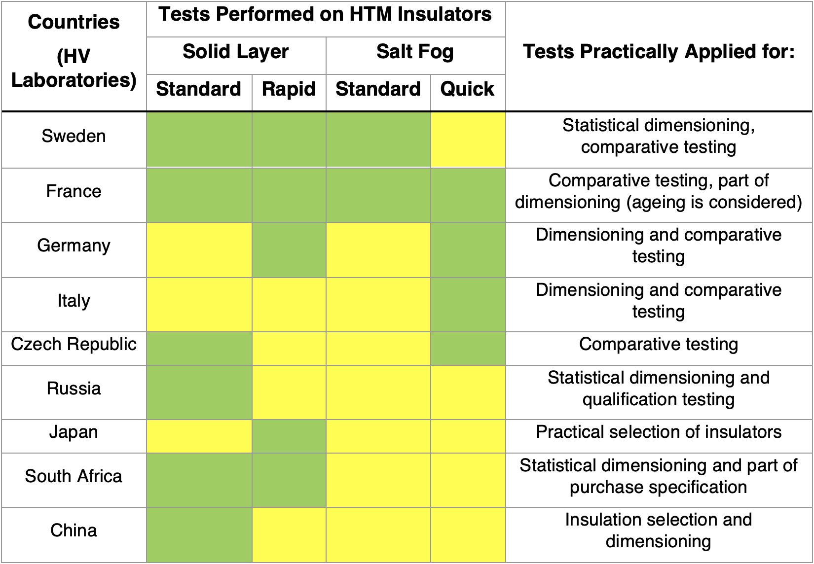
Level of practical application of laboratory pollution tests differs by country:
• China and Russia have already included these tests in their national standards and use them regularly;
• South Africa includes these tests as part of the acceptance process for any new insulator entering the market;
• Many other countries/laboratories use these tests for dimensioning and comparison purposes, exactly as has been their main purpose for ceramic insulators. There is no intention to require these tests as type tests.
The intrinsic feature of HTM insulators, i.e. surface hydrophobicity, should be included in any future pollution test method. The test procedures described above are similar to those for ceramic insulators and two basic procedures are preliminarily proposed:
1. Modified Salt Fog Procedure, as described in CIGRE TB 691, i.e., Quick Flashover Procedure. A standard salt fog withstand procedure, which does not significantly influence hydrophobicity level of insulators in the absence of repeated flashovers, would in many cases allow insulators to pass under any salinity;
2. Modified Solid Layer Procedure, as described in CIGRE TB 555 and TB 691, i.e. including preconditioning and elapsed time between contamination and voltage test;
3. Proposals (1) and (2) are basic while the exact test procedure can be slightly different, e.g. using different contaminants (as for ceramic insulators in IEC), different criteria for recovery of hydrophobicity (e.g. on the top or inside the pollution layer), etc. Special attention should be paid to preconditioning (i.e. recovery simulated by transfer time) for very heavy pollution conditions. All these can be finetuned based on discussions within IEC TC 36 63414 that aims to develop a new standard “Artificial pollution tests on high-voltage insulators made of hydrophobicity transfer materials to be used on a.c. and d.c. systems”.
4. It is important to stress that, in contrast to ceramic insulators, HTM insulators cannot be dimensioned based solely on pollution performance since possible ageing must also be considered. But this is a separate issue for another technical review.

References
[1] I. Gutman, P. Cardano, A. Dernfalk, J.-M. George, T. Hayashi, K. Kondo, J. Lachman, S. Li, X. Liang, E. Moal, A. Pigini, J. Seifert, E. Solomonik, W. Vosloo, D. Windmar: “State-of-the-art of Pollution Test Procedures for Insulators with Hydrophobicity Transfer Materials”, CIGRE Science & Engineering, N. 21, June 2021, p.p. 141-169
[2] CIGRE Technical Brochure No. 142, “Natural and artificial ageing and pollution testing of polymeric insulators”, June 1999
[3] CIGRE Technical Brochure No. 158, “Polluted insulators: a review of current knowledge”, June 2000
[4] CIGRE Technical Brochure No. 361, “Outdoor insulation in polluted conditions: guidelines for selection and dimensioning. Part 1: General principles and the AC case”, June 2008
[5] CIGRE Technical Brochure No. 455, “Aspects for the Application of Composite Insulators to High Voltage (≥72kV) Apparatus”, April 2011
[6] CIGRE Technical Brochure No. 481, “Guide for the Assessment of Composite Insulators in the laboratory after their Removal from Service”, December 2011
[7] CIGRE Technical Brochure No. 518, “Outdoor Insulation in Polluted Conditions: Guidelines for Selection and Dimensioning, Part 2: The DC Case”, December 2012
[8] CIGRE Technical Brochure No. 555, “Artificial pollution test for polymer insulators”, October 2013
[9] CIGRE Technical brochure 691, “Pollution test of naturally and artificially contaminated insulators”, July 2017
[10] I. Gutman, J. Lundengård, M. Fairhurst, “Three-phase pollution test of diamond-shaped “suspension” insulator arrangement for T-pylon tower”, 13th INSUKON-2017, Birmingham, UK, 16-18 May 2017, p.p. 233-237
[11] J.-F. Goffinet, I. Gutman, P. Sidenvall, “Innovative insulated cross-arm: requirements, testing and construction”, ICOLIM-2017, Strasbourg, France, 26-28 April 2017, paper 0078
[12] B. Thorsteinsson, K. Halsan, M. Gullo, I. Gutman, “Innovative pollution and ice testing of DC composite insulators for ±525 kV DC line”, ISH-2017, Buenos Aires, Argentina, August 28 – September 01, 2017, paper 156
[13] J.-M. George, S. Prat, C. Lumb, F. Virlogeux, I. Gutman, J. Lundengård, M. Marzinotto, “Field Experience and Laboratory Investigation of Glass Insulators Having a Factory-Applied Silicone Coating”, IEEE Transactions on Dielectrics and Electrical Insulation, Vol. 21, No. 6, December 2014, p.p. 2594-2601
[14] I. Gutman, C. Ahlholm, U. Åkesson, A. Holmberg, D. Wu, L. Jonsson, “Long-term service experience and inspection results of HV equipment made of silicone rubber insulators”, CIGRE Symposium, Auckland, New Zealand, September 14-20, 2013, A3-412
[15] E. Moal, “Experience on Composite Hollow Core Insulators Regarding Pollution Performance”, 6th Conference on Silicone Insulation, Burghausen, June 27 – 28, 2017
[16] E. Moal, V. Bergmann, A. Soergel, “Technical Design Requirements for Composite Hollow Core Insulators Regarding Pollution Performance under AC & DC”, 2017 INMR World Congress, Barcelona, November 5-8, 2017
[17] G. Testin, M. Boutlendj, P. Cardano, A. Pastore, M. Saravolac, M. Sehovac, A. Pigini, “Methodologies for pollution tests on composite housings”, CIGRE-2016, A3-115
[18] C. Neumann, “Betriebsverhalten von Silikonisolatoren (Service experience of silicone rubber insulators)”, ETG Workshop, Berlin, 2003 (in German)
[19] M. Cojan, J. Perret, C. Malaguti, P. Nicolini, J.S.T. Looms, A.W. Stannet, “Polymeric transmission insulators: their application in France, Italy and UK”, CIGRE-1980, paper 22.10
[20] F. Bianchi, G. Marrone, C. Masetti, A. Pigini, “Recent laboratory and field experiences on composite insulators in Italy”, L’Energia Elettrica, N.1, 1983 (in Italian)
[21] G.P. Fini, G. Marrone, G. Gallucci, A. Pigini, “Field experience and laboratory ageing test on composite insulators for overhead lines”, L’Energia Elettrica, N. 7-8, 1984 (in Italian)
[22] S. Bossi, A. Pigini, G.P. Fini, A. Porrino, E. Channakeshava, N. Vasudev, M. Ramamoorty, “Study of the performance of composite insulators in polluted conditions”, CIGRE-1994, paper 33.10
[23] G. Pirovano, P. Omodeo Gianolo, A. Pigini, “Assessment of the pollution performance of composite insulators”, ISH-2013, Seoul, Korea, 25-30 August 2013, OC-1
[24] A. Pigini, R. Cortina, M. Marzinotto, G. Lagrotteria, “Pollution tests on composite insulators: the Italian experience”, ISH-2015, Pilsen, Czech Republic, 23-28th August 2015, paper 367
[25] L.L. Vladimirsky, E.A. Solomonik, N.N. Tikhodeev, I. Gutman, “Methods of statistical dimensioning of the outdoor insulation with respect to polluted conditions”, IEEE PowerTech 2005, St. Petersburg, Russia, 27-30 June 2005, paper 670
[26] W.L. Vosloo, I. Gutman, J.P. Holtzhausen, “Statistical determination of insulator performance at Koeberg insulator pollution test station”, The 5th CIGRE Southern Africa Regional Conference, Cape Town, South Africa, 24-27 October 2005, p.p. 180-187
[27] Russian Standard GOST 10390-2015, “Electrical equipment for 3 kV and above. Test methods of outdoor insulation in polluted conditions”, Standardinform, Moscow, 2016 (in Russian)
[28] Russian Standard GOST 28856-90, “Line suspension long rod composite insulators. General technical requirements”, Publishing house of standards, Moscow, 1990
[29] T. Kawamura, T. Seta, K. Nagai, K. Naito, “DC Pollution Performance of Insulators”, CIGRE- 1984, paper 33-10, 1984
[30] JEC (Japanese Electrotechnical Committee) – 0201, “AC Voltage Insulation Tests”, 1988 (in Japanese)
[31] I. Gutman, J. Lundengård, W. Vosloo: “Development of Time- and Cost-Effective Pollution Test Methods Applicable for Different Station Insulation Options”, IEEE Transactions on Dielectrics and Electrical Insulation, Vol. 21, No. 6, December 2014, p.p. 2525-2530
[32] I. Gutman, W.L Vosloo, L. Appollis, “Example of refurbishment of overhead lines 400 kV at Western Cape after major pollution event in February 2006”, CIGRE-2012, B2-302
[33] S. Narain, V. Naidoo, R. Vajeth, “Upgrading the performance of the Apollo – Cahora Bassa 533 kV links”, CIGRE Session 2012, B2-301
[34] X. Liang, S. Li, “Looking to the Future of Composite Insulators”, World Congress & Exhibition on Insulators, Arresters & Bushings, Munich, Germany, 18-21 October 2015
[35] X. Liang, S. Li, Y. Gao, Z. Su, J. Zhou, “Improving the outdoor insulation performance of Chinese EHV and UHV AC and DC overhead transmission lines”, IEEE Electrical Insulation Magazine, vol. 36, pp. 7-25, 2020
[36] China Electric Power Industrial Standard DL/T 859, “Artificial pollution tests on composite insulators used on high-voltage AC systems”, 2015 (in Chinese)
[37] National Standards of the People’s Republic of China GB/T 34937, “Insulators for overhead lines-Composite suspension and tension insulators for d.c. systems with a nominal voltage greater than 1 500 V-Definitions, test methods and acceptance criteria”, 2017 (in Chinese)
[38] W. Shaowu, L. Xidong, G. Zhicheng, W. Xun, “Hydrophobicity transfer properties of silicone rubber contaminated by different kinds of pollutants”, 2000 Annual Report Conference on Electrical Insulation and Dielectric Phenomena, Victoria, Canada, 2000, pp. 373-376
[39] X. Liang, S. Wang, J. Fan, and Z. Guan, “Development of composite insulators in China”, IEEE Transactions on Dielectrics and Electrical Insulation, vol. 6, pp. 586-594, 1999
[40] Z. Su, X. Liang, Y. Yin, J. Zhou, P. Li, W. Li, “Important correction factors in HVDC line insulation selection”, 14th ISH, Beijing, China, 2005, p. D-61
[41] X. Liang, S. Li, Y. Gao, Z. Su, J. Zhou, “Improving the outdoor insulation performance of Chinese EHV and UHV AC and DC overhead transmission lines”, IEEE Electrical Insulation Magazine, vol. 36, pp. 7-25, 2020