Bushings are highly reliable components. However, if failed, the typical result is extended downtime of a power transformer with heavy financial losses as well as challenges imposed on the system operator to compensate for the lost unit. Most high voltage bushings these days are condenser type – also known as fine-graded or capacitance-graded. They are designed to reduce maximum field stress and optimize field distribution in both axial and radial directions when passing through a grounded transformer enclosure.


Three main technologies for condenser bushings have evolved over the years. The resin bonded paper (RBP) type has been used now for over a century. However, the winding process for this type is typically not carried out under vacuum and air can become trapped inside the core, forming voids after curing. RBP bushings are therefore not guaranteed free from partial discharges and tend to show dissipation factors of 0.5 to 0.7% (compared to ≤ 0.4% for more modern bushing technologies). Some RBP bushings also contain mineral oil for insulation that can cause reliability issues as these units approach the end of their expected service lives. Moreover, since RBP cores are not gas tight, they cannot be used in applications involving SF6 apparatus. Due to all the above, this technology is being phased out.
A second long-established bushing technology is the oil-impregnated paper (OIP) type that, because of relatively low acquisition cost, still dominates today’s market. Here, the condenser core is impregnated with transformer grade mineral oil and placed inside a housing made of porcelain or a composite insulator to seal against moisture ingress. High quality OIP bushings can be manufactured to offer low capacitive losses and be free of partial discharges. However, the condenser core remains in a liquid environment throughout its lifetime and there may be problems of leakage around gaskets. Also, in the event of internal electrical breakdown, high internal pressure can build up quickly, resulting in an explosion.
The state-of-the-art technology for condenser bushings, according to most, is still resin-impregnated paper (RIP). RIP bushings consist of a wound core made from untreated crepe paper, which is then impregnated with a curable epoxy resin. For outdoor applications, a porcelain or composite insulator housing is used. RIP bushings provide a number of technical advantages: being fully dry and pressure-free; featuring a higher temperature class; being partial-discharge free; having low dielectric losses; being fire resistant, and; having outstanding mechanical properties. While usually coming with higher initial cost compared to OIP types, RIP technology can offer lower life cycle cost if reduced maintenance and less need for monitoring are factored in.
Newer technologies have been introduced that are similar to RIP but offer added advantages due to the paper being replaced by synthetic material. Resin-impregnated synthetic (RIS) types are such a technology and these bushings are characterized by low dielectric loss factors (tan δ) – typically below 0.35%. The electrical design and the void-free impregnation process, similar to that of RIP bushings, allows for partial-discharge free operation even at twice maximum phase-ground operating voltage. While initial performance of RIS is comparable to that of state-of-the-art RIP bushings, unlike RIP styles that are vulnerable to ingress of moisture and increase in loss factor if improperly handled and stored, RIS types are immune to this risk. They therefore require less care. Similarly, it cannot be ruled out that high water content in aged transformer oil might penetrate an RIP bushing and impact its performance. RIS bushings will not suffer this risk during operation and this is another of the factors contributing to their higher expected lifetime versus other technologies. Since RIS bushings can be stored without additional costly measures to keep humidity out, they are expected to result in even lower life cycle costs than RIP styles. In this regard, they offer the promise of becoming the preferred choice for utilities whose selection of bushings is based on a long-term philosophy.

Role of Bushings in Transformer Failures
Bushings are among the most critical components of a power transformer and there is ample evidence that they are among the major initiators of failures. On average, the risk of a large power transformer failure is assumed to be up to 1% per year of service. Furthermore, it is estimated that 10% of transformer failures result in serious fire, meaning that this risk is as high as 0.1% in each year of service. Almost 50% of all serious transformer fires are initiated by failure of OIP bushings and these are properly classified as the single leading cause of transformer fires. For example, a past CIGRE Working Group determined that for utilities operating in Germany, Austria, Switzerland and the Netherlands bushings were typically responsible for circa 12% of major transformer failures. This proportion grew to approximately 17%, if the analysis was limited to transformers with service voltages above 100 kV.
Risk Assessment
When performing a proper risk assessment, it is important not only to consider probability of failure but also the impact of damage associated with failure. As an initial systematic approach, it is important to reduce the probability of failure itself. If the failure probability cannot be reduced to an acceptable level (e.g. for economic or technical reasons), the impact of failure should then be reduced to a desired level. Assuming transformer failure rates follow the well known ‘bath tub curve’, failure rate at the beginning and end of a transformer’s life should increase. By performing a thorough factory acceptance test, probability of early failures tends to be significantly reduced since the material will be ‘pre-stressed’. It has also been shown that, towards the end of its expected lifetime, the probability of transformer failure increases rapidly. Probability of serious fire initiated by a transformer failure depends on bushing technology involved. In this regard, OIP bushings have a considerably higher likelihood of causing a serious transformer fire compared with RIP bushings. Also, the choice of material of the outdoor insulator influences the severity of any failure.
Ageing & Breakdown Mechanism of Transformer Bushings
Based on long-term field experience with well-known bushing technologies, the following is the approx. distribution of identifiable root causes requiring overhaul or replacement of a bushing:
• 80% leakage (only for bushings containing oil within the insulation)
• 13% deterioration of insulation
• 7% mechanical damage (mainly to porcelain insulators)
Moreover, ageing of a transformer bushing is influenced mainly by the following factors:
• High ambient temperatures & temperature changes
• High & frequent load cycles (e.g. pump storage power plants)
• Overvoltage/transients (switching, lightning, harmonics)
• Leakage → moisture ingress
• Oil leakage (OIP only) → loss of insulation/dielectric properties
• Corrosive contaminants in oil (for OIP only)
• Capillary cracks (RBP types) → partial discharges
• Partial discharges
A comprehensive assessment of a bushing’s condition is often limited to a qualitative evaluation. This is the case since, for most installations, the above factors have not always been systematically tracked. Under normal conditions, life expectancy is assumed to be >25 years for RBP bushing and >30 years for OIP and RIP bushings.
Of course, assessed ‘end-of-life’ is a statistic. It does not mean that there will be an immediate bushing failure after reaching the end-of-life but rather that probability of failure increases. In fact, there are reports of RBP bushings that have been in service for more than 35 years without problems. Yet, it must also be considered that an aged insulation system is less immune to high external voltage stress – in particular when exposed to nearby lightning strikes or excessive transient switching operations. While similar incidents may not have caused problems in the past, the same stress when aged can initiate harmful partial discharges, which finally result in breakdown.

Managing Transformer Bushing Fleet
Cost-effective prioritization within an overall bushing fleet replacement strategy requires considering a variety of factors, e.g. not only the condition of the individual bushing but also the impact on the system and potential collateral damage to equipment and personnel in the case of a transformer failure. Below is a straightforward approach that can serve as a guideline on how to set up a bushing fleet management strategy, with primary focus on reducing the above-mentioned risks.
Step 1: Identification & Clustering of Installed Bushing Fleet
Traditionally, utilities have not always focused too much attention on specification of transformer bushings. This has led to situations where a variety of bushing types from different manufacturers can be found in a single transformer fleet. Since not all bushings carry the same risk of failure, it is advisable to start by establishing ‘clusters’ of similar bushing types. For example, in the 1970s, utilities in Germany, France, Ireland, Colombia and South Africa began efforts to standardize their bushing fleets. Commonly applied cluster criteria for bushings included:
• Voltage level
• Current level
• Technology
• Age
• Type of transformer
• Importance of substation where bushing is installed
Individual sub-criteria can then be added within any specific cluster to allow more detailed analysis. It is also important to include spare bushings into such assessments, since improper storage can lead to a defective bushing (e.g. dried out condenser core in an OIP bushing in case of vertical storage, moisture ingress, etc.). Proper clustering involves clear allocation of each bushing together with its individual serial number, related outline drawing and electrical data sheet.

Step 2: Risk Assessment of Installed Bushing Fleet
In general, there are two ways to perform a risk assessment of an installed fleet of bushings:
Based on age: Assuming a transformer has a life expectancy of 40 to 60 years and a bushing one of >25 years, it is advisable to change the bushing after half the transformer’s life. In such a case, detailed evaluation of a bushing’s condition is not necessary.
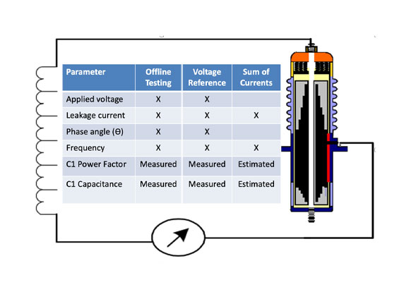
Based on physical measurements: Since replacement is costly, many utilities delay the related ‘cash out’ and decide instead to evaluate the condition of a bushing before replacing it. The following measurements are established methods to assess condition:
Dissipation Factor
Any increase in dissipation factor leads to higher dielectric losses of the bushing. Operating temperature of the bushing increases due to the increased losses, which then results in a further increased dissipation factor. In the long run, such a process leads to the thermal stability limit being exceeded and results in dielectric breakdown within the condenser core. The higher the rated voltage of a bushing, the more sensitive it becomes to any increase in dissipation factor value. Causes for an increased dissipation factor might include moisture ingress due to leakage; moisture ingress originating from the transformer oil; or ageing of the paper (mainly for OIP technology).
Extra caution has to be used when it comes to interpreting loss factor measurement results due to the fact that:
• dissipation factor rises exponentially at operating temperatures significantly higher than ambient (see Fig. 2);
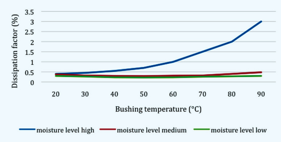
• dissipation factor should be measured close to the maximum permitted temperature of the particular insulation material so as to ensure thermal stability of the bushing under demanding operating conditions.
In particular, the second of the above requirements would suggest measurement be done at temperatures on the order of some 90°C as this would deliver the most informative value for assessing the condition of a bushing. Unfortunately, such a measurement is not always practical under typical site conditions. On the other hand, measurements at room temperature are often also insufficient since this and 50Hz alone are not sufficient to reliably detect increased humidity level in a bushing. Measurement over a broader frequency range would provide more information, e.g. by applying dielectric frequency response (DFR). Some correlation, however, can be found between a 50Hz measurement, high-temperature values of the dissipation factor and its low-frequency values at room temperature. Various methodologies have been proposed in this regard such as frequency domain spectroscopy (FDS) or time domain measurements (e.g. polarization depolarization current PDC). A combination of both would be more suitable to detect critical moisture content in the insulation using a measurement that is feasible within the shortest time possible.
It should be noted that bushing insulation materials not only differ from one manufacturer to the other but may also be different among various bushing styles offered by the same manufacturer. Generic tables with ‘typical’ frequency-dependent characteristics have limited value when it comes to making a decision strictly based on a frequency-dependent measurement alone. Yet when a similar measurement has been performed at the beginning of the life of the bushing (‘fingerprint’ measurement on site), then this type of measurement promises to provide a good basis for solid future bushing monitoring and assessment over its service life.
In the case of doubt, it is always advisable to contact the OEM and request evaluation support. Working together with reputable bushing suppliers with a long manufacturing and R&D history is a good choice when planning a bushing monitoring and assessment strategy. In view of the above, recommendations are:
• a ‘fingerprint’ measurement at a defined and recorded temperature, at different frequencies, is a must for being able to assess the condition of a bushing later on.
• temperature during subsequent measurements should be identical to that of the ‘fingerprint’ measurement. The thermal time constant of a large bushing can be very large, exceeding 48 hours, and sufficient time therefore has to be allowed for the temperature inside the whole condenser core to stabilize. If not possible, support of OEMs to interpret results is recommended since they have the model and tools necessary to correct for temperature effects.
• even though increased values of dissipation factor and C1/ C2 indicate increased moisture content with high probability, absence of such increases cannot guarantee that the condition of the bushing insulation material is good, especially if only 50Hz measurements are performed.
Dissipation Factor – Voltage Dependence
If possible, the dissipation factor should be measured over a broader voltage range, e.g. from 2 kV up to 12 kV. Should the loss factor not be constant with increasing voltage, this typically indicates faults in high-voltage or ground foil connections.
Capacitance
An increase in value is a hint that there is partial breakdown inside the condenser core. The field stress inside the bushing will then increase and may eventually result in a complete inner breakdown of condenser core insulation. Causes for inner breakdown might be:
• Overvoltages (lightning strikes, reactor switching operations, harmonics);
• Partial discharges;
• Contamination and bubbles remaining from production process;
• Deterioration of insulating material.
Dissolved Gas Analysis
DGA is only possible on OIP bushings and state-of-the-art OIP bushings are equipped with an oil release valve where a small oil sample can be taken. This measurement, however, must be applied with care since numerous bushing failures have been reported shortly after having taken a sample. One of the main reasons for this was that the gasket was reused instead of being replaced with a new one. This allowed moisture to penetrate into the bushing. Leakages are a major driver for bushing replacement and the need for an overhaul. If there is no oil release valve, the bushing needs to be opened to take an oil sample. This increases risk of leakage, if resealing of the bushing is not done properly. Furthermore, taking several oil samples will over time reduce the oil level inside the bushing.
Partial Discharges
Partial discharge occurs if there is a defect in the electrical insulation, such as voids, cracks or delamination and any of these can lead to degradation of the electrical insulation material. Bushings with solid insulation (i.e. RBP, RIP or RIS) tend to be more sensitive to partial discharges than OIP bushings that have liquid insulation. In a solid insulation material, partial discharges allow the defect to propagate through the insulation until there is a partial or full breakdown of the insulation. By contrast, in a bushing with liquid insulation convective flow of the oil caused by different oil temperatures helps to dislocate the defect within the bushing in a ‘self-healing’ process.
Visual Inspection
Whenever a bushing is assessed, visual inspection should also be performed.
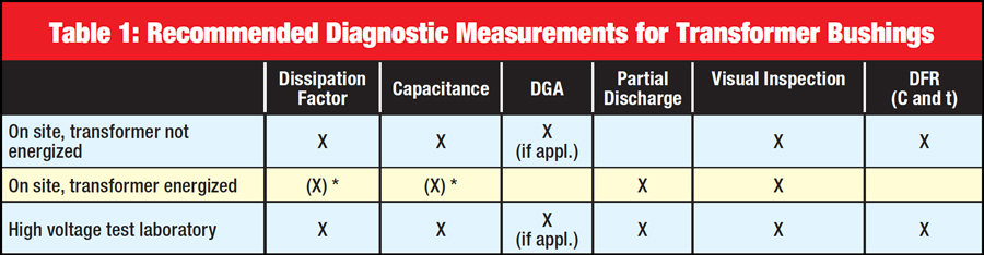
Table 1 provides an overview of these various diagnostic measurements recommended for transformer bushings. For proper interpretation of results, it is crucial that an initial fingerprint measurement be taken before a transformer is placed into service. The temperatures of the condenser core and test set-up have to be properly determined and recorded during such a ‘fingerprint’ measurement. Moreover, measurements at the time intervals recommended for any particular type of bushing are needed to determine the measurement trend as well as the speed of any ageing. Some utilities perform these measurements in a 5 year cycle, others more frequently. The proper intervals will depend on bushing type, age and the assessed impact of any premature failure.
Step 3: Definition of Bushing Style to Replace Installed Fleet
Utilities that have allowed many different types of bushings from various manufacturers to comprise their fleet require an increased number of spares that need to be kept for emergencies. This has a negative impact on net working capital and results in increased storage as well as re-stocking costs. Therefore, any replacement strategy for a bushing fleet should ideally include reduction in variety of different bushing types to address this. A further grouping within the cluster will help reduce variation in bushing types. It should also be noted that excessive stock keeping not only generates more costs but also increases the risk that improper storage will damage or even destroy a bushing. The new RIS bushing technology is easier to store and can therefore help reduce such costs. Criteria for grouping the cluster in an effort to reduce bushing variety might include:
• Voltage level
• Current level
• Similar dimensions
Experience has shown that ‘overrating’ bushings in an effort to fit more bushings into the same cluster and thereby reduce number of variations is often the less costly strategy. Small deviations in dimensions can often be compensated for by use of inexpensive adapters, e.g. compensating different current transformer extensions with an adapter that can be placed between the bushing and transformer turret.
Step 4: Set Up Risk-Based Replacement Schedule
The schedule for replacing a bushing should be based on the level of importance of the substation within the overall system. To properly quantify risk, it is not sufficient to only assess likelihood of a bushing failure but also the potential impact of resulting downtime. Measurements taken in Step 2 serve as the basis to predict the probability of a failure. To assess system impact, the following criteria might be considered:
• Importance of substation/power plant to the grid;
• Possible secondary damage in case of a failure/transformer fire;
• Risk faced by personnel inside and outside the power plant;
• Type of power plant/substation (e.g. GIS → VFT, pumped storage hydro power station → many load changes).
Step 5: Execution of Bushing Fleet Replacement Strategy
To replace a bushing, the transformer needs to be taken out of service. Such an outage is typically combined with transformer refurbishment to minimize resulting downtime. Typical transformer refurbishment involves measures to extend lifetime such as renewal of corrosion protection, re-sealing transformer, treatment of transformer oil, etc. The spare bushing should also be replaced at the same time to eliminate risk that an aged spare bushing will be unavailable in case of emergency.

Conclusions
A structured and holistic approach for replacing an aged fleet of bushings will reduce the risk of failures and associated transformer downtimes. Due to the fact that failed bushings (mainly OIP bushings) are one of the main causes of transformer fires, it is advisable to take special precaution in the case of aged bushings of this type. Some experts suggest using RIP bushings with silicone insulators to not only reduce risk of failure but also minimize any secondary damage in the unlikely event of failure. Furthermore, with clever design for replacement bushings, storage and restocking costs can be significantly reduced. Key recommendations are:
• Take fingerprint measurements of every bushing before the transformer is energized for the first time to determine the value of capacitance and dissipation factor. Measurements should be taken over a larger frequency range (e.g. with the DFR method) at a well-defined and recorded temperature;
• Perform electric measurements at regular intervals (depending on bushing technology) to track ageing of the bushing;
• A bushing fleet should actively be managed, following a holistic and comprehensive strategy to reduce failure risk, storage and restocking costs;
• Standardization of the bushing fleet to only a few different types is the preferred strategy;
• A fleet management database with all relevant data of installed bushings should be established;
• After 25 to 30 years’ service, replacement of the bushing fleet should be considered;
• Use of silicone outdoor insulators reduces likelihood and also the impact of a failure;
• OIP, RIP and RIS-type bushings should be free of partial discharges during factory acceptance test to ensure a slower ageing process of the condenser core insulation. PD extinction voltage larger than twice the maximum phase-to-ground service voltage is recommended for dry type bushings;
• RIP and RIS type bushings are recommended whenever collateral damage, in event of bushing failure, is a special concern;
• RIS technology is recommended whenever storage and operation in high humidity climates is an issue.