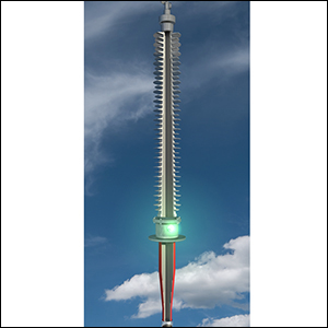
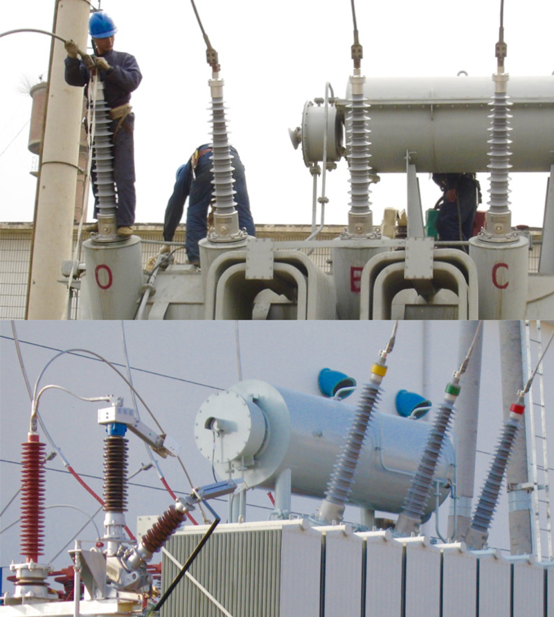
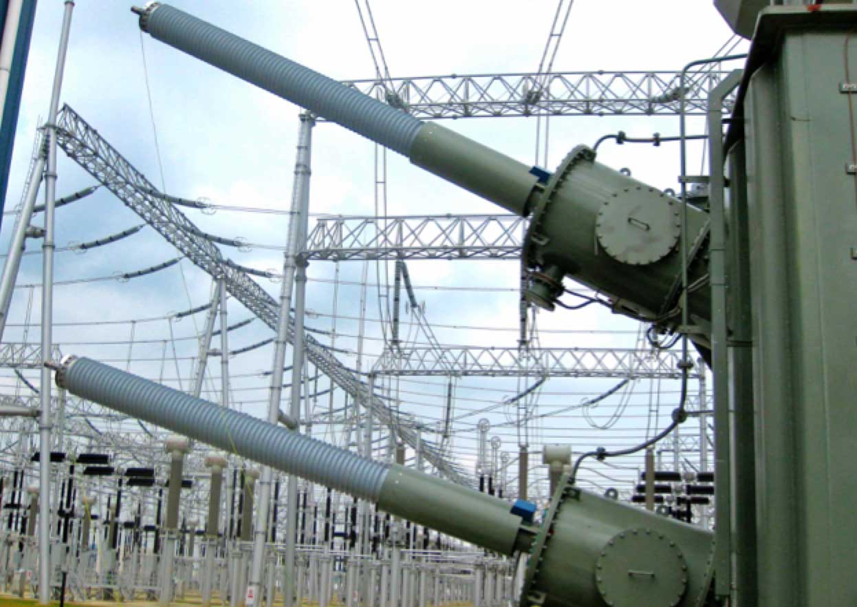
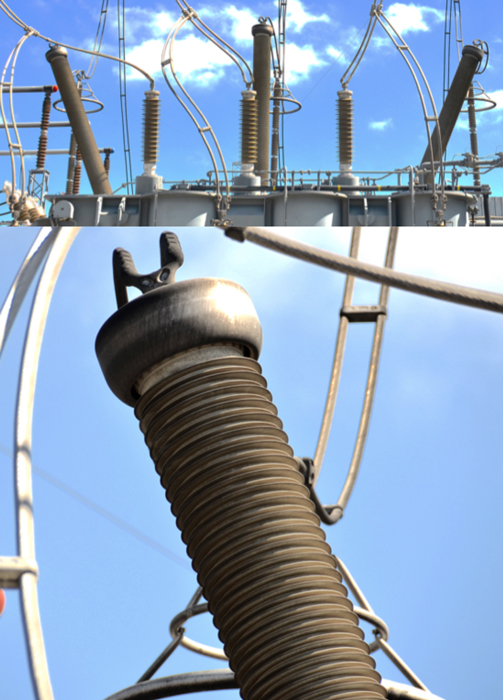
Bushings are devices that allow conductors to pass through the earthed walls of transformers, switchgear and substation structures. An integral part of this function involves meeting all the electrical, thermal and mechanical requirements of the application. For example, bushings must provide reliable electrical insulation both internally (against breakdown) and externally (against flashover) of the conductor exposed to the rated voltage and also to periodic service overvoltages – even under contaminated conditions. Another key requirement is providing the mechanical strength needed to support the conductor as well as all external connections, including under short circuit and possible seismic forces. Moreover, a bushing must have the proper thermal design to avoid overheating of any of its components and prevent onset of ageing phenomena in its insulation – both at rated current and during short circuit events.
This past overview combined an edited contribution by retired Prof. Stanislaw Gubanski of Chalmers University of Technology in Sweden with excerpts from past issues of INMR.

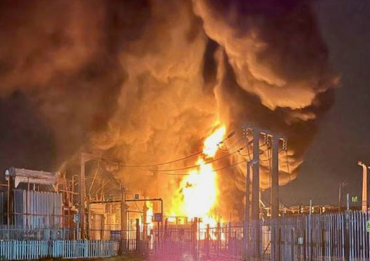
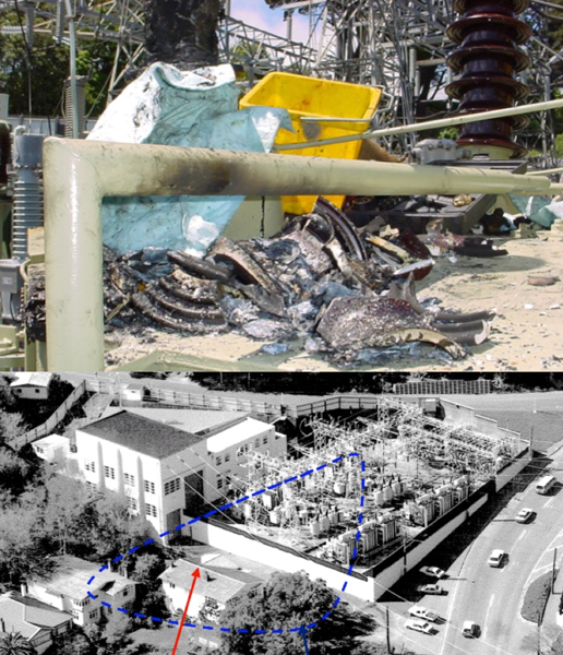
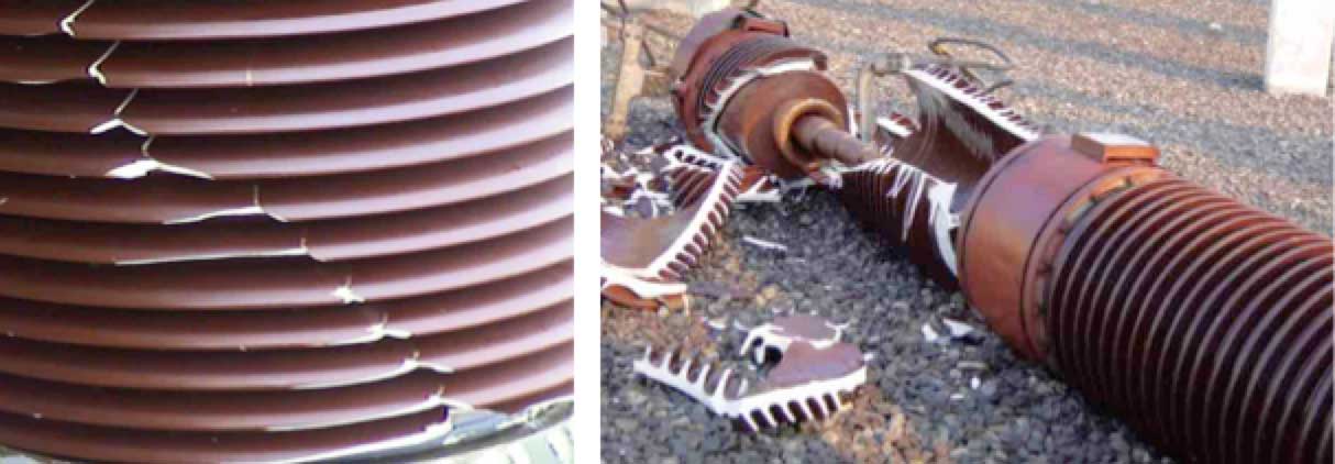
Like a surge arrester, a bushing is a relatively low cost component ensuring the safe operation of a high value asset. While bushings account for only about 5% of the cost of a power transformer, their catastrophic failure can lead to total loss of the transformer and possibly other expensive equipment as well. Certain types of bushings can threaten not only substation personnel but even nearby communities.
In their early years, bushings were little more than hollow porcelains filled with transformer oil or solid resin surrounding the conductor. Such simple bulk and solid type bushings are in fact still being applied at medium voltage levels. But as networks have become more sophisticated, the need was recognized to better distribute the electric field generated across a bushing – especially at higher voltages. This resulted in designs that were capacitance-graded. The basic principle was to distribute the natural field between conductor and earthed flange by employing intermediate conductive layers radially (to lower the field at the conductor and better utilize the insulation material) and also axially (to allow for higher flashover voltage values for a given arcing distance).
Originally, materials used in the cylinders wound around the conductor included resin-bonded paper and carbon materials. These were later modified to designs involving less conductive grades of paper along with aluminum foil. One of the motivations behind development of field-graded bushings was reducing the diameters required for the porcelain housings. On ungraded bushings, electric field tends to be concentrated around the flanges and therefore risk of breakdown becomes high. On fine-graded bushings, stress is linearized and spread over more distance, resulting in greater safety margin. For example, the porcelain housing diameter on a simple 110 kV field-graded bushing is about 240 mm measured across the sheds. But to handle the same stress, an identical ungraded bushing would need a housing of almost double that diameter. The benefits of narrower external diameter translate into lower cost for the housing, reduced weight, less oil and less clearance diameter of the embedded shielding in the lower part.
The basic principle in bushing design consists of a conductor surrounded by an insulating solid cylinder that is mechanically fixed to the earthed barrier. As discussed, distribution of electric field inside such a construction, is highly non-uniform in terms of both axial and radial components. The highest stress concentration appears at the so-called ‘triple junction’ between the earthed wall, the insulating cylinder and the gaseous or liquid medium outside the bushing body. This localized high concentration of stress can trigger the onset of partial discharges, sometimes referred to as ‘gliding discharges’ since they have a strong capacitive coupling to the bushing’s internal conductor and therefore proceed along the insulating cylinder’s surface. They can lead to tracking along the bushing and even result in flashover. Initiation of gliding discharges as well as their subsequent development becomes easier when the unit capacitance of the insulation (i.e. across its thickness) is greater. Therefore, the voltage level for their ignition and propagation (virtually equal to flashover voltage) is determined by this parameter. This stands in contrast to other types of discharges, where the typical controlling parameter is electrode separation distance.
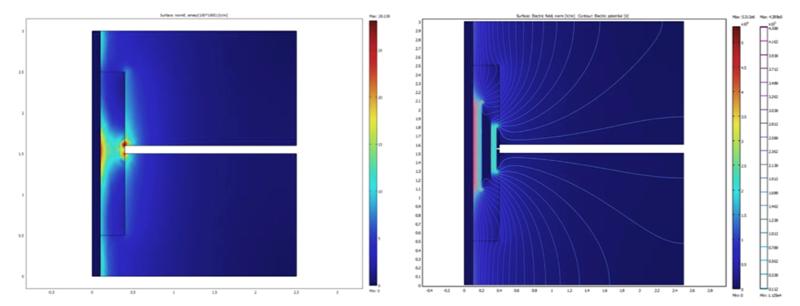
Given these considerations, the best way to increase a bushing’s flashover withstand voltage is by improving electric field distribution along its surface. In the case of higher voltages, the most effective means to achieve this is through capacitive control for AC applications and resistive control for DC applications. Capacitive control is based on inserting metallic screens into the solid insulation of the bushing, essentially forming a system of in-series connected capacitors whose magnitude depends on geometric arrangement. Perhaps the most frequently used and effective solution is when series capacitances are maintained at equal levels. Fig. 1 illustrates the impact of modifying field distribution this way.
Inserting metallic screens during manufacture of a bushing used to be demanding and labor-intensive but modern core winding equipment has made it highly automated. In the case of paper insulated bushings, metallic foils are inserted between the different paper layers. Choosing the appropriate radius and length of these screens allows for the desired series capacitance. Optimal resistive control of electric field distribution in the case of DC bushings usually involves covering the critical region near the electrode with semi-conducting layers. The aim here is to increase resistance with increasing distance from the earthed electrode.

Alternative Bushing Technologies
In the case of bushings for higher system voltages, there have traditionally been three main types of insulation system used: oil-impregnated paper (OIP), resin bonded paper (RBP) and resin-impregnated paper (RIP). New resin-impregnated synthetic (RIS) types, without oil, have also been developed and are finding growing application.
OIP Bushings
Since the main insulation of substation transformers has been based on oil-impregnated paper, this same insulation philosophy has carried over and become the most commonly used technology for constructing bushings. In fact, it is estimated that up to two-thirds or more of all installations of a bushing on a power transformer involve an OIP design. In certain markets, such as China and the United States, this proportion is probably even higher. This market preference for OIP style bushings has been maintained over the years due to a variety of refinements made by some of the leading manufacturers. These improvements have allowed the technology to remain attractive both to intermediate bushing customers (i.e. transformer OEMs) and also to final users, in spite of changing needs and requirements. For example, some bushing suppliers offer standardized high creepage porcelains on all OIP bushings they sell. The goal was to allow the same bushing design to be used across a variety of service environments and thereby reduce the need for end users to stock many styles of replacement units. It has allowed bushing manufacturers to streamline their own ordering and inventorying of porcelain to reduce unit cost as well as production lead times.
Similarly, over the years OIP bushing suppliers have made design changes aimed at reducing the diameters of porcelain housings to make them slimmer and lighter. This has suited transformer manufacturers who prefer bushings that are easier to handle during transport and installation. Slimmer profiles have offered benefits apart from reduced weight: firstly, the porcelains themselves carry lower cost since decreased diameter significantly reduces purchase price; secondly, slimmer designs mean the volume of oil within bushings could be correspondingly reduced. With this has come progressively less concern about risk of leaks and fires.
Apart from these types of design changes on an industry-wide basis, various individual OIP bushing suppliers have made additional improvements: better methods to seal against leaks; designs to facilitate horizontal or vertical mounting; better visual monitoring of oil levels; easier interchangeability between transformer and switchgear applications; and better mechanical contacts between top terminal and conductor to avoid the potential for heating should the conventional threaded contact weaken. Other refinements have also been developed that allow OIP bushings to be changed out quickly in the field with minimal impact on operation of affected apparatus. Due to competitive forces, these innovations have been matched by others in the industry with the result that most suppliers offer improved versions of OIP technology.
One of the areas within this technology where there could be growing interest for further development is improved condition monitoring. There are hundreds of thousands if not millions of OIP units operating worldwide and one question is how intelligent such a design should be, especially in regard to internal monitoring of oil level and other service parameters. Still, given the many refinements made to these designs over the years, it seems unlikely more can be done to enhance performance and functionality or further reduce cost. Indeed, this style of bushing has reached a state of design maturity with limited room for further optimization.
Resin Bonded Paper (RBP) Bushings
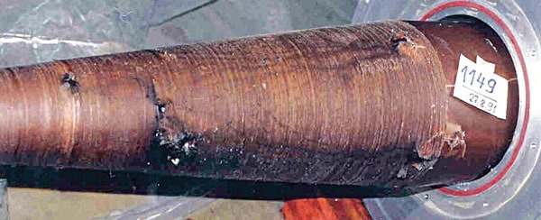
Manufacturing RBP bushings has been based on winding layers of resin-coated paper around the conductor under heat and pressure to laminate the layers together. This process is inherently difficult to control and therefore such designs have suffered relatively large numbers of failures over the years due to voids and other defects. In spite of this drawback, however, the RBP bushing style has found a market because of price. Presently, use is limited mainly to lower voltage levels since risk of thermal instability and even runaway due to dielectric losses in the paper is comparatively high. For this same reason, operating radial stress in such designs is usually maintained at around 2 kV/mm, lower than for other bushing types.

Resin-Impregnated Paper Bushings
Compared with RBP bushings, significant improvements have been achieved by introducing a technology whereby the paper insulation is impregnated with epoxy resin and then cured. The resulting insulation system, containing field grading elements, is dry and void free. This technology involves higher material as well as product costs but offers benefits such as being non-combustible, providing an impregnable seal for the transformer tank, being easily machined to required dimensions and remaining unaffected by ambient humidity. Moreover, when equipped with a composite housing, there is no risk of explosive shattering. Great care, however, has to be taken during the curing cycle to avoid internal stresses and formation of cracks – especially as volumes of material increase for high voltages. Typical radial operating stress in RIP bushings is around 3 kV/mm.
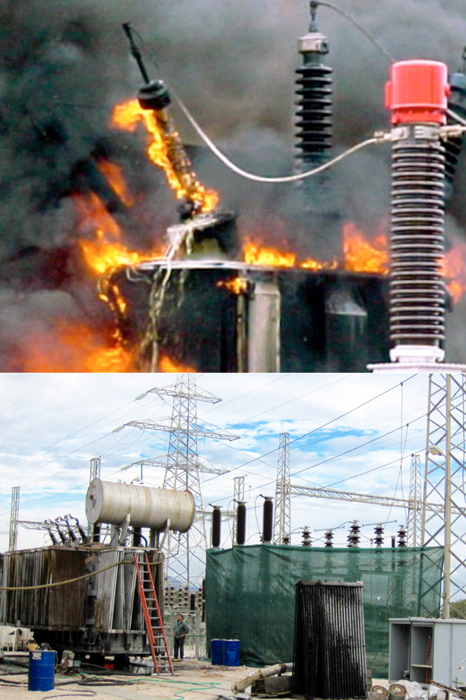
RIP bushings have no dynamic processes occurring within their cores and therefore offer long service lives. Other advantages include eliminating any risk of leaks or explosive failure of an oil-filled component. Over the years, incidents of exploded OIP bushings resulted from excessive operating temperatures when cooling systems failed on transformers operating at 100% load. Even if not leading to an explosion, situations such as this can still shorten the effective service life of an OIP bushing to as little as 10 years. While a normal OIP bushing can operate well up to 105°C, an RIP style can deal with temperatures greater than 120°C. Indeed, testing by suppliers has confirmed that thermal ratings for RIP bushings are considerably higher than for OIP equivalents. This superior thermal behaviour is an advantage in utility markets where transformers are being run at high load.
Apart from thermal advantages, RIP bushing technology is viewed as the way forward simply because it offers a dry solution. In spite of successive refinements made to OIP designs, their most important drawback remains because it revolves around the presence of oil. Typical problems have included leaks due to worn out seals, excessive filling of reservoirs in horizontal mount applications or unusually high operating temperatures. These types of bushings also suffer from greater vulnerability to lightning strike or other factors that can trigger explosive failure. Similarly, moisture ingress presents a constant and potentially severe problem. Finally, in the case of connection to SF6, presence of oil is undesirable due to the consequences of leaks. All these drawbacks favour a dry bushing technology such as RIP. Indeed, there seems an accumulating trend toward dry bushings that is reflected in a steady rise in its share of the total graded bushings business. Further increases are expected due to application-specific advantages of RIP technology. For example, the OIP design for oil-to-gas connections is cumbersome and difficult to maintain while the RIP alternative is a comparatively easy technical solution. RIP technology also offers important advantages in the area of oil-to-gas and oil-to-oil applications.
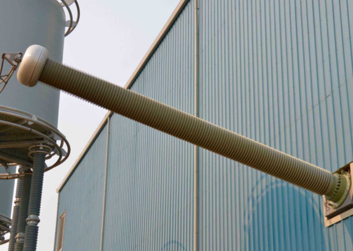
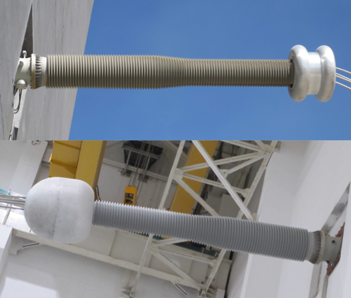
As with OIP technology, suppliers of RIP bushings have sought to incorporate product refinements to justify the higher price normally associated with this technology. Among the most important developments in this regard has been application of silicone housings in place of the porcelain that still dominates OIP bushing installations. This technical solution is viewed as the ultimate in bushing design and performance. There is no doubt that market acceptance of silicone housings on a bushing has been far greater for RIP than for OIP designs to the extent that probably more than 90 per cent of all graded bushings that are silicone-housed have RIP cores. This is because the real advantages of silicone material are most evident to customers when applied to this technology and in some respects even help RIP better compete against OIP styles. Germany, Switzerland and Austria are examples of markets where dry bushing technology incorporating silicone housings is widely accepted due to safety and environmental concerns.
The motivation behind transition to silicone in place of porcelain as a housing for bushings has involved factors such as reduced risk to people and apparatus, better pollution performance, easier handling and faster production lead times. Bushings can be especially sensitive to pollution since they are often inclined or located under roofs – situations that can lead to uneven deposition of contaminants. A bushing then becomes more vulnerable to flashover and in such cases silicone is preferred to porcelain. Other application conditions can also make a bushing more vulnerable to pollution and favour a silicone housing over one made of porcelain. However, one of the challenges in replacing porcelain with silicone on an RIP bushing has been cost, especially at voltages below 245 kV where much of the volume is focused.
Slimmer diameters of RIP units compared to most OIP designs have also meant that the porcelain shells being replaced are less costly, only accentuating the price difference. An early problem when it came to changeover of external insulation away from porcelain was that the new silicone insulators were often specified as a one-for-one replacement for porcelain. This meant that the larger flanges required for porcelain were also specified for the composite alternative, even though not strictly necessary. This has become less an issue since bushing suppliers and users have both grown to understand the need to optimize the entire design. Moreover, the growing level of standardization in this industry has resulted in sizes and diameters of fittings becoming more uniform.
Among the notable developments when it comes to application of silicone housings to dry bushings – both RIP & RIS styles – has been a process that sees sheds molded directly onto the cured core. This technology has been available for many years and is best suited up to a maximum voltage. The principal advantage is cost reduction because direct molding eliminates need for the FRP tube as well as the dielectric material that fills the space between core and tube. Notwithstanding cost advantages, application of direct molding onto RIP cores has not achieved widespread use. Apart from the investment needed by the bushing manufacturer to be able to implement this process in-house, there are technical issues, especially at higher voltages. For example, there must be an extremely good chemical bond between core and silicone to avoid any possibility of interface problems. There is also the issue of ‘cold switch-on behavior’. When silicone rubber has been molded directly onto the RIP core, vapor will likely have migrated through the material before energization and could be absorbed by the resin body. This could mean that, at least initially, the bushing will have a higher dissipation factor.
Another potential drawback of direct molding relates to mechanical function. If the mechanical requirements of the bushing exceed those of its RIP core and conductor, the added mechanical strength of a tube will be necessary to help carry the load. A tube also offers the benefit of providing a barrier against moisture. In this regard, it may not be appropriate to draw a parallel between mold-on silicone bushings and experience with polymeric arresters that have experienced growing use of direct mold technology. Arresters are not intended to last 30 to 50 years and, if they fail, it is often not a serious problem. If a bushing fails, the whole transformer is in trouble.
Apart from external insulation, there do not appear any major developments in the way RIP cores are produced that might significantly reduce cost. Drying and curing cycles are critical steps and cannot easily be shortened. Nor has the resin that forms the body of the RIP bushing changed significantly. Indeed, rather than looking at changes in the resin body itself, suppliers have typically looked for optimized production logistics. The entire process for manufacturing these bushings is technically demanding, particularly as voltage levels climb, and this has limited the number of qualified suppliers. Whatever practical refinements are still to be made to RIP bushing technology will likely be in such areas as better grading of the condenser layers to make them progressively smaller and more efficient. There may also be improved process control to improve robustness of manufacturing, making it a more repeatable process that results in a consistent product every time. A void the size of a pin hole can result in an entire RIP core being relegated to the scrap heap. There is no possibility to recycle the material since it is a thermoset resin that cannot subsequently be melted down.
In the end, a purely technical comparison between OIP and RIP bushing technologies may not be the decisive factor in customer preference. Given the role of commercial considerations in purchase decisions, success will go to bushing suppliers who offer the most features for the price, irrespective of technology. These include creepage distance, seismic capability, cantilever strength and total interchangeability for application on transformers or breakers, among others. Similarly, not everyone in the industry is convinced that RIP is always the better choice. This technology comes with disadvantages that must also be considered – from higher price to greater uncertainty about how the core is ageing. This is because, unlike the case for OIP styles, reliable ageing analysis on an RIP bushing cannot be performed in the field. Rather, the unit has to be removed from service and returned to a laboratory for testing. Given the power utility environment, there will always be concerns about how bushings are ageing. For this reason, some predict that the tendency for new bushing types may be more oriented toward gas-filled or gas-impregnated units in place of those relying on organic dielectrics.
Other Designs & Considerations
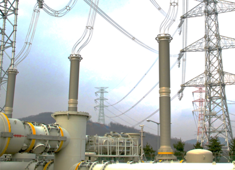
In contrast to longstanding OIP, RBP and RIP bushing technologies, more and more designs today make use of pressurized gas, predominantly SF6, as internal insulation. Metallic screens are used for controlling electric field stress inside the bushing body. As discussed, selection of the external housing of the main insulation in a bushing is one of the key factors affecting service performance and cost. For indoor applications with low contamination and normal humidity, resin-based RIP solutions do not require an additional housing over the epoxy core. This is not the case, however, for either OIP or gas-filled bushings, both of which require porcelain shells or composite insulators. For safety considerations, application of the composite solution is often preferred when considering a gas-insulated unit under high internal pressure.
Another way to categorize bushing technologies available today relates not to commonalities in design and construction but rather to main areas of application or applicable voltage levels. Probably the most common application of bushings is on power transformers, where the outer parts operate in air, other gas or oil. OIP bushings are currently available up to 1200 kV while capacitance-graded bushings with epoxy resin impregnated insulation have been developed up to 1000 kV. Apart from UHV, another specialty application includes high current bushings (i.e. with operating currents up to 40 kA) used on the low voltage side of transformers and also in generators. One of the key design requirements here is capability to effectively dissipate heat.
Another broad group of bushing applications involves connections to gas-insulated switchgear (GIS), most typically as entrance bushings. RIP based condenser cores embedded inside a porcelain housing or composite tubes with silicone sheds both function well in this regard. For the gas part, a discharge resistant surface varnish is necessary to fulfill the requirement of resisting corrosive by-products from decomposition of SF6. In addition, requirements for direct connection between transformer and GIS are becoming increasingly common and special designs of oil-to-gas bushings have been developed for this purpose.
Yet another growing application – especially in countries such as China, India, Brazil, South Africa, Norway and Canada, among others – relates to HVDC converter stations. Nowadays, manufacturers offer special bushings for connecting to HVDC transformers, reactors or air-insulated system components up to ± 800 kV DC and higher. These can operate in a transformer oil environment, indoors or for any outdoor connections. As discussed, in contrast to high voltage AC applications, the performance of an HVDC bushing is influenced by the resistive properties of its materials and therefore stress control must be appropriately adjusted. For example, it is important to control the field in the oil part of an OIP HVDC bushing since the ratio between resistivity of paper and that of oil can be as high as 104. Use of composite insulators in the design of bushing shells for the highest voltage levels provides not only superior flashover performance but also high mechanical withstand. Another issue relates to the dynamics of charging under DC. This remains an important factor to take into account – not only during testing but also in terms of impact on flashover performance, especially during voltage reversals. Yet another factor to consider in UHV bushing applications relates to better understanding ageing of polymeric materials in such an environment.
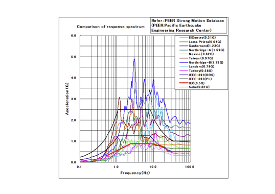
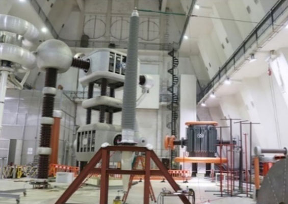
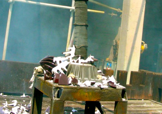
The tendency towards increased transmission voltage levels and the resulting growth in dimensions of bushings has also made it necessary to better control parameters such as seismic behavior. Historically, several methods have been used to verify seismic capabilities of bushings. These involve static calculations to estimate the forces generated during a seismic event with a given ground acceleration and then comparing this against design capabilities of the equipment. Although IEEE and IEC standards involving shake tables have been used to qualify equipment for seismic areas, past earthquakes indicate that transformers and bushings that passed these tests can still sustain significant damage. To overcome this deficiency, numerical simulations have been developed and refined.

Conclusions
Development in bushing technologies has been impressive if not always obvious. Bushings today might look much like those of the past but there have been subtle refinements and improvements in scale, functionality, performance and cost. Among the driving forces behind this progress have been ongoing efforts by the industry to reduce costs as well as production lead times and standardize bushings to reduce need for users to stock many different types of spares. Moreover, internal competition between OIP and RIP styles has also pushed suppliers to seek optimization in both designs.
Another driver in development of bushing technology, especially in recent years, has included growing use of HVDC based transmission as well as increases in UHV AC voltage levels. At the same time, environmental demands for developing oil-free as well as low or SF6-free high voltage substations are creating new design challenges for the industry. Today, manufacturers have developed and already offer bushings for voltage levels exceeding 1000 kV and for high rated currents. On the HVDC side, work on developing ±1000 kV bushings has progressed.
RIP bushing technology seems well understood and this allows production of partial discharge-free condenser bodies, even for extremely large units. Increased use of new gas compositions (e.g. N2/SF6) in GIL will require elaborating new design criteria. Finally, growing application of silicone housings in bushing designs has created the need to further study their long-term behavior – especially under combined DC voltage, thermal and mechanical stresses.
____________
RELATED ARTICLES:
Evaluating Reliability of Bushings
Test Requirements for HV Bushings
RIS Bushing Technology: Reliability Testing & Field Experience