Composite insulators have offered solutions in specific areas where ceramic insulators have not proven ideal. One such application is as interphase spacers to prevent conductor galloping. In this case, composite spacers serve to improve the aerodynamic or ‘aeroelastic’ behavior of lines exposed to challenging climatic effects such as wind and especially combinations of wind with deposits of ice or sleet. These interactions have the potential to produce harmful stresses on different parts of the line through induced motion and conductor vibration – stresses that can cause extensive damage and also endanger line performance. This edited article, extracted from a past INMR WORLD CONGRESS paper, examined conductor galloping and application of composite interphase spacers to control it. Knowledge and data presented was developed from a full-scale test line set-up in a mountainous area of Japan.

Because of complex physics and the highly unpredictable way conductor motions and vibrations can develop over time, it is often impossible to predict and deal with all potential future galloping problems during the design stage of an overhead line.
Finding the best solution when such problems arise first requires evaluating service experience to gain insight into all factors that influence onset of destructive stresses and vibrations on a line. This way, there is the greatest chance of finding the most effective measures to keep these within allowable limits. Interphase spacers are among the control devices available to engineers to prevent the most dangerous kinds of vibrations, such as those caused by ‘sleet jump’. But to understand how these devices can help and to better assess their effectiveness, it is necessary to review some important principles.

Development of Vibrations Along Transmission Lines
Even though transmission lines have a highly flexible form and relatively slender profile, they are continuously exposed to the forces of climate and wind. This makes them susceptible to development of sustained, cyclic conductor motions or vibrations. The specific type of vibration depends on several factors and can take different forms:
1. Aeolian Vibrations
These are caused by alternating wind forces and impart an oscillating lifting force to the conductor. This type of vibration is characterized by frequencies in the range from 5 to 100 Hz, with amplitudes of only a few mm up to the full diameter of the conductor. The phenomenon is dangerous, because fatigue-bending stress can occur at or near conductor fixation points such as clamps and cause breakage of individual strands. It is common to use special dampers (e.g. the Stockbridge damper) to minimize the level of such vibrations.
2. Wake-Induced Oscillations
Such oscillations are typical only for bundle conductors for which some sub-conductors are in the wake induced by those to the windward side. The latter then provide a shielding effect on their leeward counterparts. Four types of such wake-induced motion can be distinguished: sub-span mode (in a section between two spacers of the bundle); vertical galloping; horizontal galloping; and rolling. Basically, the oscillation is produced by the wake, which induces lower drag coefficients and creates lifting forces on leeward sub-conductors. Due to this kind of aerodynamic instability, the leeward conductor starts to move and, because of conductor spacers inside the bundle, the windward conductor is forced to participate in the movement. While this kind of vibration does not usually lead to a pronounced reduction in phase-to-phase distances, a portion of the wind’s mechanical power is absorbed by the conductors and can cause fatigue, especially if repeated over long periods of time.
3. Galloping
Conductor galloping (also referred to as dancing) is a phenomenon where transmission line conductors vibrate with large amplitudes. This produces violent dynamic stresses in the conductors that can lead to damaged insulator strings and tower structures. Under certain conditions, conductors having different potential can come into contact or dangerously approach one another such that a short circuit occurs. Preventing this phenomenon is therefore of fundamental importance in maintaining reliable service of the line.
Interaction of Iced Conductors & Wind
One of the most common ways galloping develops is as a result of interaction between a steady, moderately strong crosswind that acts on an asymmetrically iced conductor surface. Through this type of ‘self-excitation’ process, periodic, high amplitude vibrations (or oscillations) can occur on either single or bundle type conductors.
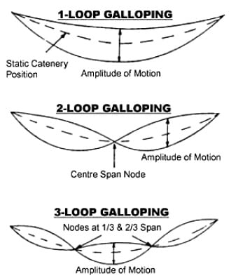
The amplitudes can approach the value of the sag and have motion mainly in the vertical plane, with frequencies of between 0.15 and 1 Hz depending on line design and specific mode of excitation. This form of conductor galloping can affect several neighboring spans and last a few minutes or much longer. Most of the observed galloping in this case takes the form of standing waves that occur with one, two or sometimes as many as 10 loops in a span (although galloping events with three or less waves per span are most common). In the case of more than three loops, the galloping generally has smaller amplitudes. When this problem develops, the oscillating motions of the phase conductor and overhead ground wire can lead to contact. Alternatively, the critical air gap breakdown distance between conductors of different phases or between the phase conductor and ground wire can be reduced. This will result in short-circuit and operation of the relevant circuit breakers to switch-off the line.
In the case of automatic reclosing, switch-on will be successful. However, contact or approach of the conductors will quickly re-occur because of the periodicity of the galloping phenomenon. The repetitive short circuit can then damage the conductors through the high energy, high temperature power arcs that develop between the conductors as they approach too close to one another or come into contact. The negative mechanical effects have to be considered as well (as mentioned above).
One of the main processes contributing to galloping is formation of an ice coating on the conductor. Since a conductor’s surface is not perfectly smooth, some snow adheres to it and marks the onset of ice deposit formation. From that stage on, the torsional rigidity of the conductor (or conductor bundle) becomes important. The rotating (or twisting) torque that develops as ice forms causes the conductor to turn and the snow deposit gradually increases to the point that a complete sleeve has been created around the conductor.
A secondary problem – known as ‘sleet jumping’ – is caused by the large ice deposit that has formed. This is because when conductors become covered by ice there is a tendency that the conductor closest to the ground will shed its ice first. Upon unloading, this lower conductor can jump toward the upper conductor, possibly leading to a temporary short circuit. Once the lower conductor has recovered from its initial ‘ice jump’, it often settles into a new position with less sag than before and this can persist for a long period of time. If the upper conductor has still not shed its ice load, the reduced separation distance between the two can result in air gap breakdown between the phases. These examples serve to illustrate the complexity of the problem and that predicting the exact dynamic behavior of a transmission line can prove challenging. Studying it can therefore best be done only under real service conditions or alternatively using special test lines located in areas that exactly duplicate all relevant climatic conditions. Fortunately, simulation tools are available to track development of the conductor galloping process and some even take into account whatever control devices have been put in place to prevent or reduce the problem. However, these simulations need to be validated by continually analyzing actual phenomena and parameters obtained from real service conditions in the field.

Controlling & Preventing Galloping
Because of the dangerous effects of galloping, several alternative approaches have been used to avoid or at least reduce the problem. These include:
• Changing Line Routing or Design
Fully eliminating the potential for galloping is often impossible without high incremental costs in line design or construction. For example, the route of the line can be changed to areas where ice deposition becomes far less likely. Similarly, conductor cross-section can be increased as can clearance between conductors.
• Application of Damper/De-tuners
These devices are based on the fact that torsional (or twisting) movement of a bundle conductor arrangement and its vertical motion (because of lifting forces) interact with one another. The instability that causes galloping is enhanced when the frequencies of these two motions are close to each other (i.e. there is synchronization / resonance). The solution is therefore to separate the frequencies through some form of external intervention – a solution such as offered by so-called ‘pendulum de-tuners’. The de-tuning pendulum increases torsional frequency but is not able to dampen the torsion. One such anti-galloping device with promising results on e.g. twin horizontal bundle test lines is the Torsional Damper and De-tuner (TDD), which combines a de-tuning effect with high torsional damping.
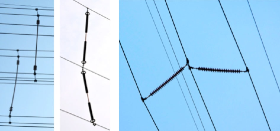
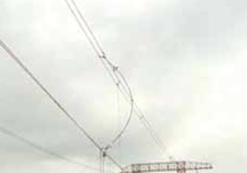
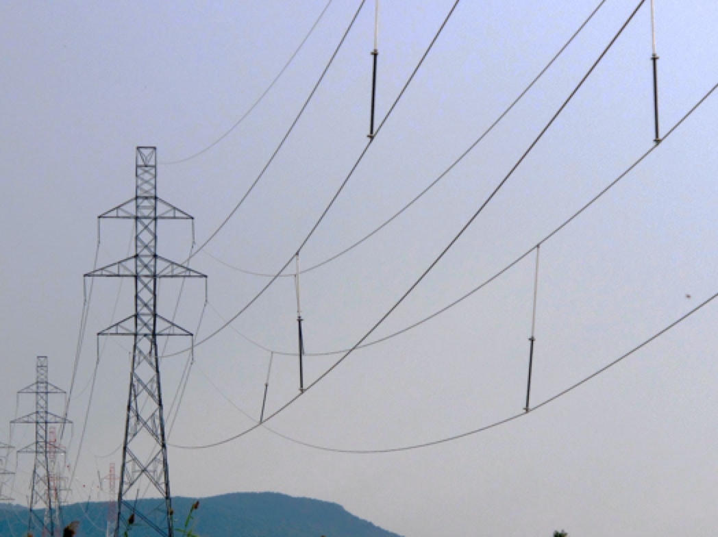
• Interphase Spacers
The main concept behind the application of interphase spacers is to prevent the most dangerous consequence from conductor galloping, namely phase-to-phase short-circuits. Attaining this is relatively straightforward and involves providing in-span mechanical couplings between phases, thereby maintaining phase-to-phase clearances at some pre-determined, acceptable limit. Moreover, from the oscillation damping point of view, these devices provide further benefit by limiting any torsional (twisting) motion of conductors or conductor bundles. Such control (damping) is achieved since the flexible composite insulators act to increase the conductor’s torsional stiffness. This type of arrangement offers other advantages as well that arise from the flexibility of the composite spacer. Should conductor vibration act to reduce phase-to-phase clearance, the spacer’s inherent resilience can absorb its energy.
Indeed, in several practical applications phase spacers are even placed to connect all three-phase conductors (conductor bundles), resulting in a several times over cross-connected system of sub-spans. This serves to greatly enhance the dynamics of the original system. For example, it could happen that not all phases are unstable when one or two phases are galloping. However, the connections through the spacers between the stable and unstable phase(s) provide the latter with additional aerodynamic and mechanical damping.
Interphase Spacers as Anti-Galloping Devices
General Set-up of Interphase Spacers
As discussed, perhaps the most serious consequence of large amplitude galloping is electrical failure caused by contact or critical approach of conductors with different potentials. To avoid this, it is logical to mechanically fix the clearance between the conductors inside the span utilizing insulating structures. While this solution has been applied in the past using ceramic insulators, their weight has created problems because of the modification needed to the pre-adjusted sag and stress of conductors, especially in the case of lower voltage transmission lines. Their installation and periodic servicing have also proven to be comparatively difficult. For these reasons, this kind of application is virtually completely covered these days by composite insulators. In fact, starting in the late 1980s and early 1990s, installation of composite interphase spacers accelerated rapidly and a CIGRÉ survey at the time reported that the majority of responding power supply companies used interphase spacers with polymeric insulators due to their low weight and high flexibility under compression loading.
Electrical Design of Interphase Spacers
When it comes to electrical design, the requirements and test methods for interphase spacers are similar to those of normal suspension or tension insulators. Key design parameters include:
• Power frequency voltage distribution along the unit and flashover under contamination;
• Switching impulse flashover voltage across conductor-to-conductor gaps;
• Lightning impulse flashover voltage.
The power frequency electric stresses across an interphase spacer are about 73% higher than for phase-to-ground insulation because spacers are subjected to line-to-line voltage. Stress release grading rings must therefore be applied at both ends for voltages of 154 kV and higher.
The electric field distribution of phase spacers is different from that of typical suspension insulators in that the spacer’s field is symmetrical. The field closer to the end fittings is also higher than for suspension units. Regarding pollution performance, because of the excellent surface hydrophobicity of silicone, no problems should be expected for composite phase spacers equipped with housings made from this material. For example, outdoor weathering trials were conducted years ago with such spacers at a test site in Japan, where they were exposed to continuous contamination by salt wind as well as frequent typhoons. In spite of the heavy coastal pollution and wind loads, no evidence of erosion or other deterioration was found after several years’ service.
Taking into account that typical applications for such spacers are in areas with cold climates, tests must also be made to evaluate spacer performance under accretion of ice and snow. Typically, such tests have confirmed that the insulator portion of a composite interphase spacer properly designed for heavy pollution will be able to withstand these high service stresses as well.

Mechanical Design of Interphase Spacers
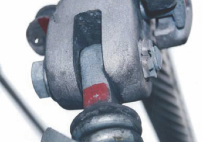
The mechanical stresses on an interphase spacer through galloping and ‘sleet jump’ include tension, bending (buckling) and fatigue caused by oscillation. The requirements for tension strength are not special but still have to be taken into account in the design of suitable hardware such as end fittings, clamps, etc. In this regard, tensile tests must be carried out on the complete arrangement. For example, the requested mechanical strength of a 275 kV interphase spacer used for 4-bundle conductor of ACSR 410 can be about 79 kN – a level which will easily be met by any well designed unit.
Far more important when it comes to mechanical stress, however, is a spacer’s bending/buckling behavior. In this respect, one of the principal merits of composite insulators as interphase spacers is that the onset of buckling or a certain amount of deflection at bending presents no danger so long as the stress remains below the critical limit at which deterioration starts. To provide some indication of such stress levels, relevant figures for allowable bending stress by utilities in Japan are as generally follows:
1. allowable stress: 294 MPa;
2. proposed range of maximum design cantilever load: circa 450-500 MPa.
To put these limits into perspective, it should be noted that the normal breaking stress of a good quality glass fiber-reinforced epoxy (FRP) rod is usually more than 800 MPa.
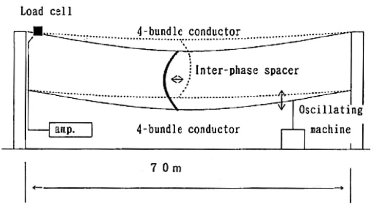
Frequent galloping/vibration can produce fatigue in interphase
spacers, especially in their metallic end fittings and connections, with risk of wearing out movable parts. Therefore, it is necessary to test their design and performance by simulating the galloping oscillation during a relevant large-scale test, which can be conducted with typical parameters such as:
Frequency of oscillation: approx. 1Hz
Amplitude of oscillation: 10 to 20 cm
Number of oscillations: 106 cycles
Such a test is deemed passed when there are no visible changes in the structure or in parts such as conductor clamps.
A further important design feature that must be tested is the ability of the interphase spacer to withstand the stresses when heavy ice/snow loads on the conductor (bundle) in the lower position suddenly drop. In this situation, the lower conductor suddenly jumps upward even as the conductor (bundle) in the upper position remains loaded. An interphase spacer located between the two will therefore be subjected to great compression stress.
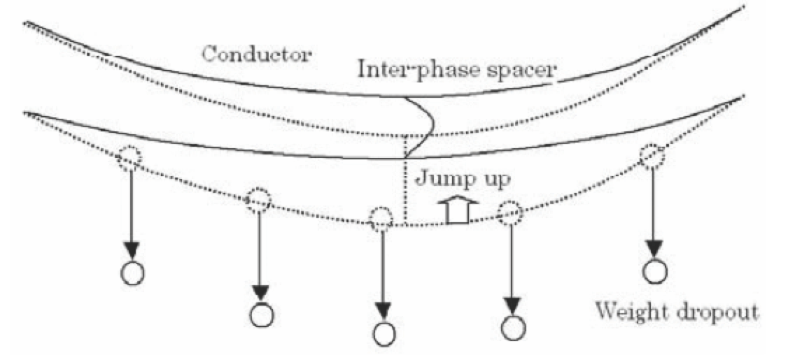 To simulate how this process can develop, a large-scale test set-up is utilized where the effect of an ice load is provided by several weight blocks that hang on the lower conductor by means of an electro magnet. When the magnet is switched off, the weights fall and conductor jumping occurs. In a typical such test, span length can be set at 70 m and the length of the spacer at 10 m while a twin-bundle ACSR 410 conductor is used. The interphase spacer will experience a fairly large, flexible, bending during the test but there should be no visual evidence of defect. The maximum stress in the FRP rod can reach a value of 290 MPa and once the stress is removed, the spacer must return to its original shape.
Installation of Interphase Spacers
After clarifying the electrical and mechanical loads as well as geometric data for the critical spans where interphase spacers are intended for application, it is necessary to decide where to locate them within the span. In this regard, a variety of factors usually have to be taken into account. However, it must be emphasized that symmetrical distribution lengthwise should be avoided since this placement could promote the development of standing waves in the span or sub-spans.
Some typical arrangements can be seen in the Figure below. Generally, the ideal number and location of the interphase spacers in each case depend on a line’s length of span.
CLICK TO ENLARGE
________________
RELATED ARTICLES:
Case Study for Application of Composite Interphase Spacers
Technology & Testing of Interphase Spacers
Resolving Problems from Poor Insulation Performance in Desert Environments