This edited past contribution to INMR by James Brady, an experienced Certified Level III Infrared Thermographer, reported on findings from line inspections conducted on behalf of utilities based in Florida, USA. These power suppliers share operation of a crucial transmission line that experienced insulator failures. Annual visual and infrared inspections intended to identify threats to reliability proved effective in rooting out certain issues but were unable to predict impending failures of polymeric insulators due to corona activity. Corona is not detectable through infrared inspection and its potentially destructive impact is also still not fully appreciated within the power industry.
Corona is an electrical discharge in the high electric field region of an insulator. This generally occurs in the vicinity of conducting surfaces but sometimes also near insulating surfaces due to ionization processes in air involving transfer of electrons being ‘knocked out’ of orbit and recaptured by atoms. This ‘recombination’ event releases energy in the form of light photons and is the glow commonly observed on transmission lines during low light conditions. The same effect can also be observed during daytime using solar blind UV cameras.
For corona activity to exist, a high electric field is needed in combination with how the shapes of energized components influence that field. For example, sharp edges, corners, points, tight radii or other irregular objects within a region of high E-field all have the potential to initiate corona. Fig. 2 shows three different insulator configurations with resulting electrical fields. Black, orange and yellow-colored areas show the highest gradients. Note how each different shape influences gradient and also the location of the most vulnerable sections of an insulator operating within a high E-field.
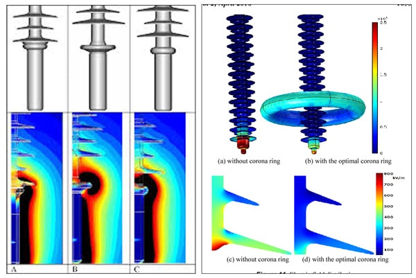
When utilities are considering which designs of insulators to put into service, manufacturers typically provide computer models to show where high E-field exists as well as possible interaction with the insulator. This process also determines whether corona rings/field grading devices are even necessary. Fig. 2 illustrates how corona rings serve to dissipate and transfer high E-field away from vulnerable areas of an insulator.
Corona activity can exist more easily, even under a relatively low E-field, with high temperature and low air pressure (i.e. higher altitude). By contrast, high humidity, without presence of condensation, has the opposite effect and requires higher E-fields to initiate corona. Condensation, if present, increases corona activity due to the irregular surface shapes produced by water droplets in a high E-field.
Corona can have several deleterious effects on electrical power systems and also on surrounding airwaves. These include:
• loss of power, i.e. electricity is lost to air during ionization;
• electromagnetic interference that affects radio and television broadcasts;
• audible noise;
• production of ozone (O3), that is especially destructive to the housing material of polymeric insulators
• creation of mild concentrations of sulfuric acid that is also harmful to polymeric insulators as well as to metallic conductors and other line components.
• creation of mild concentrations of sulfuric acid that is also harmful to polymeric insulators as well as to metallic conductors and other line components.
Detecting Corona on Power Lines
Infrared (IR) detection technology, while ideal in identifying hot spots in electrical power systems, has limited value when it comes to detecting corona activity. Experience shows that only advanced stages of corona can sometimes become visible using an infrared camera. Moreover, in order to increase the effectiveness of IR to detect corona, surveys must be carried out late at night, after the effects of solar gain on the equipment no longer exist. Even then, temperature differences can be slight and hard to detect. Given this, solar blind ultraviolet (UV) cameras and ultrasound devices are the most effective technologies to detect presence of corona. Ultrasound listeners, while highly effective for close range detection, suffer from waveform attenuation as distance between the corona activity and the device increases. Unfortunately, this is common whenever inspecting power lines. While parabolic dishes are available to minimize signal loss, these rely on operator know-how to follow the signal back to the source. The process can be slow and insufficiently accurate.
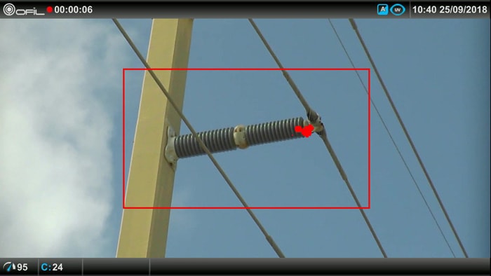
The ideal tool to detect corona activity is a solar blind UV camera. Unlike ultrasound, these have the ability to quickly and accurately locate corona activity, even from great distance. While easy to operate, the pictures produced require operator training and experience in order to correctly interpret findings. Like a thermal camera that operates within specific wavelengths in the electromagnetic spectrum, solar blind UV cameras operate within the UV spectrum. However, unlike IR cameras that collect natural radiant energy, corona cameras filter out natural occurring solar energy and capture only UV energy produced by corona and other sources. The camera, in its simplest form, is an overlay of a visual image with a non-solar UV event, i.e. looking through a corona camera allows a visual image with ‘starburst’ signals where there is corona activity (see Fig. 3). The stronger the activity, the more persistent and ‘louder’ will be the starburst signal.
Unfortunately, cost, combined with the specific need such cameras best serve, has caused this technology to still not be that widely used in predicative maintenance. The power industry community can benefit greatly from better understanding the potentially destructive nature of corona and the inspection technology that can best identify its presence before failures occur.
Solar blind UV cameras, while perhaps not yet sharing the popularity or recognition of IR cameras in the field of predictive maintenance, play a valuable role in detecting corona emissions and radio frequency interference on transmission and distribution equipment. In general, solar blind UV cameras are used mostly by in-house maintenance and inspection crews that work for large power utilities. Still, even here, these cameras are often underutilized given their potential and this is due to lack of full understanding of corona and its harmful impact on insulators, conductors and connections.
Transmission Line Inspected
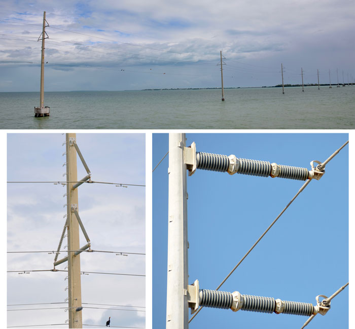
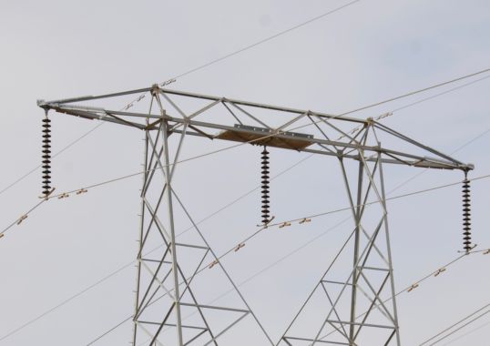
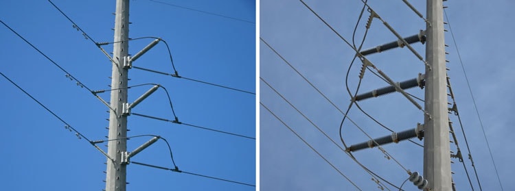
The 138 kV transmission line investigated as part of the contracted inspection program runs about 140 miles (200 km) and follows a highway linking south Florida with the Keys, therefore making several water crossings. Construction is a mix of polymeric and ceramic insulators with vertical, horizontal, V-shape, and dead-end configurations. Insulators in service on the easternmost section are equipped with corona rings but those on the middle and western sections are not (see Fig. 4). Older sections of the line have insulators approaching 20 years in service.
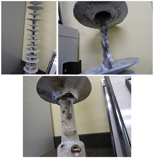
The polymeric insulators in service on this line are comprised of an inner fiberglass core rod attached on both ends to metal end fittings for attachment to pole and energized line. The entire assembly is encapsulated by a silicone rubber housing with alternating sheds. While reliable for beading water and encapsulating surface pollution, rubber is susceptible to tearing and can also degrade quickly under sustained leakage current from build-up of pollution combined with lack of rain. A key element of these insulators is the seal where the sheath meets end fittings. If moisture is able to penetrate into the interior, it can wick up through the rod and initiate internal partial discharges. Eventually, the sheath is punctured from the inside and corona activity begins on the exterior. This process continues until the insulator’s arcing distance becomes so short as to cause an electrical fault to ground.

Inspection Process
Both thermal and corona inspections were carried out from vehicles. Water crossings were inspected using shallow-draft boats. Corona inspection was carried out during daylight hours using an Ofil Luminar solar blind UV camera with telephoto lens that provides scanning capabilities out to several hundred yards. Since corona activity is dependent on temperature and humidity, sections of line were re-scanned at different times and on different days to assure findings applied to a range of possible atmospheric conditions. Weather parameters were also monitored and recorded through each day of the inspections. Also recorded were the GPS coordinates for each structure where some exceptional situation was identified and documented. This data was then used to generate a Google Earth KMZ file that that was incorporated into the final report. Infrared scans were completed using a Flir thermal imager equipped with 12-degree telephoto lens. Since it was anticipated that corona activity, if detectable, would have small delta-T signatures, it was imperative that solar loading on insulators be avoided. Therefore, scanning started on average four hours after sunset. Among the line components and equipment being inspected using both technologies were:
• Polymeric Insulators
◊ V String
◊ Dead Ends
◊ Horizontal V String
• Porcelain Insulators
◊ Dead Ends
◊ Horizontal Line Post
• Hardware / Connections
◊ Line Clamps / Shoes
◊ Post and cotter pin assembly on dead-ends
◊ Splices
◊ 4-hole pad connections on jumpers
◊ Static line / dead-end assemblies at poles
◊ Line Vibration Dampeners
Corona Camera Findings
The solar blind UV camera was successful in locating corona activity on various components. Examples and discussion of findings are shown below:
• Live end of polymer insulators on dead-ends (Fig. 5)
• 45-degree bracing insulator on horizontal V strings (Fig. 6)
• Porcelain post insulators at the segment bolt connection and at the live end of the line shoe / clamp (Fig. 7)
• Missing weights on vibration dampeners (Fig. 8)
• U-bolt clamp connections (Fig. 8)
• Cotter pin connections on dead-ends (Fig. 9)
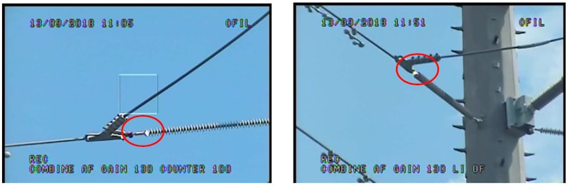
The corona pattern shown in Fig. 5 is typical of what was found on many dead-end structures, i.e. activity on the live-end seal where the polymeric sheath meets the fittings. Some 15 to 20 such problems were discovered during the survey.
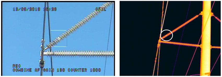
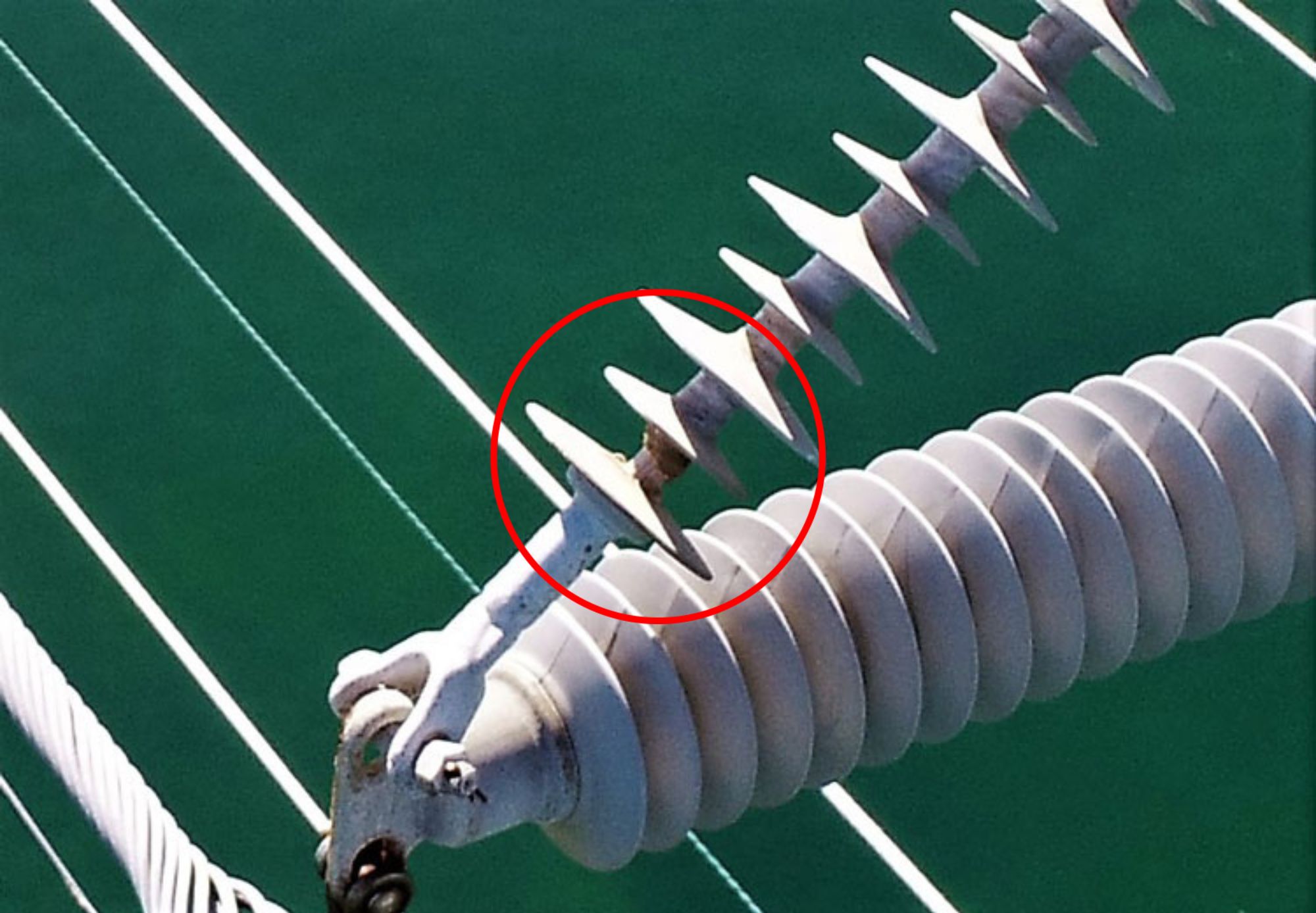
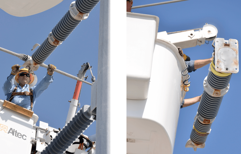
The corona pattern shown in Fig. 6 was one several findings showing serious corona damage on 45-degree bracing insulators. During the survey, three of the affected insulators were immediately replaced and another 5 or 6 scheduled for replacement over the following month. It was suspected that the smaller diameter of these insulators was causing the equipotential field to tighten significantly and generate a strong E-field, i.e. a favorable environment for development of corona. The failure mode in this case would be similar to that explained above, where moisture enters the interior of the insulator. The left image shows the migration pattern of the corona activity and also shortening of the ‘effective’ arcing distance from live end to ground.
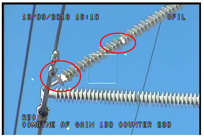
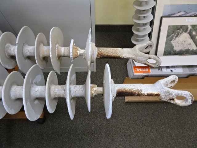

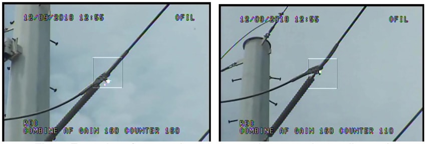
Fig. 7 shows corona activity on ceramic insulators. It is also possible that what is being seen is dry-band arcing caused by surface leakage current due to pollution accumulation. Note that arcing distance has been reduced significantly, especially in image at right.
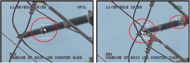
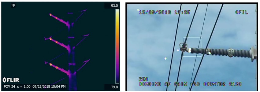
Fig. 8 shows corona activity on a point where a line vibration dampener weight used to be located (left photo). While not a critical threat to the system, the corona camera easily identified the damaged component, which is designed to control wind-generated oscillations and reduce stress on conductor strands. The photo on the right shows corona activity on bolt ends on a line shoe. Again, while not deemed an immediate threat to the system, the mild acids generated from corona will gradually accelerate oxidation on hardware.
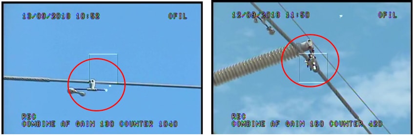
Fig. 9 show corona activity on the bolt pin that holds the line shoe to the dead insulator. Close-up inspection revealed that the cotter pin that prevents the bolt pin from backing out and dropping the line had seriously deteriorated due to long-term exposure to corona activity.
The problems illustrated above were all identified using a solar blind UV camera. Infrared camera inspection was also performed and below is a discussion of commonalities between these two technologies.

Infrared Camera Findings
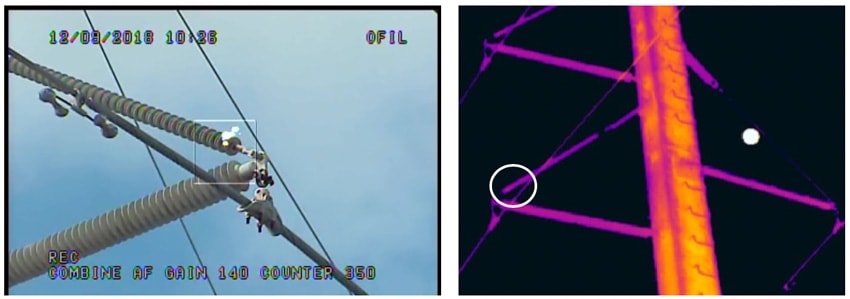
Infrared surveys were carried out after sunset to remove the effects of solar loading on insulators. This allowed better detection of small delta-T rises produced by corona as well as other defects not readily seen during a daytime infrared inspection. In most instances, findings from the corona camera inspection were not verified with the infrared camera. Fig. 10 offers an example where corona was detected at the live-end of 45-degree brace insulator but not detected with the infrared camera. Since these two images were taken on the same day but hours apart, it is possible the corona activity had ceased and was therefore not detectable with the infrared camera. But the more likely explanation is that the corona activity was not strong enough to produce a detectable heat signature. In this case, the ‘starburst’ observed with corona camera was intermittent and not as strong as might be observed on insulators with advanced stages of corona-induced damage.
The presence of corona was detected with the infrared camera but only in a few cases where activity was strong. Here, there was a persistent signal when viewed through the corona camera. Fig. 11 shows the heat signature of corona. Note that this signature is small and could easily be missed by the untrained eye.
Corona activity and possibly dry-band arcing on ceramic insulators was readily detectable with both the infrared and UV cameras. Fig. 11 shows typical such patterns on ceramic insulators with discharge.
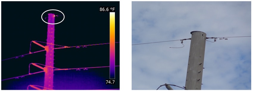
Although detecting corona activity was the main focus of this inspection, ancillary problems were detected with the infrared camera but not with UV camera. One such example was a hot spot detected at the dead-end connection of a static line jumper to a metal pole (see Fig. 12). The jumper wire had broken making the pole a ground point for lightning strikes. The hot spot is the manifestation of current flow generated from static electricity along the high line meeting resistance at the pole connection.
Use of Drones
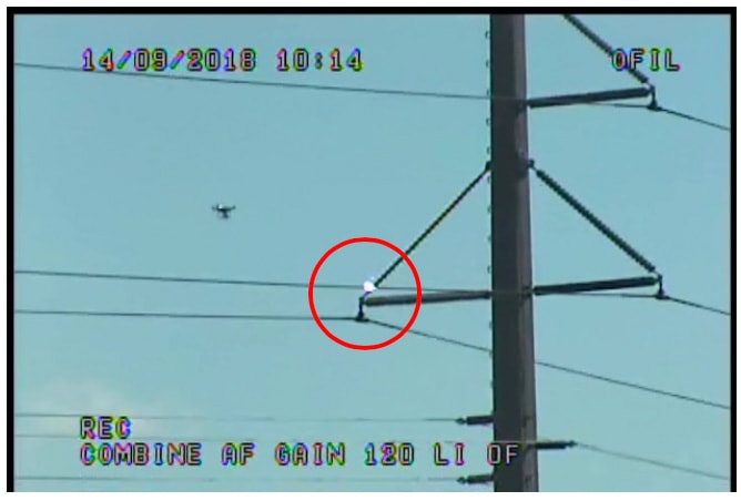
Drones were also used on this project to collect photos of corona damage found on structures that would otherwise not be easily accessible. Fig. 13 shows a drone in the process of capturing photos of corona activity on a pole that is quite a distance out over water. Use of a boat to collect such information would have taken several hours and tied up valuable utility resources. Here, the drone accomplished the task in less than 10 minutes and provided information that led to the decision to replace the insulator the following day.
Conclusions
This paper highlights the capabilities of merging infrared and solar blind UV cameras to detect problems that posed serious threats to the safe operation of a 138 kV transmission line. The utility company that owns this system knew it was vulnerable but had no other way of assessing to what degree. This line survey identified the vulnerabilities and allowed corrective action to be taken in time to avoid yet more outages such as had recently been experienced. Several findings from this survey proved critical threats to the operation of the system and had to be addressed immediately. Other non-critical problems were also found and these have been scheduled for short-term repair or replacement.
Utilities that own and operate transmission lines should consider adding corona inspection to their maintenance program, if not already the case. Corona can lead to a continuous process of degradation that affects insulators as well as other components that are vital for the safe and reliable operation of transmission lines. Indeed, the reason predictive maintenance specialist use multiple technologies is because no one tool that can meet all needs for identifying all possible problems. This case history demonstrates that fact and confirms that neither IR nor UV camera technology alone should be relied on as a single tool to evaluate the condition of transmission line assets. While the IR detected corona in some cases, it failed to always see it. Similarly, the corona camera detected all stages of corona activity but had no capability to detect resistance related problems that generate a heat signature.
Deploying drones to assess corona damage on equipment is a valuable and easy-to-deploy tool to complement any transmission line survey. In this case, the decision not to employ drones to carry the infrared and corona cameras was based on the fact that a ground survey was more time and cost effective given easy access to the line. Since this may not be case for every inspection, application of drones to perform such inspections should be considered on a case-by-case basis.