Environmentally-induced pollution of insulators is experienced by utilities worldwide and capable of leading to rapid deterioration in their performance under nominal voltage stress. The extent of this problem varies from place to place, even within the same system, since different pollutants and transfer mechanisms can be experienced. This can result in unique overall impact, especially when existing insulation properties are taken into account. Usually the problem is most severe on transmission lines due to the variety of service conditions that can be experienced along their routing. Subtle differences can even be detected from tower to tower, such as when one is at the top of a hill and the next located in a valley beyond.
Several methods have been proposed as part of the battle to maintain outdoor installation operating without failure under environmental pollution. In this edited past contribution to INMR by Consultant Dr. Kiriakos Siderakis, the problem of pollution maintenance was investigated for the case of substations based on service experience battling this problem on the Greek island of Crete.

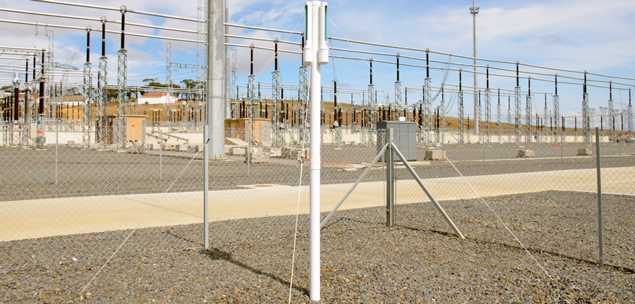
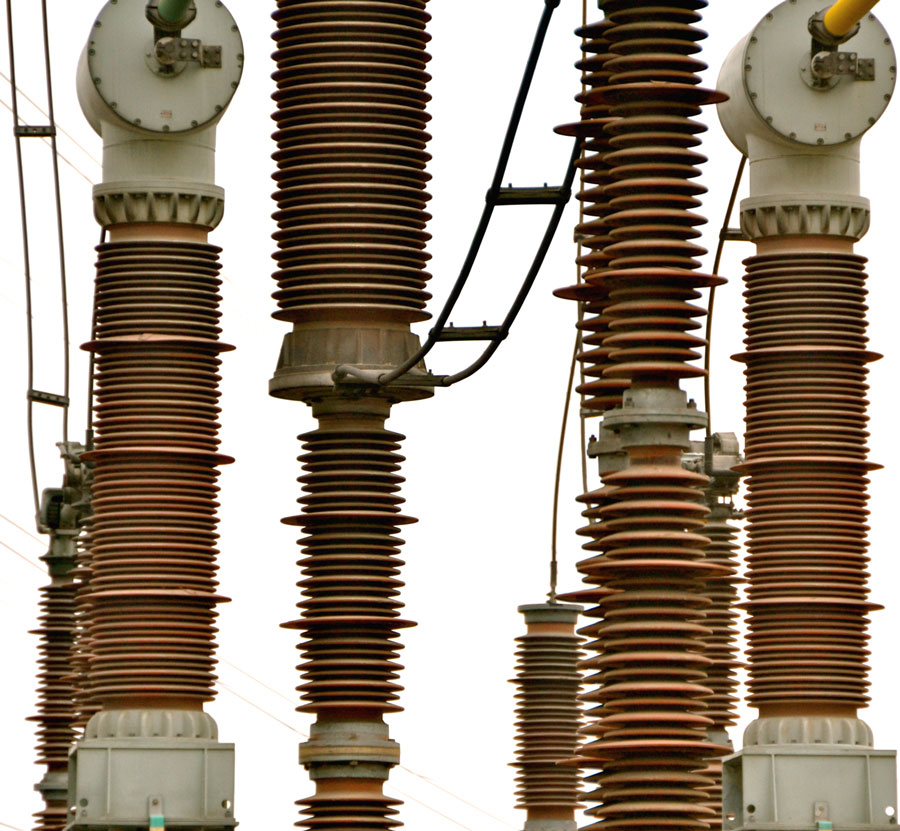
High Voltage Substations
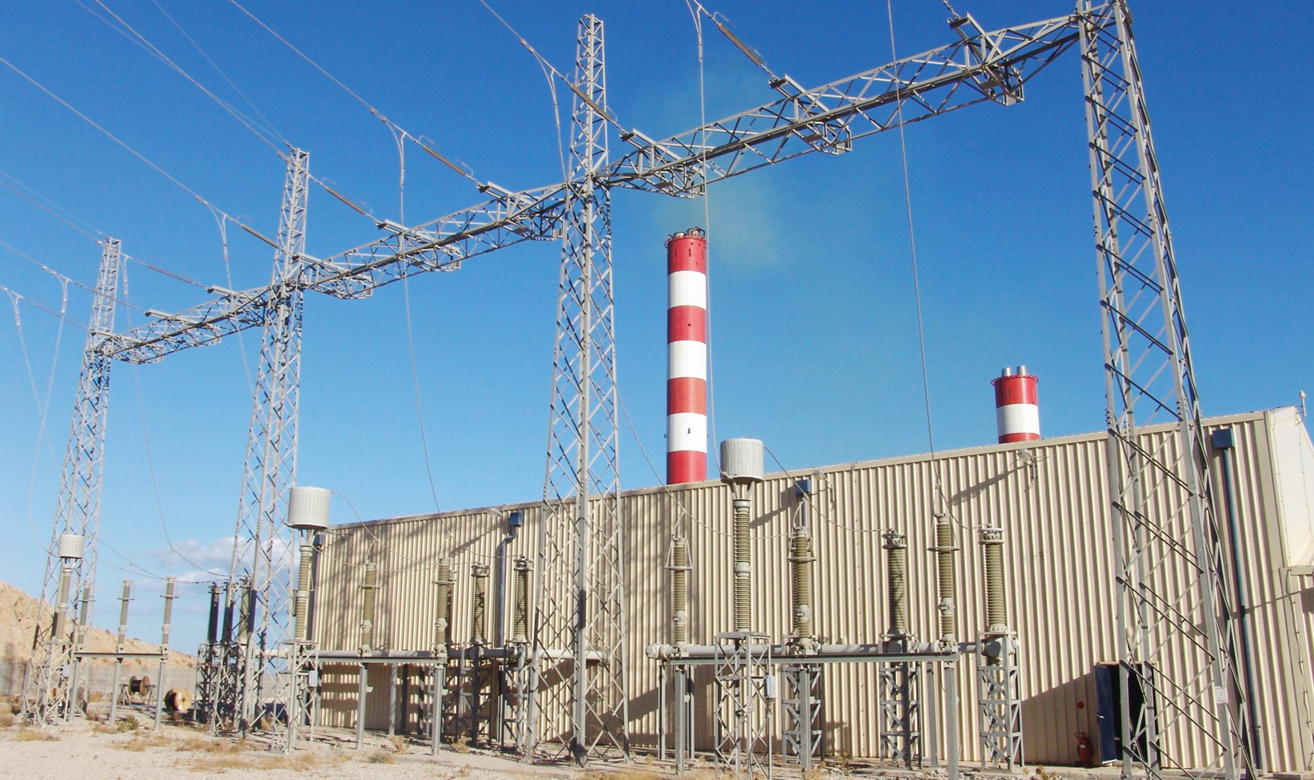
The high voltage substation is a node in the transmission system and any outage there typically corresponds to a far more severe impact on a power system than a corresponding incident on a transmission line. Therefore, from the reliability point of view, substation maintenance has considerable importance, which only grows with the corresponding increase in number of connected transmission circuits. Fortunately, as far as pollution is concerned, in the case of substations there are two important advantages compared to dealing with the same problem affecting overhead lines. First, a substation is a geographically concentrated installation and therefore the environmental conditions that affect it tend to be more uniform. Second, most substations are supervised, either locally by personnel or remotely. Consequently, the development of any pollution problem can be detected and suitable remedial measures applied in time. That explains why the incidence of pollution related outages at substations is relatively small compared to transmission lines.
Nevertheless, there are still variables that can complicate any effort to find permanent solutions for substations. One is the fact that there can be a large number of different insulators serving diverse equipment applications such as CTs, VTs, bushings, station posts, arresters, etc.. Each might have different geometries and therefore be subject to different pollution performance and maintenance requirements. Moreover, at least until some years ago, broad availability of composite housings for substation applications was still limited.
Pollution During Design Process
In the case of a new substation installation where pollution problems are likely to be a concern, methods and solutions are available to restrict or even eliminate possible negative influence from the environment. Table 1 summarizes the aspects usually considered during the design process.
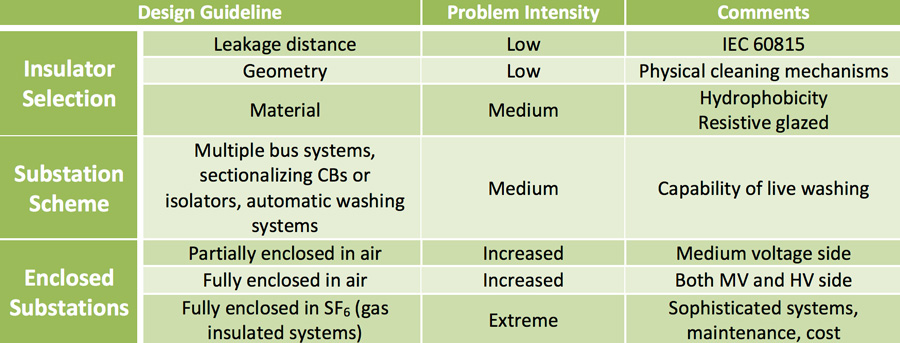
The first step is selection of insulation parameters and creepage distance. Required values can be determined using IEC 60815, which recommends specific leakage distance based on type and intensity of environmental pollution. Insulator geometry is also important and selection of a suitable profile must aim to take advantage of self-cleaning mechanisms. Otherwise, problems can still be experienced even when the basic leakage distance criterion is satisfied. Such instances, for example, have been experienced on Crete.
Use of composite insulating materials that provide a hydrophobic surface offers improved pollution performance that should be considered as well. But expected service life of these insulators then becomes another factor to consider, especially since replacement cost can be high and availability is another issue. Moreover, even with such materials, the most suitable insulator geometry must still be evaluated.
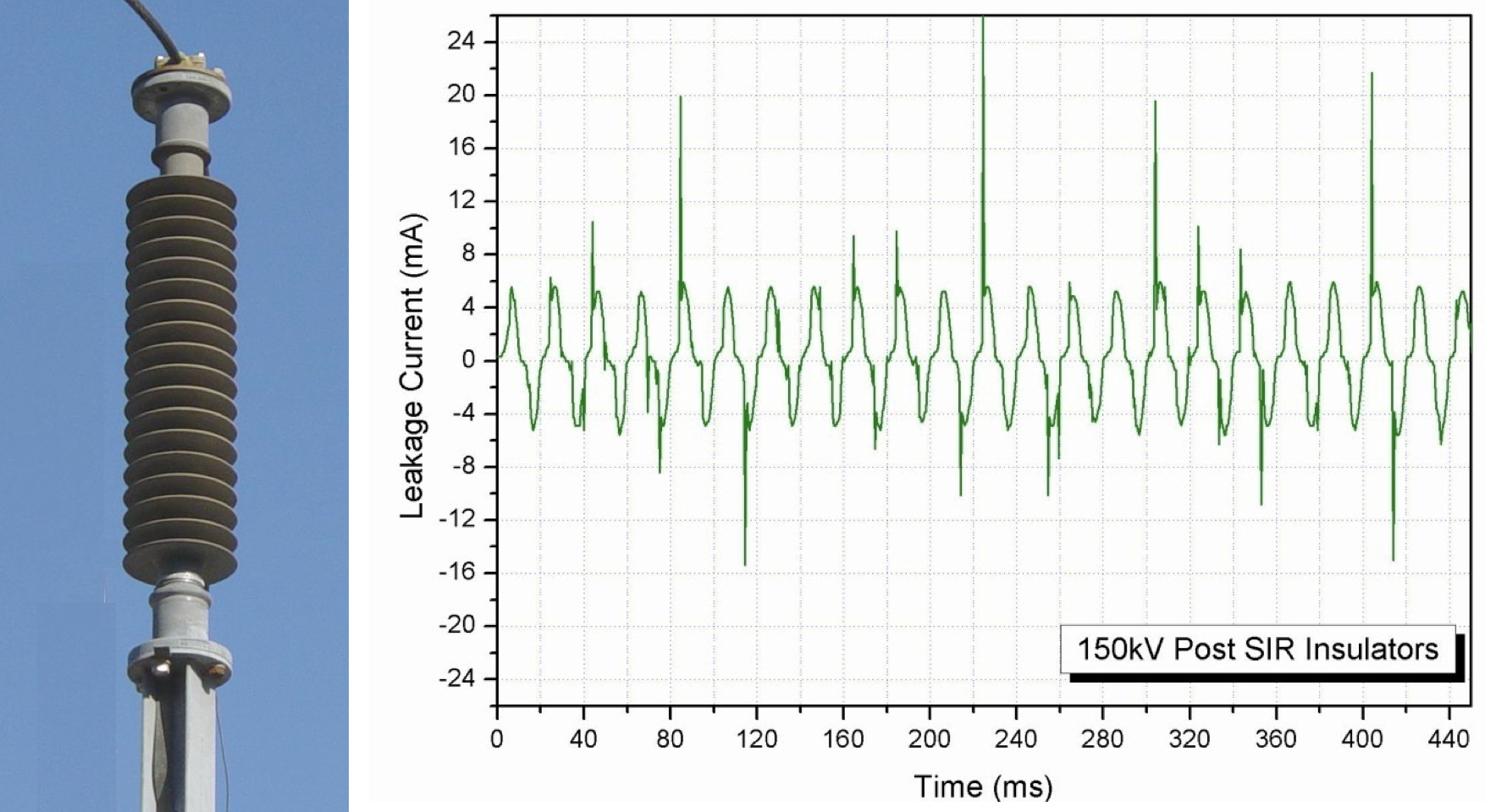
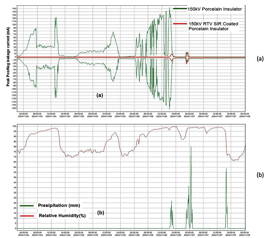
For example, new silicone post insulators at a 150 kV substation on Crete were monitored after installation using a leakage current measuring system. While it is evident that the insulators demonstrated satisfactory performance, increased activity was recorded whenever there was rain, most probably due to their geometry. Fig. 2b shows a typical leakage current waveform demonstrating this effect.
Substation scheme is also an issue impacting maintenance policy against pollution. In Greece, for example, live water washing is not an option and therefore different supply schemes must be available to avoid major power interruptions and thus maintain high reliability levels. The scheme usually implemented to deal with this constraint utilizes multiple bus systems and sectionalizing circuit breakers.
Finally, if expected pollution problems are severe and unavoidable, construction of enclosed substations should be considered. The majority of 150 kV/20 kV substations on Crete are partially enclosed with only the 150 kV side exposed to the outdoor environment. In addition, one particularly problematic 66 kV air insulated substation was fully enclosed. While in both such cases environmentally induced problems affecting insulators are limited, some control over the atmosphere at enclosed substations remains necessary due to risk of phenomena such as condensation.
One substation scheme that is fully resistant to environmental impact from the start is a GIS installation (i.e. fully enclosed in SF6). While risk of any pollution related problem is virtually eliminated and there is also a saving in space, other issues to consider include maintenance as well as installation costs.

Pollution Maintenance at Existing Substations
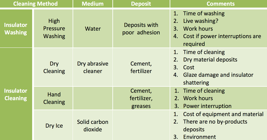
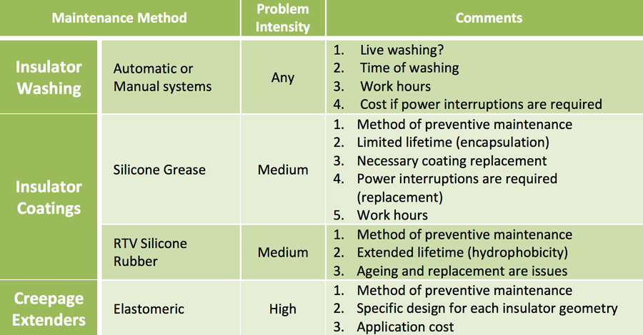
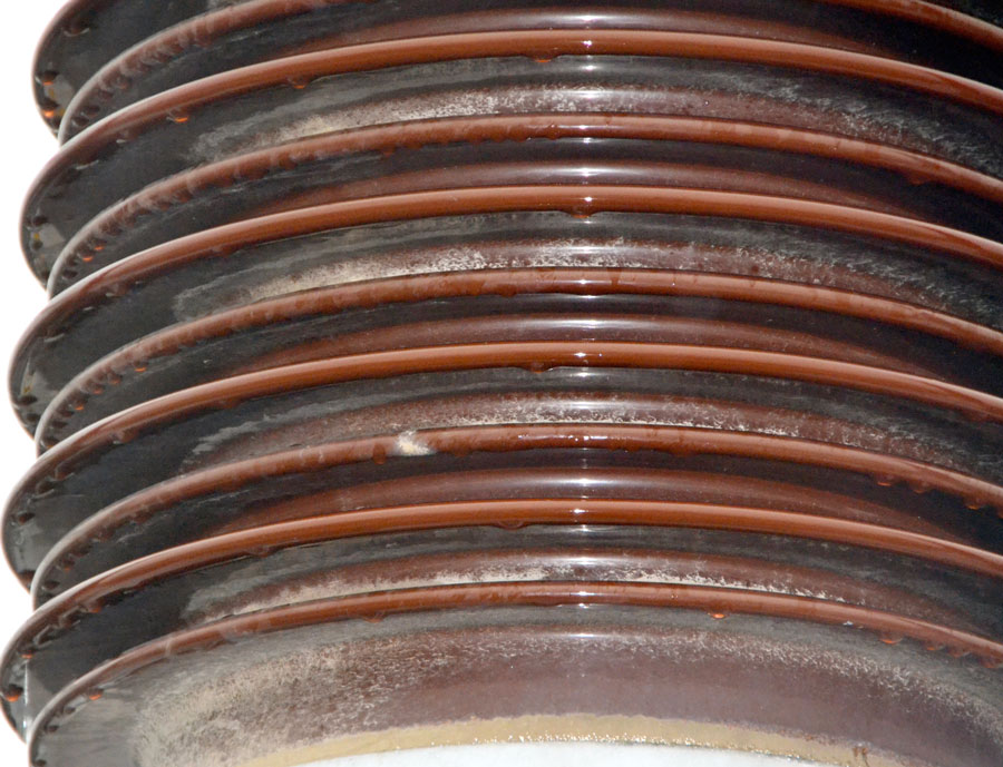
In the case of equipment already in-service at substations, the incremental investment to apply the remedial measures outlined in Table 1 can be considerable. Therefore, alternative measures must be found to improve the performance of existing insulation. The first action usually taken in this regard is cleaning the affected insulators. Table 2 outines different cleaning methods which are then selected based on parameters such as number of insulators to be cleaned, specific pollutants to be removed, possible by-products and corresponding application costs. These methods are made easier by the fact the affected insulators are typically located relatively close to one another.
For all different cleaning methods, the key factor is selection of optimum time to clean. This is usually an experience-based parameter that depends on local service conditions. If cleaning is performed earlier than necessary, critical build up of contaminants can still occur within a relatively short time and the basic problem remains. On the other hand, the longer cleaning is delayed, the higher the probability of an outage triggered by pollution.
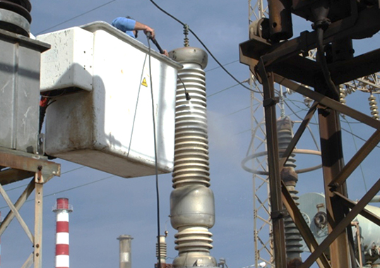
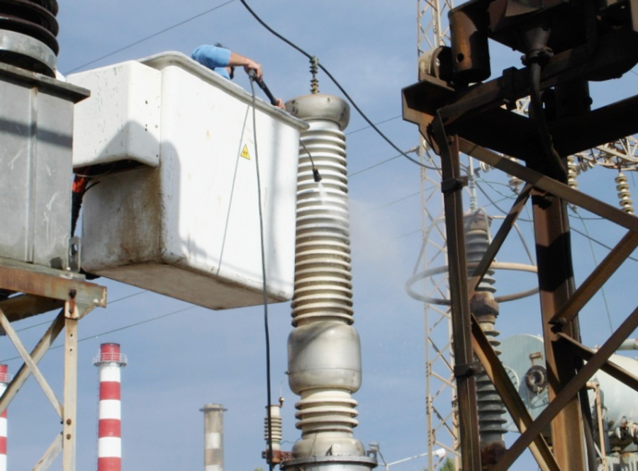
There is usually considerable cost related to most cleaning procedures, especially if they cannot be applied live. In this case, interruption in supply is required. This corresponds to deterioration in system availability since a portion of the substation is placed out of service. There may also be financial loss since interrupting power supply to a number of consumers may be necessary. It is worth noting that this loss can increase significantly in the case of step-up substations, for example if due to supply interruption one or more power units must be taken out of operation for several hours. One such case was recorded in Crete in the early 2000s when it was required to clean a substation in two parts at least twice each summer. In addition, total man-hours required must also be taken into account, considering that insulator cleaning is performed during hours of low load, i.e. during the night or early morning.
While cleaning insulators is certainly one way to ensure performance under pollution conditions, selection of the optimum cleaning time is critical (since it is a reaction and not a preventive measure) while all associated costs must be calculated, especially if not applied live. For these reasons, a more advanced approach aims to improve the corresponding surface performance of insulators under pollution. Different types of insulator coatings exist, however the most common types are silicone grease and RTV silicone coatings. Their use constitutes a preventive method since they can be applied at a time convenient for the utility. Over their operational lifetime, such coatings are capable of suppressing the impact of pollution and eliminating any related insulation problems. In both cases, suppression of leakage current is achieved by providing a water repellant surface that does not permit formation of a surface film of conductive contaminants. The main difference between the two lies in method employed to maintain water repellency, even as contaminants deposit on the surface.
In the case of silicone grease, all deposited contamination becomes encapsulated within the material’s volume and, as a result, the insulator surface remains clean. This process, however, suggests that there is a saturation point where no additional contaminants can be encapsulated. This point marks the end of its effexctive service life and the material must then be removed. Otherwise, there is a risk of even worse pollution performance than an insulator without grease. On Crete, for example, the average life of silicone grease coatings has been found to be only about 6 months and they must be applied and then removed twice each year. This has limited application mainly to critical equipment.
A water repellant surface is also the primary feature of RTV silicone coatings. However, unlike greases, there is no encapsulation feature but rather a hydrophobicity transfer capability that is sufficient to change the initial hydrophilic behavior of the deposited contamination film to hydrophobic. As a result, although deposited contaminants remain (i.e. with no encapsulation), the surface continues to be hydrophobic. This offers considerable improvement versus grease since accumulated contamination is still exposed to various cleaning mechanisms such as rain and no level of saturation is reached. In addition, service life can exceed 5 years and, in some cases, more than 10 years. RTV coatings should therefore be considered as an efficient pollution countermeasure at most substations. They can be applied at a time convenient for the utility on any insulator, regardless of material, type of equipment and shed geometry. In the case of Crete, total cost for application of all the RTV coatings in use by 2010 was less than the corresponding cost of washing at the most problematic substation over a period of only three years.
Of course, there are possible drawbacks that must also be considered. These include ageing, maintenance and finding the optimum time for replacement along with the corresponding cost (labor and materials). Still, their preventive features and the possibility of large-scale application are considerable advantages that distinguish this maintenance alternative from others. Unfortunately, coatings cannot fully counterbalance lack of proper creepage distance on inappropriately dimensioned insulators, given the pollution environment.
If specific leakage distance is insufficient, use of elastomeric creepage extenders might be obligatory. As with RTV coatings, extenders can be applied on any insulator type but must be specifically designed for the unit’s geometry – something that limits large-scale application and also increases application costs. Therefore, it is a method usually adopted for severe conditions or when the methods mentioned above are not sufficient used alone.

Application of RTV Coatings at Substations on Crete
The first application of RTV coatings on Crete began in 1998 at the Linoperamata 150 kV step-up substation, which became fully coated a few years later. Other of the island’s substations have since been coated and thousands of kg of coatings are already in service at 66 kV and 150 kV substations on the islands of Crete and Rhodes. Since initial application, surface activity due to pollution has been substantially suppressed and no flashovers occurred, even though all washing was suspended on coated insulators. The application can therefore be considered a success by any measure. However, with coatings that exceed a life of 5 years and often closer to 10, there have been concerns how best to evaluate the material’s continued reliability and then decide on any maintenance actions. Under normal service conditions, evaluation of the coatings was based mainly on empirical observations, such as surface discharges, noise and visual effects from corona during the night. Leakage current measurements were also performed and these verified the improvement achieved by applying the coatings.
A comparison is provided in the graphs of Fig. 9. In the first illustrates monthly distribution of accumulated charge recorded on the surface of monitored 150 kV porcelain post insulators (i.e. average behavior). It is evident that surface activity takes place, as expected, mainly during the dry summer months, especially from August to October. In the second, the same distribution is shown this time for RTV coated insulators having the same geometry, over the same period of time and installed at the same location. Values of accumulated charge (vertical axis) are therefore indicative of the improvement achieved.
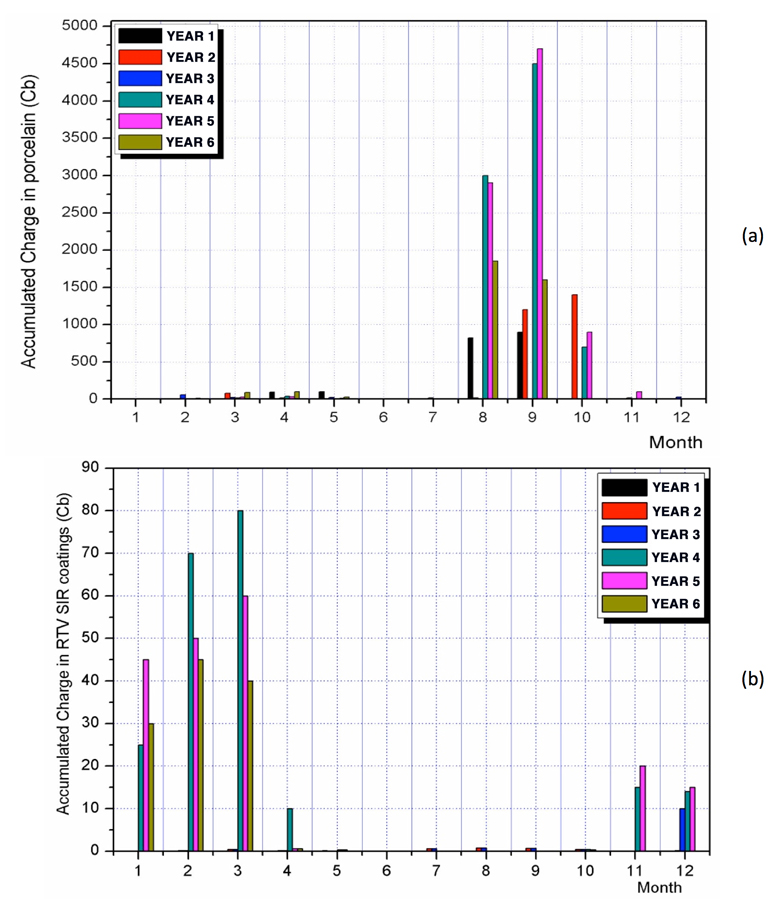
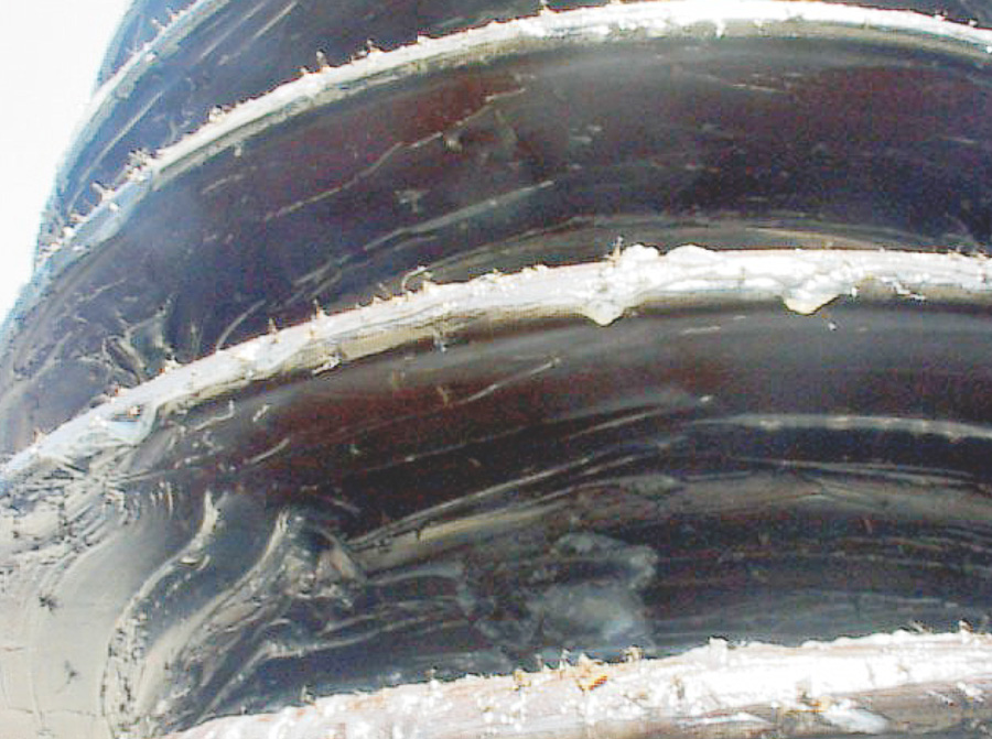
It is worth noting that period of activity is different in each case. Although the main pollution problem is experienced during the summer, for RTV coatings surface activity increased mostly during the winter months, especially from November to March. This phenomenon has been correlated to influence of the wetting mechanism, which is different for the two seasons. During the summer, the primary wetting mechanism is condensation while during the winter it is precipitation. Fig. 10 provides a typical example of the influence of these alternative wetting mechanisms on the two different insulator surfaces. In the case of condensation, surface activity is observed only on the porcelain insulator. On the other hand, during periods of rain, activity is seen on both types of insulators. For the first incident, activity on the coated insulator was considerably less than on porcelain. But in the case of the second incidence of rain, the same levels of activity were observed. Finally, in the third incident, no activity was present.
Monitoring leakage current, while a valuable tool to fully understand behavior of RTV coatings under such service conditions, is not by itself sufficient to support complete evaluation of coating condition. Performance improvement was verified but these measurements were not able to detect the full impact of any ageing phenomena.
Application of this methodology is typically limited to only a small number of insulators due to costs. Furthermore, it is often not possible to monitor the full range of currents with the required accuracy. In this case, for example, currents less than 1mA could not be recorded and this was one of the reasons there was no reliable data to compare the coatings offered by different manufactures. Finally, the property of greatest interest in this case is surface hydrophobicity and its corresponding recovery mechanism. Both closely correlate to material properties and can be evaluated only on a macroscopic scale by looking at leakage current alone.

To improve available information on the condition of different coatings installed on Crete, hydrophobicity measurements using the STRI Guide were carried out. These findings demonstrated that, even for the oldest coatings, a hydrophobic surface behavior could still be observed. However, these types of measurements evaluate only the existing surface condition of the coated insulator and offer no information regarding loss and recovery of hydrophobicity (i.e. the stability of this key property). In addition, it is mostly a subjective method and sometimes successive measurements can be at odds with one another.
By most measures, application of RTV coatings on Crete has proven a success, especially given that the payback period of the corresponding investment was less than three years. However, a different era has since been entered, as concerns have come forward regarding how best to evaluate the residual life of coatings and decide on future maintenance needs.
Concerns Regarding Application of RTV Coatings
The first concern for these types of coatings is material selection. Since there are a growing number of different manufacturers worldwide, from the user point of view there is a need for standards with related methods and well-defined criteria to evaluate the quality of any RTV coating under laboratory conditions, before application. Then, after application, the required methodology to monitor condition and performance of these coatings becomes the main issue. While measurements of leakage current and hydrophobicity can be made, experience gained from application of these methods on Crete has suggested that they are not sufficient to provide the complete picture.
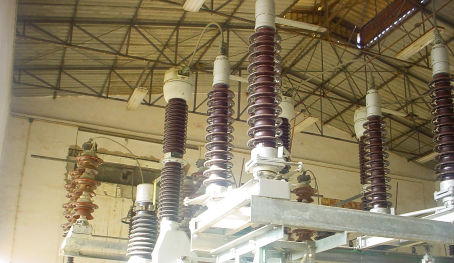
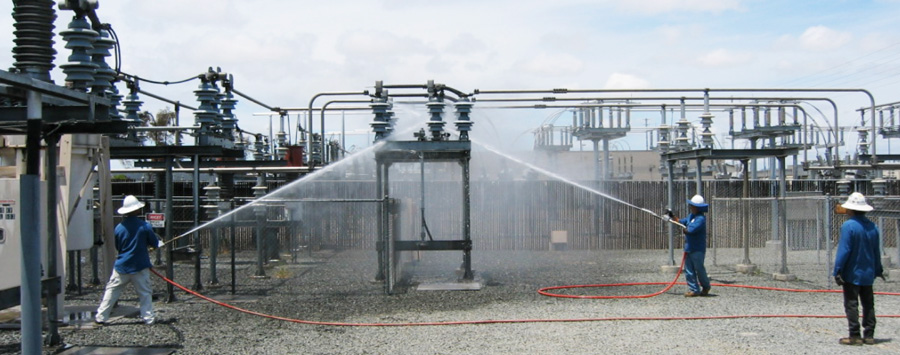
It is evident that some material analysis is also required and the question arises as to which parameters must be evaluated and what techniques should be employed. Then, if these methods detect any ageing, the next issue becomes deciding on what remedial actions are required to protect the coatings and extend their service life. Insulator cleaning or high-pressure washing (as in Fig. 8) could probably be employed in some cases. In others, it may be necessary to re-coat. However, it may not be sufficiently clear which should be employed and when to achieve improvement in coating performance with no risk of further deterioration.
Finally, establishment of well-defined end-of-life criteria is necessary in order for users to select the optimum time for replacement or re-coating. In this case, development of standardized methods to remove the previous layer of coating becomes important, considering that any re-coating is probably mostly a temporary remedy. In other words, a complete monitoring and maintenance strategy must be established from the time of coating selection and application. Only this way will it be possible to fully evaluate coating condition and determine when is the correct time for further remedial actions.

Conclusions
Anti-pollution maintenance of insulators at high voltage substations is an issue confronted by virtually every utility worldwide. The main factor that distinguishes the situation for substations from transmission lines is the relatively homogenous service conditions at each station and the corresponding high cost of the equipment to be protected.
In the case of already installed equipment, available remedial measures must be able to improve the pollution performance of existing insulation since the cost of replacement can be considerable. Several methods are available but RTV coatings appear to be the most promising, providing a protective remedy over a long service life. In Crete, large-scale application of such coatings has allowed improved insulation performance, as verified by leakage current measurements and the need for no additional remedies. Nonetheless, there are still concerns to be addressed when it comes to selection of coating from different suppliers, the necessary monitoring and maintenance they might need and finally optimum replacement time and method.