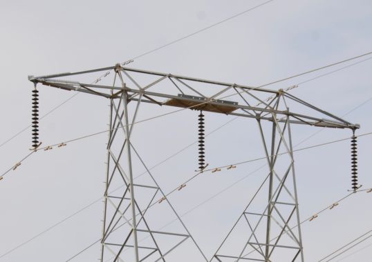
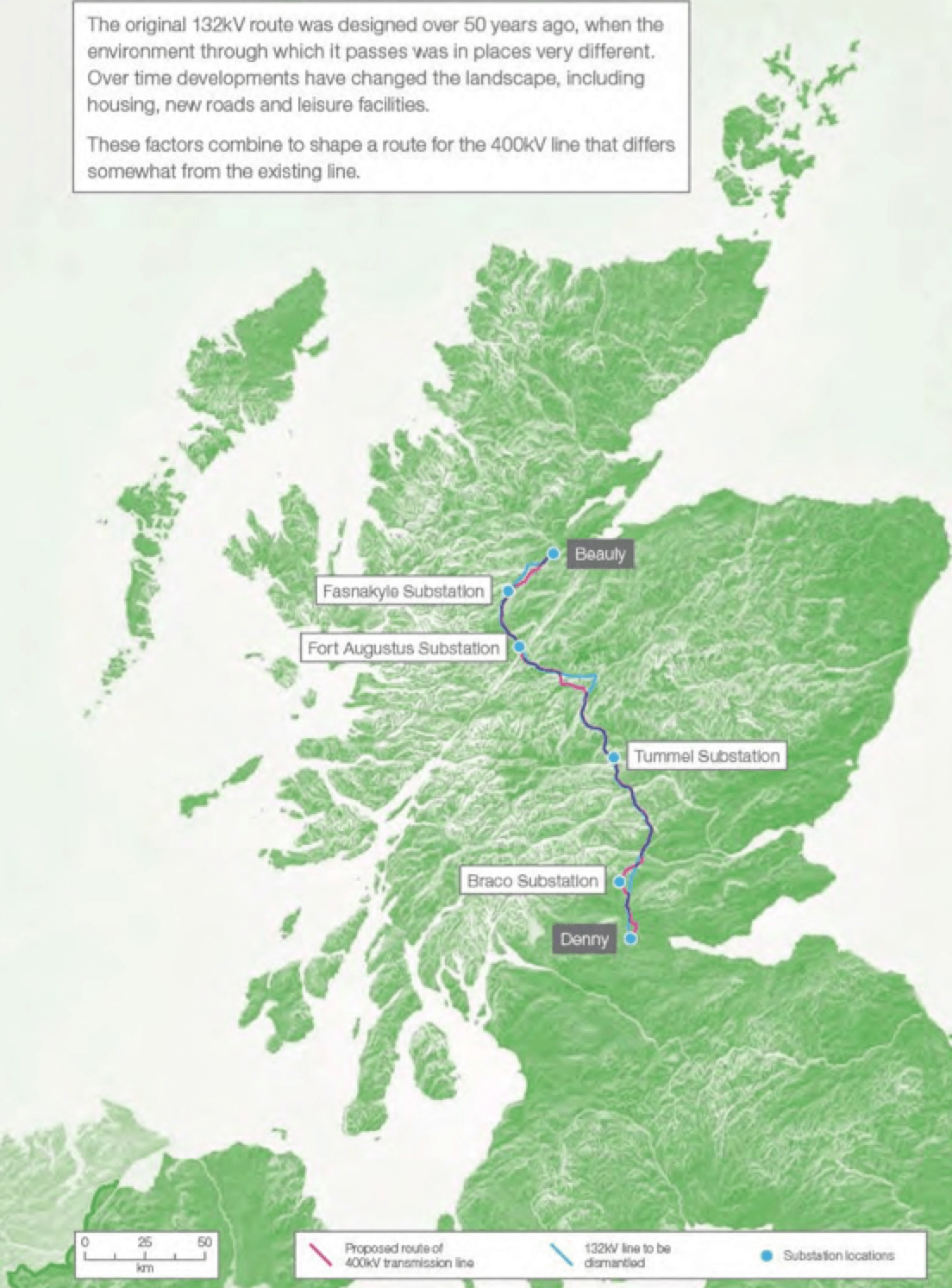
This edited past contribution to INMR by Stephen Bell of K-Line Insulators in Canada reported on application of interphase spacers on a 400 kV overhead line built to transmit power from increased renewables generation. The line, running from Beauly Substation to Denny North Substation in Scotland, follows a similar route to an existing 132 kV line and traverses some 220 km of hilly terrain exposed to high winds with wet snow accumulations on conductors during freezing of from 75 to 100 mm diameter. Composite type interphase spacers had already been installed on the 132 kV line to mitigate galloping under these severe weather conditions. A decision was made to also install similar interphase spacers on the two-bundle phase conductors of the new 400 kV line to ensure reliability of this key link in the Scottish and Southern Energy (SSE) Grid Systems.
Conductor Galloping Under Wind, Ice & Snow
Galloping is large amplitude, low frequency, wind-induced oscillation of overhead lines. In most cases, there is an ice accretion on the conductor that modifies its normal cross-sectional shape such that it becomes aerodynamically unstable. Amplitudes are mainly vertical and typically range from +0.1 to 1.0 times the sag of the span while frequencies usually range from 0.15 to 1.0 Hz. Driving wind can vary between 8 to 72 km/h (5 to 45 mph) at a 10 to 90 degree angle to the line and can be unsteady in velocity or direction.


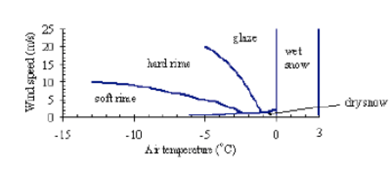
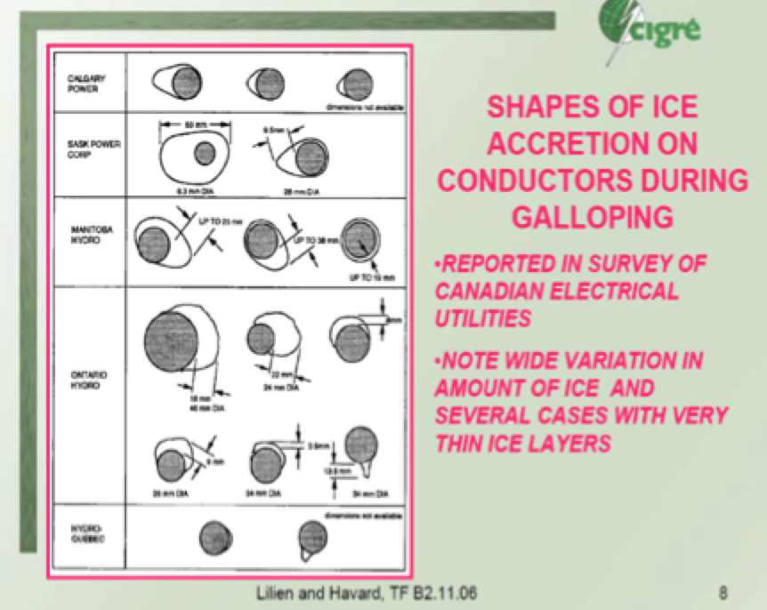
The types of ice and snow that can accrete on overhead conductors are rime ice, glaze ice, frost, dry snow and wet snow (see Fig. 3). Rime ice is in-cloud icing where super-cooled droplets impact and then freeze onto a substrate. Glaze ice can be precipitated or formed in-cloud when droplet freezing time is sufficiently long to allow a film of water to form on the accreting surface. Wet snow accretion is observed when air temperature is between 0°C and 3°C and can occur under any wind speed. The various possible shapes of ice accretion on galloping conductors were reported in a past survey of Canadian utilities (see Fig. 4).
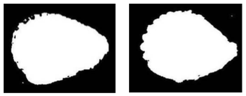
Glaze ice accreted on overhead conductors is more commonly considered in analysis and testing studies of galloping than are other types of accretion. Thin layers of glaze ice on a conductor have a rounded shape (see Fig. 5).
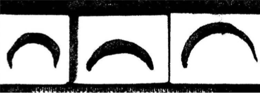
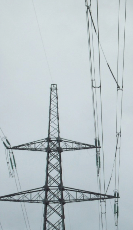
Elevated sections of the Beauly-Denny route where galloping occurred in the past on the pre-existing 132 kV line have experienced wet snow and rime ice accretions. Rime ice does not create a conductor shape susceptible to galloping. However wind-driven wet snow packed onto the windward sides of conductors forms a hard, tenacious deposit with a sharp leading edge (see Fig. 6) that is highly unstable aerodynamically. Bundled conductors are especially susceptible in this regard since their high torsional strength prevents accreted snow weight from twisting the conductor to reduce the concentration of the accretion into the sharp leading edge. Shape of conductor ice and snow accretion thereby affects conductor galloping movement.

Predicting Movement of Conductor Galloping
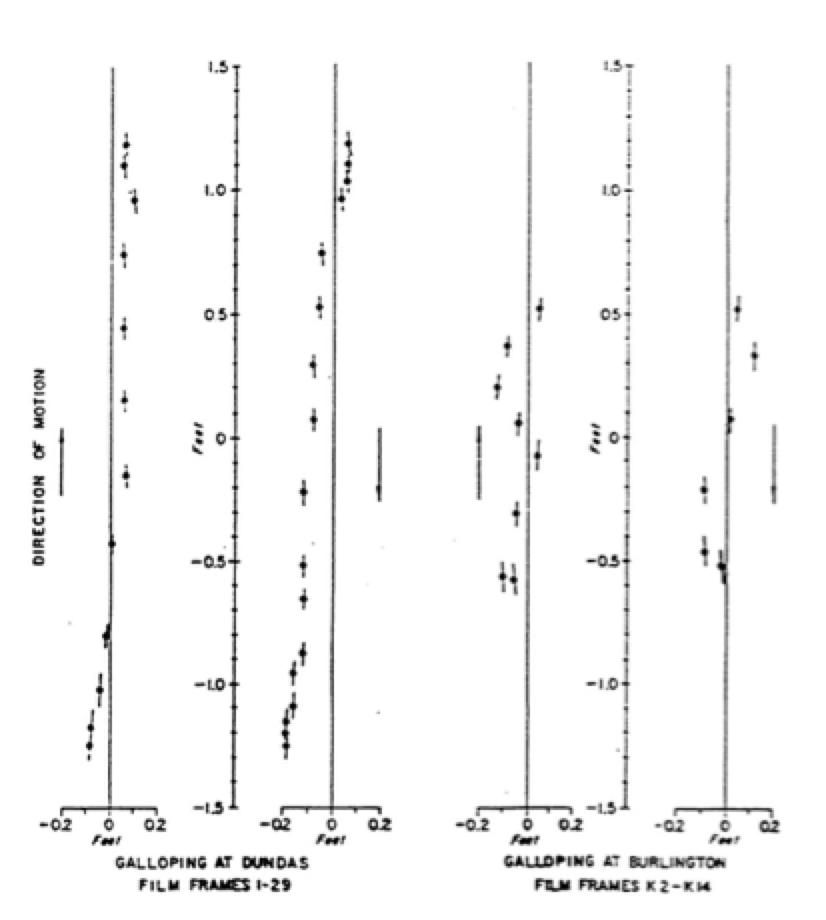
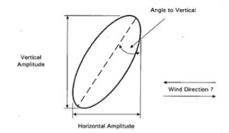
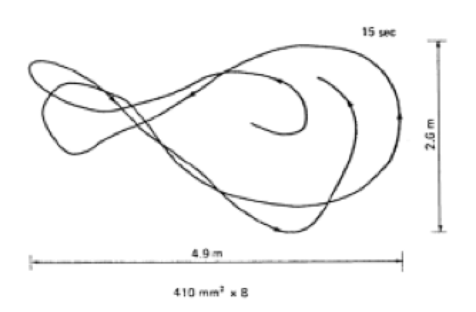
Knowledge of galloping conductor movement has come mostly from field observation and utility guidelines on how to observe and record galloping events have been developed. These include reporting format as well as instructions for camera and video recording. Plotting movement recorded by multiple photos of galloping conductors with glaze ice shows mostly vertical motion (see Fig. 7). A (galloping) envelope around recorded points has an elliptical shape (see Fig. 8).
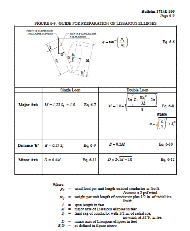
Lissajous ellipses can be calculated for conductors with glaze ice in relatively flat, open areas (see Fig. 9).
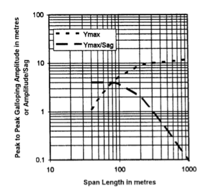
Field observation of galloping for glaze ice covered conductors were used here instead of calculations and predicted peak-to-peak galloping amplitudes of 10 m for the new line (see Fig. 10).
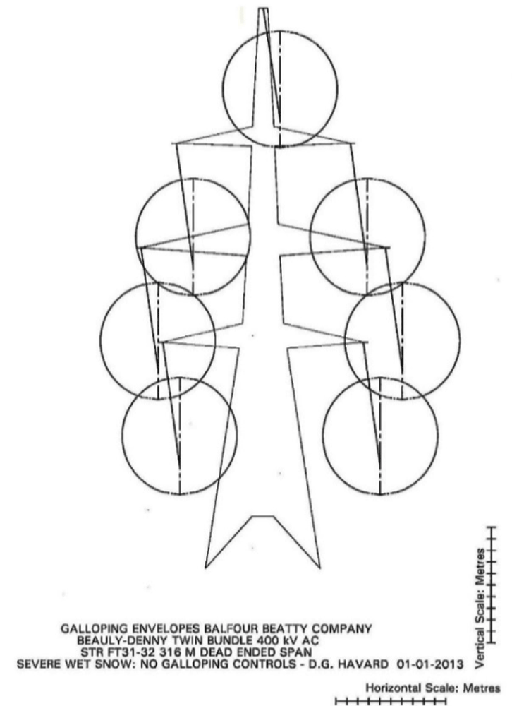
The galloping envelope was also changed to be circular. Wind tunnel studies on conductors with glaze ice versus wet snow accretions have shown the wet snow profile to be more aerodynamically unstable and that more wind energy transfers to the conductor. Moreover, wet snow galloping occurs over a wider range of wind conditions. For example, galloping studies on bundled conductors with wet snow in Japan showed large horizontal movement (see Fig. 11) and support using such a circular galloping envelope.
Wet snow circular galloping envelopes for the new 400 kV line would overlap if interphase spacers were not used (see Fig. 12). Also, horizontal movement with wet snow would only increase this overlap.
Required galloping envelope separation is based on voltage to flashover between phases or between phase and earth (see Fig. 13).
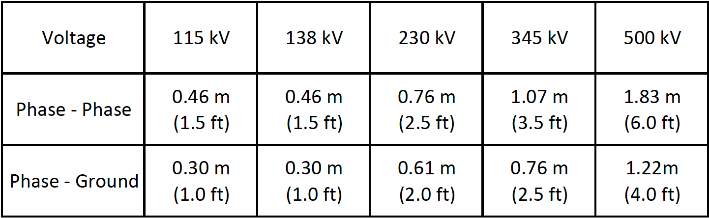
The envelope separation to avoid flashovers at 400 kV is interpolated to be 1.3 m phase-to-phase and 0.9 m phase-to-earth.
Potential Effects of Conductor Galloping
Movement of conductors such as in galloping can result in:
1. contact between phase conductors or between phase conductors and overhead ground wires, resulting in electrical outages and conductor burning;
2. conductor failure at support point due to the violent stress caused by galloping;
3. possible structural damage; and
4. excessive sag due to overstressing conductors.
Vertical galloping loads on suspension structures can be 2 times static vertical loads from ice-covered conductors while horizontal galloping loads on dead-end structures and conductors can be 2.8 times static ice related tension loads. Structure and conductor fatigue strengths, not static strength, therefore must be considered under galloping. Application of interphase spacers would reduce dynamic loads in proportion to the square of the amplitude of motion.

Mitigating Conductor Galloping
Use of interphase spacers was found to be the most cost effective solution to reduce galloping amplitude. For example, shortening spans would reduce amplitude but intended span length in some instances would need shortening by 50% thus requiring an additional tower. The option of increasing vertical phase spacing was reviewed as well. But studies on conductor tension versus galloping amplitude indicated that tension changes would not adequately reduce galloping amplitude in the case of this new line.
Effectiveness of application of interphase spacers has also been confirmed not only by experience with the pre-existing 132 kV Beauly-Denny transmission line but also by results from an international Interphase Spacer Survey conducted by CIGRE.
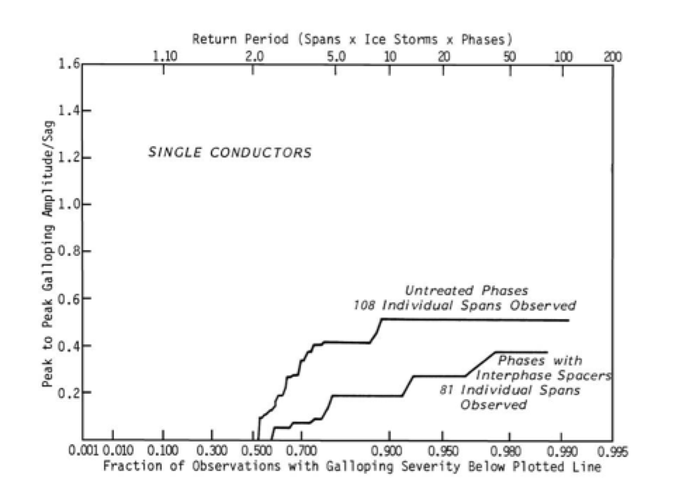
Documented field observations have also confirmed reduced galloping motion if interphase spacers are installed (see Fig. 15). This data was then used to predict a 50% decrease in galloping amplitude with application of interphase spacers on the new 400 kV line’s phase conductors. Reduced circular galloping envelopes gave the separation needed between these envelopes to prevent flashovers between phase conductors (see Fig. 16).
Span Considerations for Conductor Galloping
Interphase spacers were to be used for suspension and dead ended spans on the new line. Galloping in suspension spans can couple to adjacent spans as suspension insulators swing while dead ended spans on the new line would not couple to adjacent spans. Location of maximum galloping amplitude varies with span length for common shapes of galloping mode (see Fig. 17).
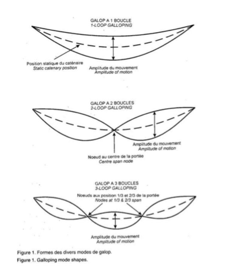
Field tests of bundled conductors in Japan showed that galloping in dead ended spans is often a two-loop mode of oscillation. Moreover, bundles have large amplitudes of galloping when torsion and vertical oscillations are in-phase.
Four interphase spacers per span (see Fig. 18) were used on the new line to maintain required conductor spacing during observed mixed mode galloping in the field, with top and bottom phases having single loop galloping and middle phase having two loop galloping (see Fig. 19).
Interphase Spacer Design
Interphase spacers for the new line were designed with hinge joints for phase conductor spacing ranging from 8.5 to 10 m. Hinged designs have been used for years for long interphase spacers to prevent excessive bending of the insulator (see Fig. 20). Interphase spacers do not need to resist the conductors moving together. Rather, they serve to reduce maximum galloping amplitude in the span by preventing the phase conductors from moving apart at locations where they are installed.

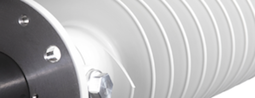
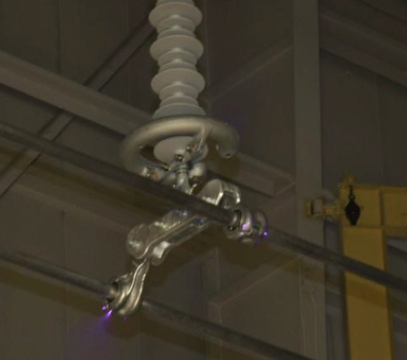
The composite insulator used for these interphase spacers (see Fig. 21) is lightweight, non-brittle and has a mechanical strength of 120 kN (SML). Moreover, its silicone rubber housing features excellent hydrophobicity, making it suitable even in high pollution environments. In addition, to ensure reliability of this important line, the galvanized forged steel end fittings are Charpy compliant for cold temperature impact loads.
Electrical characteristics of interphase spacers are based on line or phase-to-phase voltage and in this case are equipped with corona rings at both ends. Interphase spacer BIL is 1.2 times system BIL. Flexible bonding straps are used at the two-bundle spacer connections and also at hinge locations since the interphase spacer is alternately compressed and extended by conductor movement. In addition, semi-conducting rubber inserts are used in the two-bundle spacers for the twin 37.26 mm diameter ‘Araurcaria’ conductors.
Validating 400 kV Line Interphase Spacer Design
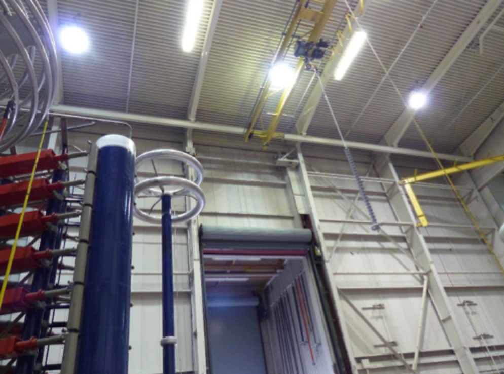
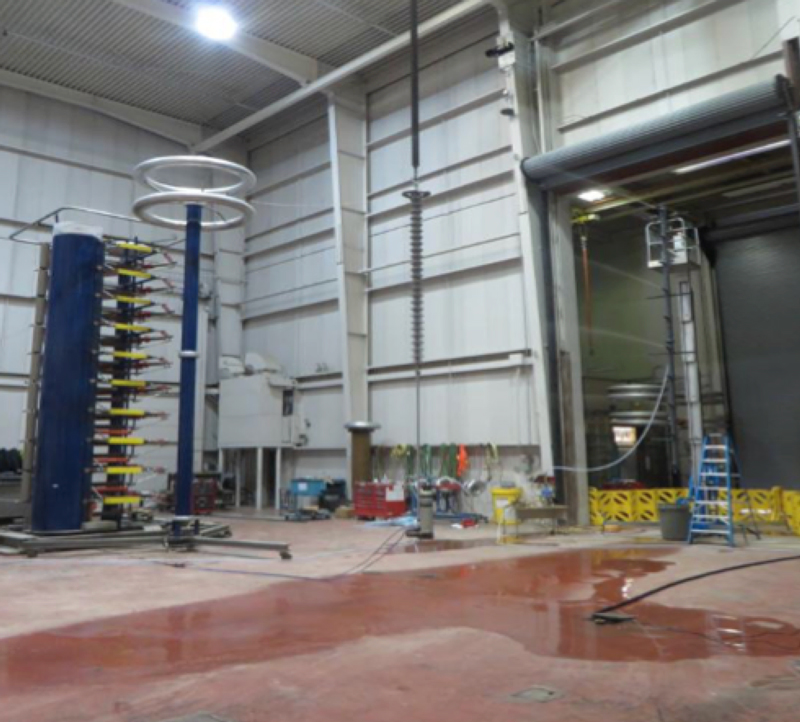
Electrical testing of these interphase spacers included dry lightning impulse (Fig. 22), wet switching impulse (Fig. 23) as well as RIV noise and corona extinction tests (Fig. 24), according to both CSA and IEC standards. Where applicable, the spacer was installed during these tests. The 2-bundle spacer was tested as well, following IEC 61854 and user specifications. Evaluation of performance also included longitudinal slip of the conductor in the clamp and indentation of outer conductor strands when the clamp was tightened. Electrical resistance of the rubber inserts used in the clamp was also measured to ensure these were semi-conducting.
Interphase Spacer Installation
Appropriate packaging was developed to support and protect the interphase spacers during transport. Cleaning, handling and packaging of composite insulators are being covered in IEEE 987, a Guide for Application of High Voltage Composite Insulators for Overhead Electric Power Lines. Interphase spacers can be installed with lines de-energized or using various live-line work methods (Fig. 25).
Other Interphase Spacer Applications
Interphase spacers are used on distribution lines as well as on single or bundled conductor transmission lines. Their role is to reduce conductor movement during wind induced vertical galloping or horizontal swinging or whenever snow drops from a lower conductor such that it rises rapidly toward the conductor above. Reduced conductor movement allows for reduced phase spacing, thereby lowering structure height as well as required right-of-way width. Interphase spacers can even be offered with turnbuckles to allow length adjustment for varied phase spacing.

Summary
Experience with the pre-existing 132 kV transmission line has shown that wet snow would likely also accrete on the bundled conductors of the new Beauly-Denny 400 kV transmission line. Combined with high winds, this would inevitably cause galloping. Circular galloping envelopes were used for modeling wet snow accretion. The composite insulator interphase spacers designed for this project serve to maintain necessary separation between phase conductors during galloping events.
References
[1] CIGRE (2007) Technical Brochure 322, Task Force B2.11.06: State of the Art of Conductor Galloping
[2] Edwards, A.T. & Ko, R.G. (1979): IEEE Symposium on Mechanical Oscillations of Overhead Conductors, Interphase Spacers for controlling galloping of overhead conductors.
[3] CIGRE (1995) Electra No. 162, WG 22.11: Field Observations of Overhead Line Galloping: Galloping Reporting Forms
[4] Carreira, A.J. (2008): IEEE, DEIS Feature Article, Vol. 24, No. 6, Controlling Conductor Motion with Interphase Spacers in Regions of Contamination
[5] Havard, D.G. (2013): Beauly-Denny 400 kV Overhead Line Studies Review
[6] CIGRE (1992) GIDGE Electra No. 143, WG 22.11: Results of the Questionnaire on Interphase Spacers
[7] Havard, D.G. (2003): 5th International Symposium on Cable Dynamics, Dynamic Loads on Transmission Line Structures during Galloping
[8] U.S. DEPARTMENT OF AGRICULTURE, RURAL UTILITIES SERVICE (RUS), ELECTRIC STAFF DIVISION (2015): Bulletin 1724E-200, Design Manual for High Voltage Lines
[9] EPRI (2009): EPRI Transmission Line Reference Book, Wind-Induced Conductor Motion, Second Edition
[10] Nigol, O. & Clarke, G.J. (1974): IEEE conference paper, C74 016-2, Conductor Galloping and Control Base on Torsional Mechanism.
[11] Koutselos, L.T. & Tunstall (1988): International Workshop on Atmospheric Icing of Structures, Paris, Further Studies of the Galloping Instability of Natural Ice Accretions on Overhead Conductors
[12] Edwards, A.T. & Madeyski, A. (1956): AIEE Trans. Vol 75 part 3, A Progress Report on the Investigation of Galloping Transmission Line Conductors
[13] Morishita S., Tsujimoto, K., Yasui M., Mori N., Inoue T., Shimojima K., Naito K. (1984): CIGRE conference paper 22-04, Galloping Phenomena of Large Bundle Conductors, Experimental Results of the Field Lines
[14] Havard, D.G. (1998): 8th International Workshop on Atmospheric Icing of Structures, Analysis of Galloping Conductor Field Data
[15] Pon, C.J., Havard, D.G., Edwards, A.T. (1982): Ontario Hydro Research Division Report No. 82-216-K
[16] Pon, C.J., Havard, D.G. (1994): Canadian Electrical Association, Report on R&D Project 133 T386, Field Trials of Galloping Control Devices for Bundle Conductor Lines