Developments in station post insulator technologies can help minimize arcing distances needed at busbars, disconnectors and similar apparatus and therefore contribute to more flexible substation design. In general, station posts can be optimized by using better materials, decreasing diameters, maximizing mechanical strength and stiffness, reducing number of intermediate flanges and improving shed profile as well as creepage factor.
The focus of this edited past contribution to INMR by T&D specialist, Alberto Pigini, was on EHV and UHV applications where three basic station post alternatives are available: traditional or advanced porcelain solutions; composite insulator solutions; and hybrid insulator solutions.


![]()
![]()

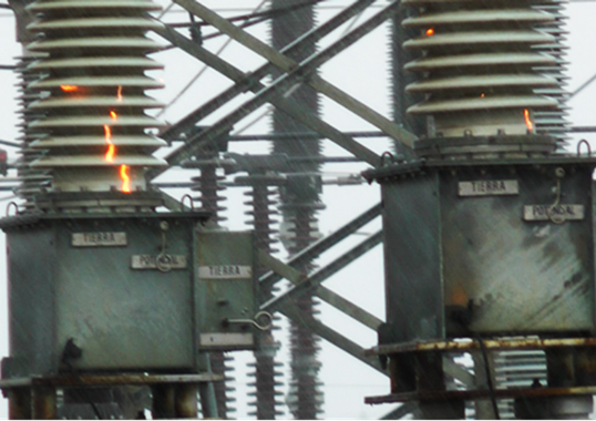
Most porcelain station posts still rely on relatively inexpensive stacking technology whereby posts having 1 to 2 m arcing distance are assembled to reach the total needed for EHV and UHV ranges. This solution has the greatest field experience, which confirms its reliability – especially from the mechanical standpoint. More advanced porcelain solutions have now also become available. These allow single post insulators up to several meters in height, thereby removing the need for intermediate flanges, and with optimized profiles that offer reduced shed thickness and tip radius.
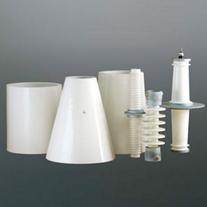
The hollow core composite solution, having hydrophobicity transfer material (HTM) characteristics, also permits single post insulators of the required length and without flanges and offers additional advantages such as lower weight and superior performance under pollution and seismic conditions. But these must be specifically designed to comply with all mechanical requirements, such as minimizing deflection at the top in the case of disconnector applications. The hybrid solution, based on a porcelain core and an HTM silicone housing, shares the advantages and disadvantages of the other solutions. One of the drawbacks of these newer solutions is higher cost versus traditional stacked porcelain technology, where a highly competitive supply situation keeps pressure on prices.
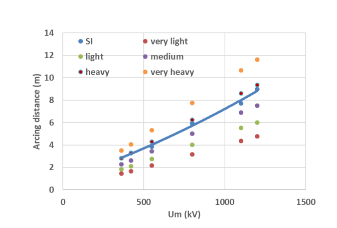

For AC applications, Fig. 1 compares requirements under switching impulse in rainy conditions (SI wet) and under pollution, referring to the most critical application configuration such as for disconnectors in the open position or at the busbar termination side. This chart indicates that SI dominates design up to heavy contamination conditions – even when using traditional porcelain multi-stack solutions with relatively low creepage factor – and will continue to dominate design even at high pollution levels (assuming suitable porcelain profiles will be selected within the range foreseen in IEC 60815-2). As such, marginal design optimization with maximum arcing distance gains of from 10 to 20% can only be obtained by optimizing insulator SI performance under rain, e.g. by reducing insulator diameter, number of flanges and selecting insulators with HTM housing and optimized design. Here, due to marginal allowable design optimization and resulting marginal cost reduction, greater adoption of the latest station post technologies can only be expected if there is a dramatic reduction in their acquisition costs.
![]()

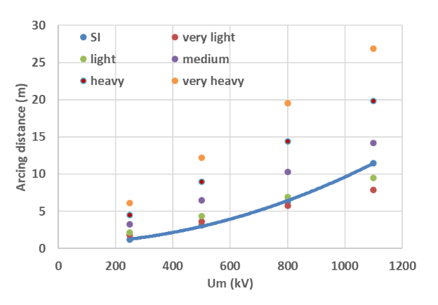
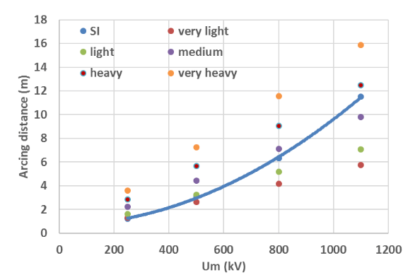
For DC applications, Figs. 2 and 3 compare the requirements under switching impulse in rainy conditions (SI wet) with pollution. This evaluation was made based on an SI level of 2 p.u. with respect to system voltage. Pollution requirements are derived from IEC Technical Specification 60815-4 and by extrapolating to DC the pollution classes defined for AC. These figures indicate that pollution dominates design in the case of porcelain insulation, even when considering high creepage factors that are difficult to reach. Moreover, extreme heights could be necessary with porcelain insulators, making this solution impractical or even impossible – especially for heavy pollution and high system voltage. More reasonable heights would be required for hybrid and composite solutions, the latter being preferable in case of strict seismic requirements. Post type insulators with HTM properties therefore offer the best solution for HVDC applications and their future development will depend largely on the pace of expansion of such systems worldwide.