This edited past contribution to INMR by Giovanni Giobbe of Gruppo Bonomi/EB Rebosio in Italy reviewed the benefits and applications of interphase spacers on overhead lines to counteract risks due to icing and wind.
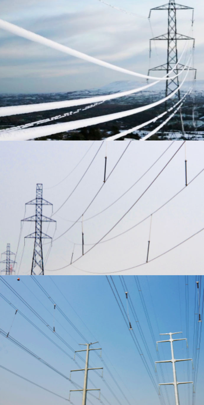
A phase spacer functions to prevent approach between phases of a high voltage overhead circuit in the presence of ice sleeves and/or strong wind that can cause increased deflection of conductors due to greater mechanical loading. Different scenarios are possible during generation of an ice sleeve. For example, the ice sleeve deposited on a lower phase can disperse suddenly, while that deposited on an upper phase remains unchanged. Under such sudden shedding, an oscillation or whiplash is triggered on the lower phase, which brings it dangerously close to the upper phase still fitted with the ice sleeve. This phenomenon, known as jumping, could generate electrical discharge between the phases. The ice sleeve deposited on a lower phase can also gradually disperse while that on the upper phase remains unchanged. Again, the two phases risk being brought too close together.
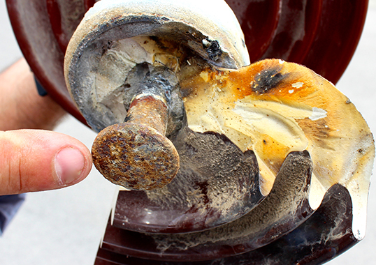
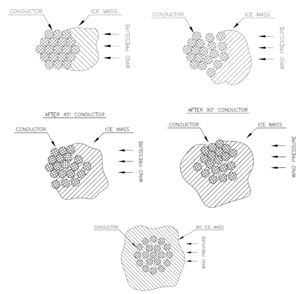
If wind and ice occur simultaneously, such as during an ‘ice storm’, with wind blowing sideways to the direction of a line, rotational conductor movement can occur. This tends to open strands, with consequent permanent deformation of the conductor together with a notable increase in weight that impacts both insulators and structures (see Fig. 1). In the most serious case, accumulation of snow on only one side of the conductor will cause rotation of strands due to the non-uniform weight on the conductor’s external surface and lead to possible tower collapse. Application of phase spacers in such situations can help counteract such rotation and relative opening of the conductor due to the contact clamps that hold strands in place (see Fig. 2).

A composite phase spacer differs from a typical composite insulator due to its much greater length. Moreover, its end-fittings are contact clamps that must be sized according to the diameter of the line’s phase conductors, to their relative position (simple, twin conductor, bundle, etc.) and to whether or not armour rods are mounted between conductor and clamp. Phase spacers can be adjustable for application on lines that have different distances between phases or with fixed insulation length, for lines with constant distance between phases.
Electrical & Mechanical Characteristics
Electrical characteristics of a phase spacer are different from those of a corresponding insulator since it is mounted between two phases and therefore subject to a system’s phase-to-phase voltage rather than phase-to-earth. The electrical characteristics that a phase spacer must comply with do not normally present a challenge because the length that it must have to connect two phases is typically much greater than needed to respect electrical values.
Mechanical sizing of a phase spacer must always include a guaranteed tensile load (STL or SML) as well as a guaranteed mechanical compression load (SCoL). Mechanical stresses on this device are both traction and compression in equal measure. Moreover, to guarantee non-deformability of a phase spacer, given its length that is linked to the distance between phases, it is necessary to size the internal FRP rod such that the spacer does not flex excessively under its own weight or under application of mechanical compression. Therefore, diameter of the core rod of a spacer is typically greater than for a corresponding composite insulator. Taking these considerations into account, the electrical and mechanical sizing of a phase spacer, while similar, is not the same as for a composite line insulator. In general, greater attention must be paid to diameter of the FRP rod and its relative length so that the spacer can withstand traction as well as compression and does not deform excessively under application of these loads.
The raw materials used to manufacture phase spacers are basically the same as for most composite insulators, i.e. FRP core rod, hot-galvanized steel end-fittings and HTV silicone for the external housing. Since dimensions are so important, it is difficult to mold the silicone housing onto the rod in a single step and two or more molding cycles are generally required. In addition, extra care must be taken when packing spacers for shipment, whether in wooden crates or in water repellent tubes.
Table 1 shows the mechanical characteristics of several types of phase spacers suitable for application on 400 kV overhead lines.
Fig. 3 shows the dimensions and characteristics of a phase spacer design from EB Rebosio, conforming to those shown for Type 5 in Table 1.

Installation
There are two main types of spacer installation configurations, Schemes A and B. The former is more suitable for lines with rated voltages of 150 kV, 220 kV or 400 kV and with maximum span between structures of 500 m. Scheme B, by contrast, applies more for lines with nominal voltage of 400 kV and distance between structures greater than 500 m.
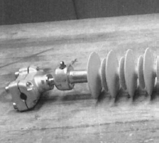
![]() Phase spacers are mounted onto the conductor of underlying phases using an appropriate end-fitting design. End fittings can also be equipped with armour rods to help dampen vibrations generated on the conductor under strong wind or sudden drop of the accreted ice sleeve.
Phase spacers are mounted onto the conductor of underlying phases using an appropriate end-fitting design. End fittings can also be equipped with armour rods to help dampen vibrations generated on the conductor under strong wind or sudden drop of the accreted ice sleeve.

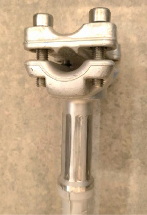
While different types of clamps are used in design of phase spacers, their common purpose is to hold the phase conductors on each side. In this regard, the end-fittings and specific connection clamps used are always the same and symmetrical at all high voltages. Below are examples of different clamps used to connect phase conductors using composite phase spacers.
While end-fittings on phase spacers can be constructed in a variety of ways, all must safely and securely join the connection clamps to the body of the phase spacer while resisting all applied traction or compression forces. Solutions adopted in this regard include clevis and tongue type end-fittings but it is also possible to use socket and ball end-fittings. In the latter case, it is necessary to also use additional connection clamps to allow assembly of the conductor’s holding clamp to the composite phase spacer. Below are examples of end-fittings mounted on 132 kV/150 kV/220 kV and 400 kV phase spacers.
International standards employed for sizing end-fittings for phase spacers are the same as used to size end-fittings of composite insulators, including IEC 61466-1 and IEC 61466-2. Regarding electrical performance of phase spacers, this is basically the same as required for composite insulators, apart from higher test values (i.e. the test values of insulators multiplied by √3). Spacers must therefore always be tested at a voltage that simulates the long-term effects of application at phase-to-phase voltage. This also applies for calculation of minimum required leakage distance that must be based on actual phase-to-phase voltage. The electrical tests to which phase spacers are subject are the same as for line insulators, namely:
• Dry lightning impulse withstand or flashover voltage test;
• Wet power frequency withstand or flashover voltage test;
• Wet switching impulse withstand or flashover voltage test.
In this case, electrical nameplate (seal) values prescribed by standards such as IEC 60071-1 must be multiplied by √3.
Checks, Tests & Inspection
The same requirements and checks are required for composite phase spacers as apply for insulators made of composite materials. The specific standards to be applied to design, type, acceptance and individual routine tests are IEC 60815-3, 62217, 61109 and 60437. Using IEC 60815-3 allows obtaining the dimensional parameters, spacing and, more generally, the shape of the external silicone housing as a function of level of contamination along the path of the overhead line (with specific leakage distance expressed in mm/kV but calculated using the concatenated voltage). IEC 62217 and 61109 are used as a reference when performing all design tests, such as testing interfaces and connections, tests on the housing and on the internal FRP rod as well as tracking and erosion tests and long-term mechanical checks.
IEC 60437 is the reference standard if it is necessary to verify level of radio influence voltage (i.e. an RIV test) or ignition and extinction voltage linked to corona and, more generally, to account for distribution of electric field along the interphase spacer. Type tests such as verification of sealing salinity (ref. IEC 60507) or power arc tests (ref. IEC 61467) are not normally needed to verify behaviour of interphase spacers. These tests more link to behaviour of suspension and tension insulators once connected to the metal end-fittings connecting to the tower support and to the phase conductor.
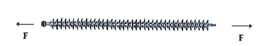
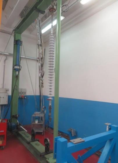
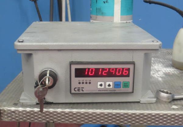
A significant type test to verify behaviour of the composite insulators in interphase spacers relates to mechanical tensile stress. In Italy, for example, this is performed on composite insulators used on all high voltage lines and consists of applying an axial traction force to the insulator. The force (F) consists of a component with an alternating sinusoidal pattern superimposed on a constant component equal to 22% of Specified Mechanical Load of the insulator under test (i.e. the SML according to IEC 61109). The alternating component must always have a peak value equal to 8% of the insulator’s SML. Moreover, frequency of the alternating component must be between 0.5 and 5 Hz and number of test cycles must equal 1 million. The test is considered passed if, at the end of these cycles, visual inspection reveals no evidence of damage to the housing or to end-fittings. This test therefore simulates, as closely as possible, the mechanical stresses to which a spacer will be subjected during its service life.
In regard to testing and acceptance tests before delivery of a batch of spacers to the end customer, the applicable reference standard is paragraph 12 of IEC 61109. Number of samples to be tested is based on number of spacers in the batch being shipped and tests to be performed on these, defined in detail, include: dimensional checks, mechanical checks and verification of other parameters essential for satisfactory long-term service performance. The description of each test contains the procedure as well as relative acceptance criteria according to results obtained.

Other Types of Spacers
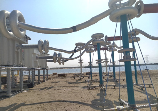
Apart from application on overhead lines subject to icing of conductors, interphase spacers can also be mounted in service areas exposed to sudden strong winds, such as deserts. In this case, mounting spacers between the phases of the line helps limit the phenomenon of conductor galloping, generated for example by intense winds during sandstorms.
The interphase spacers used in this application often utilize aluminium end-fittings to attach to phase conductors because the mechanical loads involved, both traction and compression, are lower than those required for composite line insulators having the same electrical characteristics. Using end-fittings made of aluminium results in reduced spacer weight on the line and also facilitates installation.

Conclusions
Interphase spacers are applied to maintain constant distance between phases of an overhead line. The most frequent situations where these find application are where a line is exposed to strong winds and snowstorms that can generate ice sleeves on conductors. Spacers help avoid the phenomenon of jumping and are also able to dampen the galloping effect of conductors under high-speed winds.
Design of interphase spacers requires taking into consideration the particular conditions under which it is applied:
• the spacer works both in traction and in compression;
• the mechanical compression and traction loads to which a spacer is subjected are lower than those typical of composite line insulators;
• the diameter of the internal fiberglass rod of the spacer must be greater than that of a corresponding line insulator because it is much longer. It is therefore necessary to take special care to avoid damage or deformation during transport, handling and installation.
In regard tests and checks on spacers, electrical testing plays a far less important role than does mechanical testing. A tensile test with mechanical load with long-term sinusoidal behaviour must also be performed.

Bibliography
TERNA LIN_00000J20 Rev. 00 of the 27/07/2018
COMPOSITE INSULATORS FOR INTERPHASE SPACERS
TERNA LIN_00000J39 Rev. 00 of the 24/04/2013
INSTRUCTIONS FOR THE CONSTRUCTION, SUPPLY AND TESTING OF INSULATORS
COMPOSITES FOR OVERHEAD ELECTRICAL LINES VOLTAGE ≥ 132 kV
ENEL DISTRIBUTIE FISA TEHNICA FT-121_MAT Ed. 2 21.01.2016
DISTANTIER INTERFAZIC 110 kV
IEEE 2011 – CONFERENCE ZHANGIJAJIE, HUNAN, CHINA
EFFECT OF INTERPHASE COMPOSITE SPACER ON TRANSMISSION LINE GALOPPING CONTROL