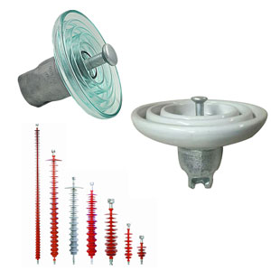
Bushings are key components of HV substation equipment such as transformers and switchgear, allowing conductors to transfer energy from one insulating medium to another. Most typically, this is from an oil or SF6 insulation environment to air. Bushings are also used in air-to-air applications such as wall bushings, oil-to-oil, oil-to-SF6, etc. Bushings can be internally insulated using a variety of technologies, including: oil-impregnated paper (by far the dominant type); resin bonded paper (an old technology that still finds selected applications, such as for generator bushings); resin-impregnated paper (an increasingly popular dry-type alternative to oil that can now be used even in UHV applications); or SF6 gas.
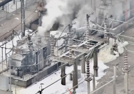
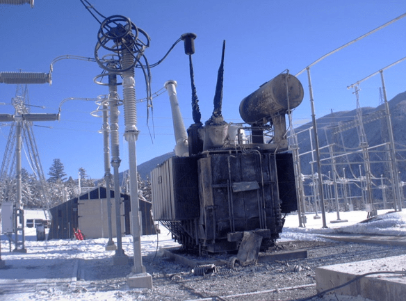
The cost of bushings, such as on a HV power transformer, generally accounts for only 5 to 8% of the total installed cost of the equipment. But bushing failure can prove catastrophic and result in loss of costly assets with potentially long replacement lead times. There are also issues relating to safety of personnel and damage of nearby equipment. To prevent failures, it is therefore important that bushings be periodically tested to detect, at an early stage, insulation breakdown due to ageing and other problems.
This edited past contribution to INMR by staff at the HV Laboratory at Powertech Labs in Canada, reviewed basics of testing bushings and also provided case histories where root cause of failure was investigated.


Field Testing versus Laboratory Testing
Aged bushings or bushings whose condition is suspect can be tested in the field or in a HV laboratory, whether independent or operated by the manufacturer. Testing in situ has the advantage that outage time can be minimized or even eliminated e.g. by using on-line monitoring systems. But a key constraint with in-service testing is that there is a limit to the variety of tests that can be performed. There is also a risk that early stage problems may not yet be evident. Moreover, in most cases such testing is limited to low voltage tests. Testing in a laboratory environment allows tests at voltages above rating so as to better detect incipient problems that cannot easily be identified in the field. A laboratory also allows more sophisticated equipment to be used and electrical interference to be eliminated. Of course, the downside is the outage time required and the cost of removing and shipping the bushing. As a result, under normal conditions most bushing testing still tends to be limited to in-service tests.

Bushing Test Methods
The most common testing done on bushings in the field involves measuring capacitance and dielectric loss at voltages up to 10 kV (i.e. Doble testing). There are also systems available that will do this measurement on-line at operating voltage. Thermography can also be used to look for internal overheating or at connections on the exposed portion of the bushing. Another diagnostic that can be done on-site is to take an oil sample for analysis. While some systems can now analyse oil on-site, most often the sample is sent to a special laboratory for testing, which includes looking for excess moisture or gases generated by partial discharge activity, overheating or internal arcing.
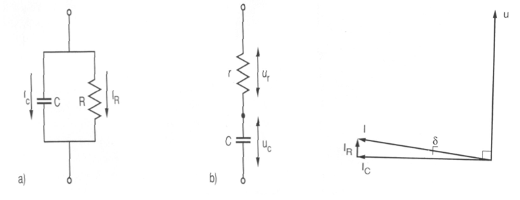
In a HV test laboratory, bushings typically undergo a series of tests, from capacitance and dissipation factor/tan delta tests/power factor tests to partial discharge tests to AC withstand tests and occasionally also impulse tests as well as oil testing. The dissipation factor – or power factor – of a bushing is the ratio of the resistive current component to the total leakage current under applied voltage. Generally speaking, a power factor of less than 1% for oil-impregnated paper (OIP) bushings is considered good, while 1% to 2% is regarded as questionable. A power factor that exceeds 2% requires prompt action.
In practice, evaluation is based not only on a single power factor data point but also on history of change in power factor. Fig. 1 graphically depicts what is involved in such measurements. Measured capacitance of the bushing should not increase more than 3% above nameplate data or factory test data since a higher value could indicate partial puncture.
Since partial discharge (PD) in a bushing degrades the properties of the insulating material and can lead to eventual failure, testing for PD is useful and normally done in the laboratory. In the case of OIP type bushings, for example, the PD at the test level should normally not exceed 10 pC. While PD can also be measured on bushings in-service, one problem is that background interference is normally too high. In a laboratory environment, it is possible to perform measurements on bushings with background levels <1 pC. As mentioned, testing the oil of an OIP bushing can be used to detect excess moisture or gases generated by problems such as partial discharge, overheating and internal arcing. This is not however normally carried out on a routine basis because bushings are usually factory sealed and tightness-tested at time of manufacture. Only when there is evidence of a potential problem, e.g. higher than normal power factor, will there be reason for oil sampling and analysis. In such cases, tests commonly evaluate concentration of hydrogen, methane, acetylene, ethylene, ethane, carbon monoxide, carbon dioxide, nitrogen and oxygen. The relative ratios and concentrations of these gases in each oil sample are then used to identify problems with insulation structure.
Laboratory Testing
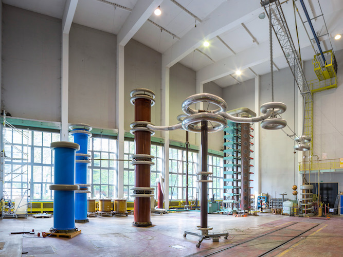
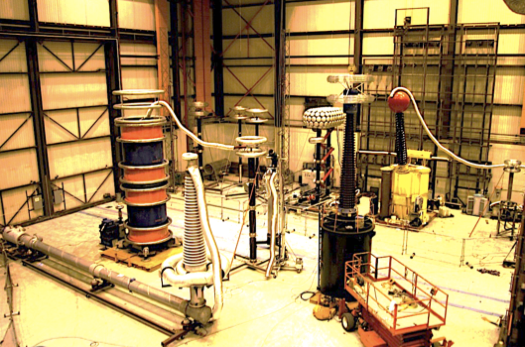
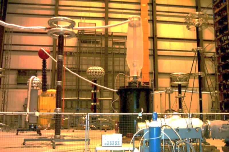
Testing a bushing in a HV laboratory requires that it be set-up to simulate its operating environment. In the case of oil-insulated power transformer bushings, this means that the lower end of the bushing must be immersed in oil. Powertech Labs, for example, tests bushings rated up to 500 kV in an oil-filled tank that originally housed a 500 kV reactor. Unique and clever test arrangements often need to be devised so as to be able to energize a bushing for testing without having it flashover. One such set-up involved a 500 kV SF6-to-oil bushing used to connect an SF6 bus to a generator transformer. The lower end was submerged in oil, as it would be in service, but there was no conventional hardware available to put the upper end in a pressurized SF6 atmosphere. Instead the HV conductor was extended about 4.6 meters using a 0.3 m pipe. The pipe and upper bushing section were then enclosed in a plastic bag, later filled with SF6 to maximize the external withstand capability of the bushing’s SF6 end.

Test Procedure
In general, the procedure used at Powertech Labs to test bushings removed from service is as follows:
• oil sample taken for gas-in-oil analysis;
• bushing capacitance and dissipation factor measured at low voltage and at rated voltage;
• applied voltage raised to 80% of rated withstand level (e.g. 656 kV for 500 kV bushings) and held for one minute. Partial discharge inception voltage measured;
• voltage lowered to PD extinction which must be >110% of rated line-to-ground voltage;
• partial discharge at 110% maximum operating voltage must be <12 pC (e.g. for 500 kV bushings: 1.1 * 500/Ö3=318 kV);
• bushing capacitance and dissipation factor measurements repeated;
• oil sample taken again for gas-oil analysis.
Powertech Labs has tested many suspect OIP bushings removed from service for reasons including failures of similar bushings, high gas-in-oil levels, etc. The voltage rating of bushings tested ranged from 69 kV floor bushings to 230 kV transformer bushings to 500 kV transformer/reactor bushings. The oldest was manufactured in 1967 and several manufacturers have been involved. Tested bushings have demonstrated the following pass/failure rates:
• 500 kV (28 bushings in total): Failure rate of 25%
• 230 kV (4 units): Failure rate of 50%
• 69 kV (11 units): Failure rate of 72%
Causes of failures included high partial discharge activity, high dissipation factor and high gas-in-oil test results, with the majority due to partial discharges that exceeded specified test level.

Selected Case Histories
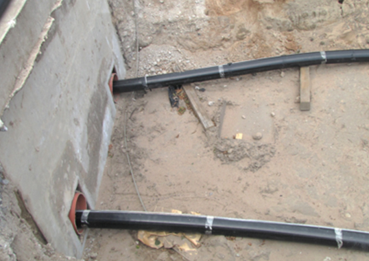
Failure of 69 kV Floor Bushing
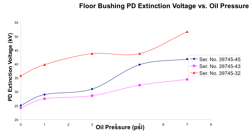
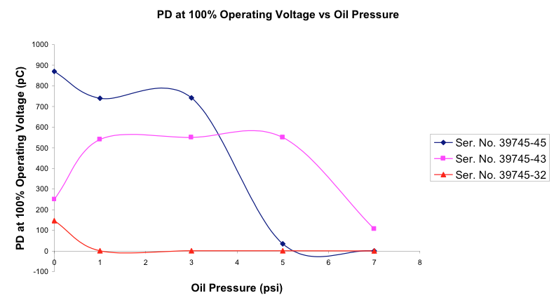
BC Hydro, the major electricity provider in British Columbia, had suspect 69 kV floor air-to-air bushings in service at an indoor multi-story substation. Audible partial discharges had been detected on these bushings and this triggered further investigation. In-service ultrasonic acoustic testing was done and it was found the high partial discharge activity was not present at all times. It was suspected that, since the bushings heated up, increased internal pressure would cause the voids to disappear and partial discharges to stop. To verify this, three of the bushings were tested at different internal pressures and this confirmed that partial discharge was indeed affected by internal pressure (see Fig. 2 and 3). As pressure increased, partial discharges would stop. This explained why acoustic partial discharge activity from these bushings was detected only intermittently. When the bushings heated up due to load current, internal pressure would increase and partial discharges would stop. Then, when load dropped and bushing temperature decreased, the partial discharges would return.

Hydrogen Level in 500 kV OIP Bushings
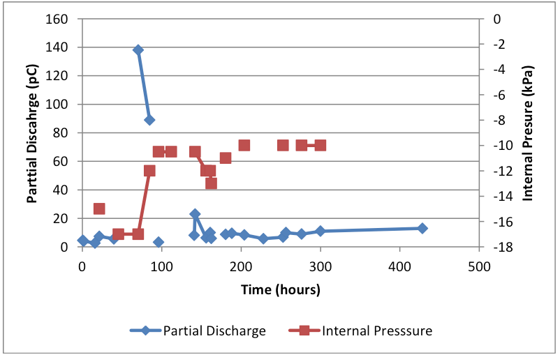
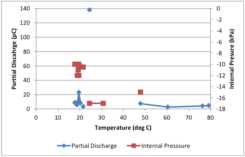
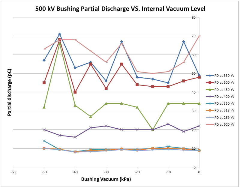
In 2012, a 500 kV bushing failure occurred on a substation transformer. Subsequent investigation found that a number of the 500 kV bushings at this substation had high hydrogen levels in their oil, normally indicative of internal partial discharge activity. Since these particular bushings had been subject to wide service temperature fluctuations, it was suspected that an internal vacuum would develop in the bushing during cold temperatures. This caused gas bubbles to develop that could lead to internal partial discharges, generation of hydrogen and ultimately to bushing failure. One of the bushings was removed and sent for laboratory testing where it was first subjected to the standard test procedure, as discussed above. The gas in oil tests found a hydrogen level of 976 ppm (versus a normal limit of 100 ppm) but with no other significant combustible gases. Still, in spite of the high hydrogen level, the bushing passed all dielectric tests, including the partial discharge test (<12 pC). Since it was not possible to cool the bushing in the laboratory, to simulate the effect of low temperatures, the bushing was placed in a bushing test tank. The oil in the tank was then circulated through a mini-oil treatment plant to heat it and therefore the bushing as well. During heating, the top fill oil port on the bushing was left open. Insulating blankets were then placed on the oil tank and the bushing to minimize heat loss. The idea was to heat the bushing as much as possible to a maximum of 95°C. Once the maximum bushing temperature was reached (i.e. after about 4 days of heating), the bushing was topped up with hot oil so that the volume of the headspace was at a minimum. A valve and vacuum gauge were installed and the valve was closed thus sealing the bushing at maximum temperature. Then, as the oil cooled, vacuum would develop inside the bushing. The partial discharge, capacitance and tan delta were all measured both with the bushing hot and as the bushing cooled. Fig. 4 shows the partial discharge, bushing internal pressure vs. time and Fig. 5 depicts the bushing PD and internal pressure vs. temperature (at 318 kV - maximum operating voltage). There was a distinct increase in partial discharge at 318 kV – in this case up to 138 pC – for a short period as the bushing cooled. This showed that, under the right circumstances, pressure reduction in the bushing could cause internal partial discharge at operating voltage and produce hydrogen. After the bushing cooled completely, the internal vacuum was released. It was then suggested that, instead of heating and cooling to simulate field conditions, the same could be achieved by drawing a vacuum on the bushing. To test this, the bushing was vacuumed to pressures from -5 to -50 kPa and Fig. 6 shows the bushing’s partial discharge vs. internal pressure at various voltages. It is clear that, at operating voltage, there was no significant partial discharge. The effect of pressure was observed only at -45 kPa and at voltages above 400 kV. Subsequent to these tests, the bushing’s internal pressure was left at -15 kPa and it was energized over several weeks at gradually increasing voltages up to 600 kV. There was no increase in partial discharge observed over this period and hydrogen level decreased.
Such testing demonstrated that the bushing could be producing hydrogen in service due to partial discharge under cold conditions. Energizing the bushing at overvoltage conditions for extended periods did not cause failure. This provided evidence that, even though there was significant hydrogen in the bushings, they did not show permanent damage. If generation of vacuum in these bushings could be prevented, production of hydrogen would stop and they could safely be kept in service.

Conclusions
With ageing of power systems, problems related to bushing insulation are becoming increasingly common. Experience at Powertech Labs with high failure rates on those bushings being tested has confirmed this. Testing bushings in-service can uncover developing problems before these result in costly problems and outages. However, in many cases, to best determine the extent of and cause of problems, laboratory testing may be required. While it is expensive to remove bushings and have them tested in a laboratory, this process can successfully ‘weed out’ those at high risk. Given the high impact of catastrophic bushing failure, this can be cost-justified.