The Appalachian Power Region of American Electric Power’s (AEP’s) service territory includes substations that have autotransformers with ungrounded delta tertiary windings. In some cases, tertiary windings are used strictly for AC service power inside the substation. In other cases, they serve as sources for a local sub-transmission system that includes a number of other substations in the region. Either way, grounding transformers are commonly used to be able to detect line-to-ground faults and stabilize the neutral during system unbalance situations such as fault conditions. Given the complex nature of ungrounded sub-transmission systems with grounding transformers, sizing considerations for surge arresters are important.
This edited past contribution to INMR by Xuan Wu, Ben Leece, Ron Wellman, Ken Pose of AEP reviewed their surge arrester sizing methodology for ungrounded sub-transmission systems with grounding banks with specific focus on varying transient overvoltage (TOV) conditions
System Considerations
A sub-transmission system is considered ‘effectively grounded’ at a particular location if the ratio between its zero-sequence reactance (X0) and its positive-sequence reactance (X1) satisfies 0<X0/X1< 3. A grounding transformer would lower the overall zero-sequence impedance of the power system at the grounding transformer location X0 to a desired value. Assume that X1=X2 (negative-sequence reactance) and R1 (positive-sequence resistance) = R2 (negative-sequence resistance) = R0 (zero-sequence resistance) = 0. Therefore, for X0/X1 = 1, voltage on the unfaulted phases remains at 1.0 p.u.; for X0/X1=3, voltage on the unfaulted phases increases to 1.26 p.u.; for X0/X1=5, voltage increases to 1.38 p.u.
The above voltage values would take place at the location where the line-to-ground fault occurs and where a grounding transformer is installed. The voltage on unfaulted phases at locations away from the fault and away from the grounding transformer location would be higher. Lowering the X0/X1 ratio at a particular system location will result in higher line-to-ground fault current at that location. Higher fault current allows for improved relay protection coordination with downstream protective equipment. However, even though grounding transformers improve relay protection coordination, decisions regarding installing grounding transformers and selecting their impedance to increase line-to-ground fault current at a particular location should be evaluated case-by-case.

Surge Arrester Selection & Location
Surge arresters should be placed for protection of station equipment, including transformers, reactors, capacitor banks, circuit breakers, underground power cables, etc.
In order to select and apply the appropriate surge arrester to protect corresponding equipment, the following steps need to be considered. Note that the focus here is on Temporary Overvoltage (TOV) evaluation, which governs the selection process for surge arresters used on ungrounded sub-transmission systems. Additionally, determination of separation distance (Step 2) is concentrated as well. Steps 3 & 4 are relatively straightforward and not discussed in detail.
Step 1: Select Surge Arrester
1. MCOV ≥ maximum continuous line-to-ground voltage;
2. TOV capability ≥ system TOV;
3. Pressure relief/short-circuit current discharge capability ≥ system line-to-ground fault rms current magnitude.
Step 2: Locate Surge Arrester
1. A surge arrester shall be located as close as possible to the equipment to be protected;
2. Otherwise, calculation is needed to determine maximum allowable separation distance between the equipment to be protected and the arrester. If so, Step 4 can be bypassed.
Step 3: Evaluate Insulation Co-ordination
1. Gather surge arrester protective levels, including lightning impulse protective level (LPL), front-of-wave protective level (FOW) and switching impulse protective level (SPL);
2. Gather equipment insulation levels, including basic lightning impulse insulation level (BIL), chopped wave withstand (CWW) and basic switching impulse insulation level (BSL);
3. If effect of separation distance can be disregarded, the protective ratios for lightning, PRL1 and PRL2, and switching impulses PRS are:
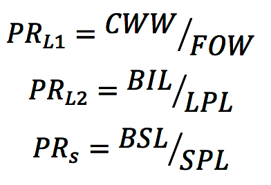
For acceptable coordination, PRL1 and PRL2 should be equal to or greater than 1.2 and PRS should be equal to or greater than 1.15.
Step 4: Evaluate Alternates
If acceptable coordination cannot be achieved, evaluate the following measures:
1. Increasing BIL and BSL;
2. Decreasing arrester separation distance;
3. Adding additional arresters;
4. Using arrester with lower protective characteristics.

Surge Arrester Selection
Maximum Continuous Operating Voltage (MCOV)
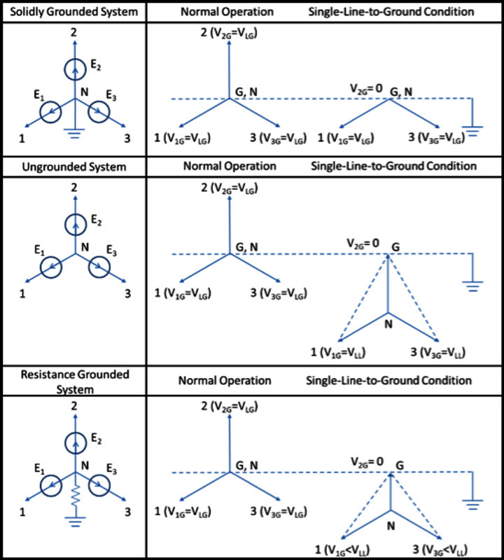
Select a surge arrester MCOV rating equivalent to or greater than the maximum steady-state line-to-ground system voltage at the arrester location. Note that some systems, e.g. supplied from an ungrounded source with no grounding transformer or from a wye-grounded transformer with a neutral grounding resistor (NGR) and which are supposed to be operated continuously after a single line-to-ground event, need to use arresters with MCOV rated line-to-line voltages. As shown in Fig. 4, a line-to-ground fault occurring on a solidly grounded system results in the voltage between the faulted phase and the neutral collapsing to zero. However, if the neutral is ungrounded (as in the second row), the voltage between the faulted phase and the neutral is retained as the line-to-ground voltage while the faulted phase is at a zero potential. As a result, the neutral-to-ground voltage is shifted from zero to the system line-to-ground voltage and the line-to-ground voltages of the unfaulted phases become the system line-to-line voltages. If an NGR is installed, the neutral-to-ground voltage during a line-to-ground fault condition is between zero and system line-to-ground voltage.
Note that if a grounding transformer is possibly isolated from the tertiary winding (such as illustrated in Fig. 5) while the autotransformer is still energized, MCOV rating of the corresponding surge arrester needs to be sized to the line-to-line voltage.
Maximum Temporary Overvoltage (TOV)
In addition to considerations affecting selection of arrester MCOV, it is also necessary to select the arrester to be able to withstand the temporary system overvoltage at the arrester’s location. The basic requirement is that the TOV capability of the arrester should be higher than the TOV amplitude versus duration characteristic of the system during all times of concern.
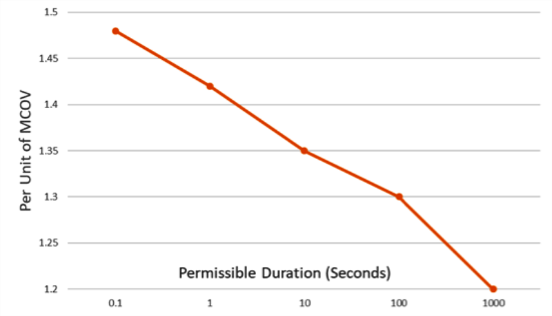
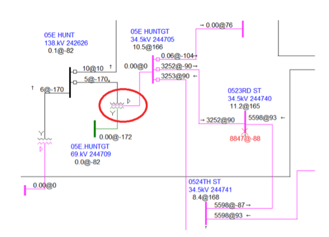
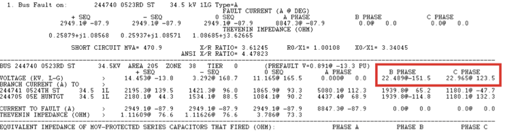
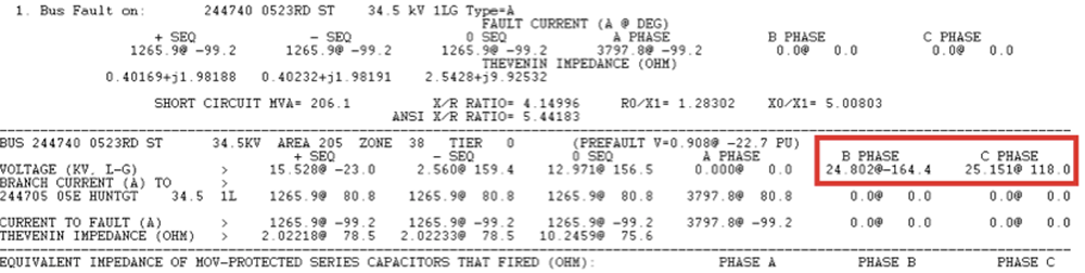
Fig. 6 shows an example TOV curve for station-class arresters, shown for illustrative purposes only. TOV data for applications should be obtained from the manufacturer. Back-up fault clearing time is the TOV duration, which should be acquired from the corresponding Protection & Controls (P&C) Engineer. Note that back-up fault clearing time is calculated considering a single equipment failure (e.g. breaker / relay / communication failure). The arrester selected should have both MCOV and TOV capability appropriate for the operating system. Sometimes the MCOV is decisive while other times TOV considerations are decisive. A change in relay setting or use of faster breakers may sometimes allow use of arresters based on MCOV when TOV would otherwise have been decisive. Note that TOV considerations govern the arrester selections of ungrounded sub-transmission systems. The most common source of TOV is voltage rise on unfaulted phases during a line-to-ground fault. This voltage rise becomes more severe when the system is more ungrounded. The extreme case is a pure delta or ungrounded wye system, which has 1.73 p.u. overvoltages on unfaulted phases during a line-to-ground fault (referring to Fig. 4). In AEP sub-transmission systems (23~46 kV voltage classes), there are a number of circuits which are not solidly grounded (between 1.0 and 1.73 p.u.), which are required to be analyzed using ASPEN. Fig. 7 shows an example that the 34.5 kV 23rd Street bus is connected to a delta tertiary highlighted in the red circle. The overvoltage on phase C of this bus during a line-to-ground fault on phase A is 22.965/19.94=1.15 p.u. based on the ASPEN output in Fig. 8. If the line between 23rd and 24th Street buses is out of service as a contingency, the previous overvoltage is increased to 25.151/19.94=1.26 p.u. based on the ASPEN output in Fig. 9. Both of these overvoltages should be considered as well as the backup clearing time with the selected surge arrester’s TOV curve.
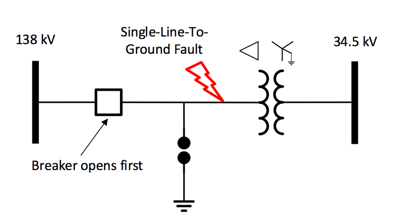
Another source of TOV is a backfeed from a delta-connected transformer winding when it is disconnected from a grounded system. Consider for example, a 138/34.5 kV transformer connected delta and wye-grounded on the 138 kV and 34.5 kV, respectively. The 138 kV side is connected to a 138 kV wye-grounded system. However, the 138 kV transformer winding will be disconnected from the 138 kV grounded system for 138 kV line-to-ground faults, thus leaving the 138 kV winding ungrounded and energized from the 34.5 kV source until that source is disconnected. In this case, the TOV on the unfaulted phases will rise to 145 kV (1.73 × maximum line-ground voltage).
Pressure Relief/Short-Circuit Current Discharge Capability
The arrester class determines the energy discharge capability of the arrester blocks and the pressure relief capability, expressed in kA RMS, of the arrester housing. The pressure relief capability of the arrester housing is necessary to be equal to or higher than the maximum line-to-ground symmetrical fault current at the arrester location. If the pressure relief capability is insufficient to handle the expected fault current at that location, then an additional arrester may need to be connected in parallel.

Locate Surge Arresters
Surge arresters are recommended to be installed as close as possible to the equipment to be protected. The protective margin provided by the arrester to the equipment it protects decreases as the separation distance between the arrester and the equipment increases. The reason for the reduced protection is that the remaining surge after being clamped by an arrester travels and hits a shunt equipment, such as a transformer winding, and then is reflected, which can result in voltage doubling if the separation distance is long enough. In most cases, the reflected voltage only adds a few percent to the incoming surge. It is this traveling wave phenomenon and its associated reflection that create the separate distance issue.
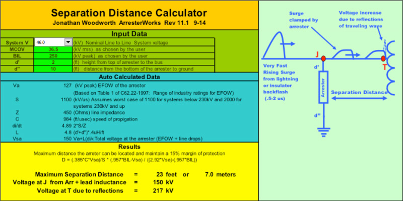
The calculator discussed in Fig. 11, developed by consultant Jonathan Woodworth, is based on the formula found in Annex C of IEEE Std. C62.22. It also incorporates tables from typical arrester characteristics. Once all relevant parameters are entered in the green boxes, the maximum separation distance is calculated and shown in the yellow area with 23 feet or 7.0 m for this specific example. This calculator is used to calculate the separation distances for various sub-transmission system voltages.

Selected Surge Arrester Parameters
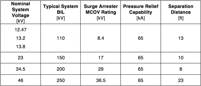
After considering all the steps discussed above, Table 1 shows the selected surge arrester parameters for various AEP sub-transmission systems according to AEP system BIL values and worst-case TOV behaviors. Note that AEP is able to ensure that all line-to-ground faults are cleared within 10 seconds when at least one grounding transformer is connected to the corresponding network. Note also that the separation distance is calculated using the Separation Distance Calculator using the associated system BIL and selected arrester MCOV values from Table 1.
Summary
Sub-transmission systems are often sourced from ungrounded delta autotransformer tertiaries. Typically, grounding transformers are used to provide a grounding reference for these ungrounded sources. However, these systems are not solidly grounded even with grounding transformers, which can be shown by the system X0/X1 ratio. This also indicates that the unfaulted phases during a single-line-to-ground fault will have overvoltage between 1.0 to 1.73 p.u. over the fault clearing time. This TOV evaluation governs selection of surge arresters for the sub-transmission system. Note that if it is possible to isolate the grounding transformer from the surge arrester while still energized, the elevated MCOV rating is necessary. Finally, separation distance needs to be considered based on the selected surge arrester protective and the equipment insulation levels.
References
[1] IEEE Std. C62.92.1, IEEE Guide for the Application of Neutral Grounding in Electrical Utility Systems—Part I: Introduction, 2016 Edition.
[2] IEEE Std. C62.22, IEEE Guide for the Application of Metal-Oxide Surge Arresters for Alternating-Current Systems, 2009 Edition.
[3] ASPEN OneLiner Software, Advanced Systems for Power Engineering, Inc. (ASPEN), San Mateo, CA 94401 U.S.A., 2018.
[4] Jonathan Woodworth, Separation Distance Calculator, ArresterWorks, 2014.