Past technical recommendations such as IEC/TR 60815 as well as newer specifications such as IEC/TS 60815 are both used by power utilities for insulator selection in polluted outdoor environments.
This edited contribution to INMR by Dr. Wallace Vosloo, retired from Eskom, Richardo Davey of Eskom Research Testing and Johannes Bekker at the University of Stellenbosch in South Africa reviewed different possible approaches in this regard.
Using IEC/TR 60815
Selecting porcelain and glass insulators for three-phase a.c. systems up to 525 kV phase-to-phase using IEC/TR 60815 (Guide for the selection of insulators in respect of polluted conditions) has been based on service experience as well as laboratory testing under naturally and artificially polluted conditions. As stated in this document: Simple general rules should assist choosing the insulator, which should give satisfactory performance under polluted conditions.
Although it is advised to determine pollution type and severity and then use laboratory tests to help select insulators, many utilities have instead simply chosen to standardize on one or more values of minimum Specific Creepage Distance. Here, SCD (the ratio of the leakage distance measured between phase and earth over the r.m.s. phase to phase value of the highest voltage for the equipment) is recommended for various pollution levels (I to IV), namely 16, 20, 25 and 31 mm/kV(Um) respectively for Light, Medium, Heavy and Very Heavy pollution environments. Pollution levels I to IV are determined mainly from IEC/TR 60815 Tables (shown in Fig. 1), service experience or by doing site pollution severity (SPS) measurements using Equivalent Salt Deposit Density (ESDD) or Directional Dust Deposit Gauges (DDDG) methods. Table 1 shows typical ESDD and DDDG values used to classify site pollution level and minimum required SCD.
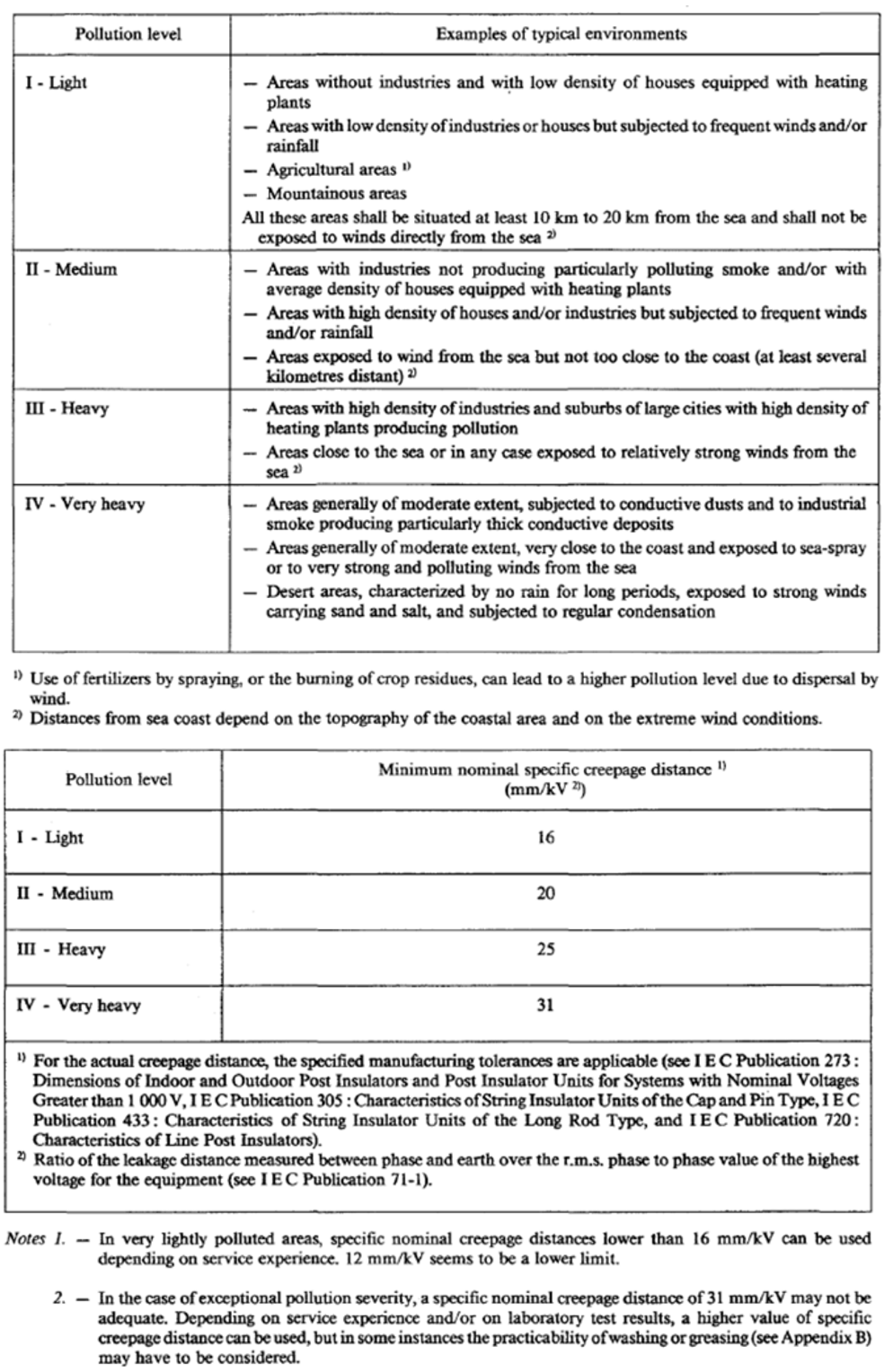
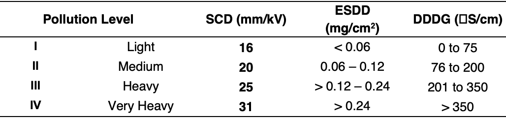

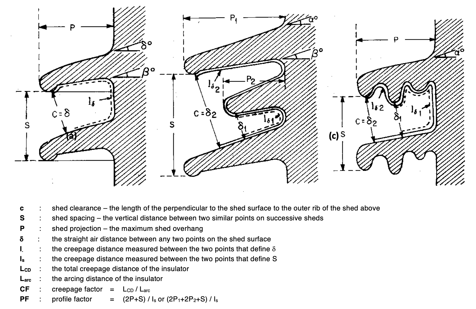
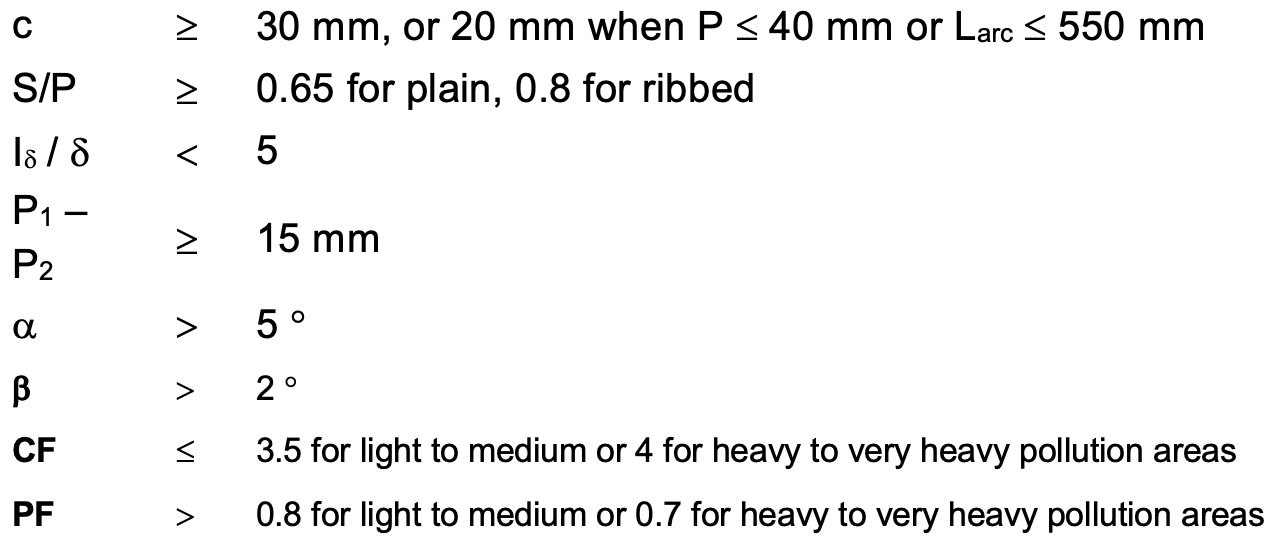
Fig. 2 and Table 2 summarize basic profiling rules recommended in IEC/TR 60815, which are normally followed.
Influence of insulator diameter on pollution performance is also considered for insulators with average diameters of between 300 and 500 mm. In the case of diameters greater than 500 mm, it is recommended that specific creepage distances be increased by 10% and 20%. Laboratory tests, in accordance with IEC 507, are also recommended to evaluate an insulator’s pollution performance but are rarely used by most power utilities. Greasing or washing is recommended for areas with severe pollution and/or low natural washing.
For a.c. porcelain and glass insulators, a utility would typically specify maximum connection length taking into account live line work, minimum dry arcing distance, and minimum creepage distance. Then, it would be stated that insulator profile must comply with IEC/TR 60815, the focus being on simplicity and ease of use.

Case Study Using IEC/TR 60815 for Selecting Insulators
It is proposed to erect 132 kV lines in areas with pollution levels ranging from Light to Very Heavy using standard glass cap & pin disc insulators (U120B, F12/146). Assuming the parameters given below, how many discs (n) would be required per string?
System highest voltage (Um) = 145 kV
Minimum required Dry Arcing Distance (DAD) of the insulator string is 1500 mm (i.e. for a high lightning area)
Disc spacing (s) = 146 mm
Arcing distance per disc (a) = 210 mm
Creepage distance (CD) per disc = 320 mm
The arcing distance of a disc insulator string = a + (n – 1) s
Thus, 1500 = 210 + (n – 1) x 146 and n = (1500 – 210) / 146 + 1 = 9.84 (in other words, 10 discs are required)
In terms of pollution level, as shown in Table 1, the specific creepage distances needed for Light, Medium, Heavy and Very Heavy pollution areas are 16, 20, 25 and 31 mm/kV (Um) respectively.
Number of discs required per string = (CD)/320 where CD = (Um x SCD)
Table 3 gives values calculated using (145 x SCD)/320.
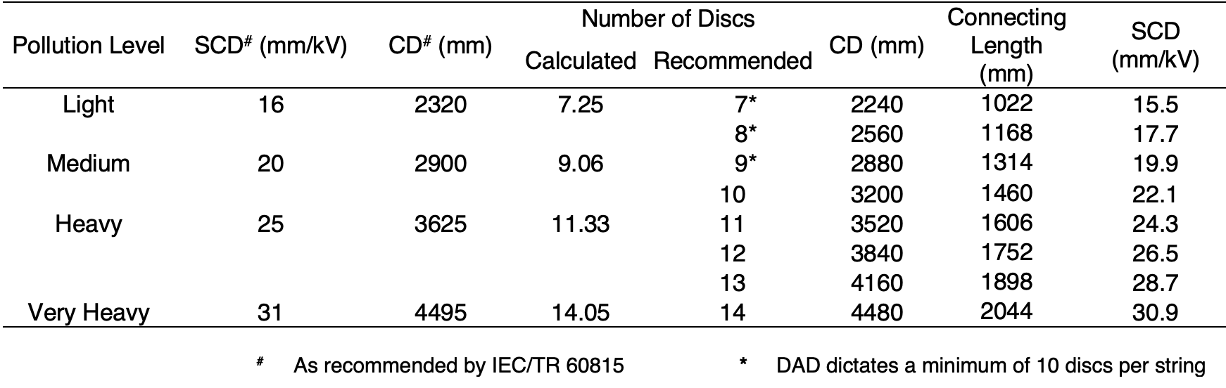
Utilities have typically been using 7 to 14 standard glass discs per string for 132 kV lines. More recently, with the advent of new ‘active’ polymeric insulation materials that interact with the environment, utilities have continued to use IEC/TR 60815 since nothing else was available in IEC.
Typically, for a.c. polymer insulators, utilities such as Eskom would specify maximum connecting length (taking into account live line work), minimum dry arcing distance and minimum creepage distance. They would also state that insulator profile must:
1. comply with IEC/TR 60815 based on in-service and test station experience;
2. have open aerodynamic alternating shed profile with S/P ratio ≥ 1; and
3. that the material must be hydrophobic, with good hydrophobicity transfer capabilities.
Then, for e.g. ease of stock, minimum SCDs of 20 mm/kV for Light to Medium and 31 mm/kV for Heavy to Very Heavy pollution areas would be specified.
Insulation requirements for both UHV a.c. and d.c. insulators are more complex and normally determined along with technical experts from manufacturers (mostly members of Cigré WGs).
Using Latest Specification IEC/TS 60815 “Selection & Dimensioning of HV Insulators for Polluted Conditions”
The following major changes have been made with respect to IEC/TR 60815:
• Encouraging use of site pollution severity measurements, preferably over at least a year, in order to classify a site instead of the previous qualitative assessment (see below).
• Recognition that ‘solid’ pollution on insulators has two components: one soluble and quantified by ESDD; the other insoluble and quantified by NSDD.
• Recognition that, in some cases, measuring layer conductivity should be used for SPS determination.
• Using results of natural and artificial pollution tests to help with dimensioning and to gain more experience in order to promote future studies to establish a correlation between site and laboratory severities.
• Recognition that creepage length is not always the sole determining parameter.
• Recognizing the influence of other geometry parameters and of the varying importance of parameters according to the size, type and material of insulators.
• Recognition of the varying importance of parameters according to type of pollution.
• Adoption of correction factors to attempt to take into account influence of the above pollution and insulator parameters.
Fig. 3 shows three approaches proposed for selection and dimensioning of insulators.
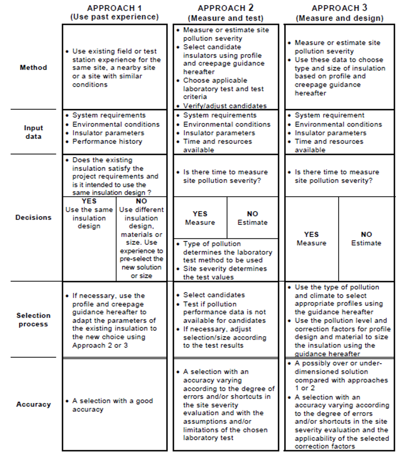
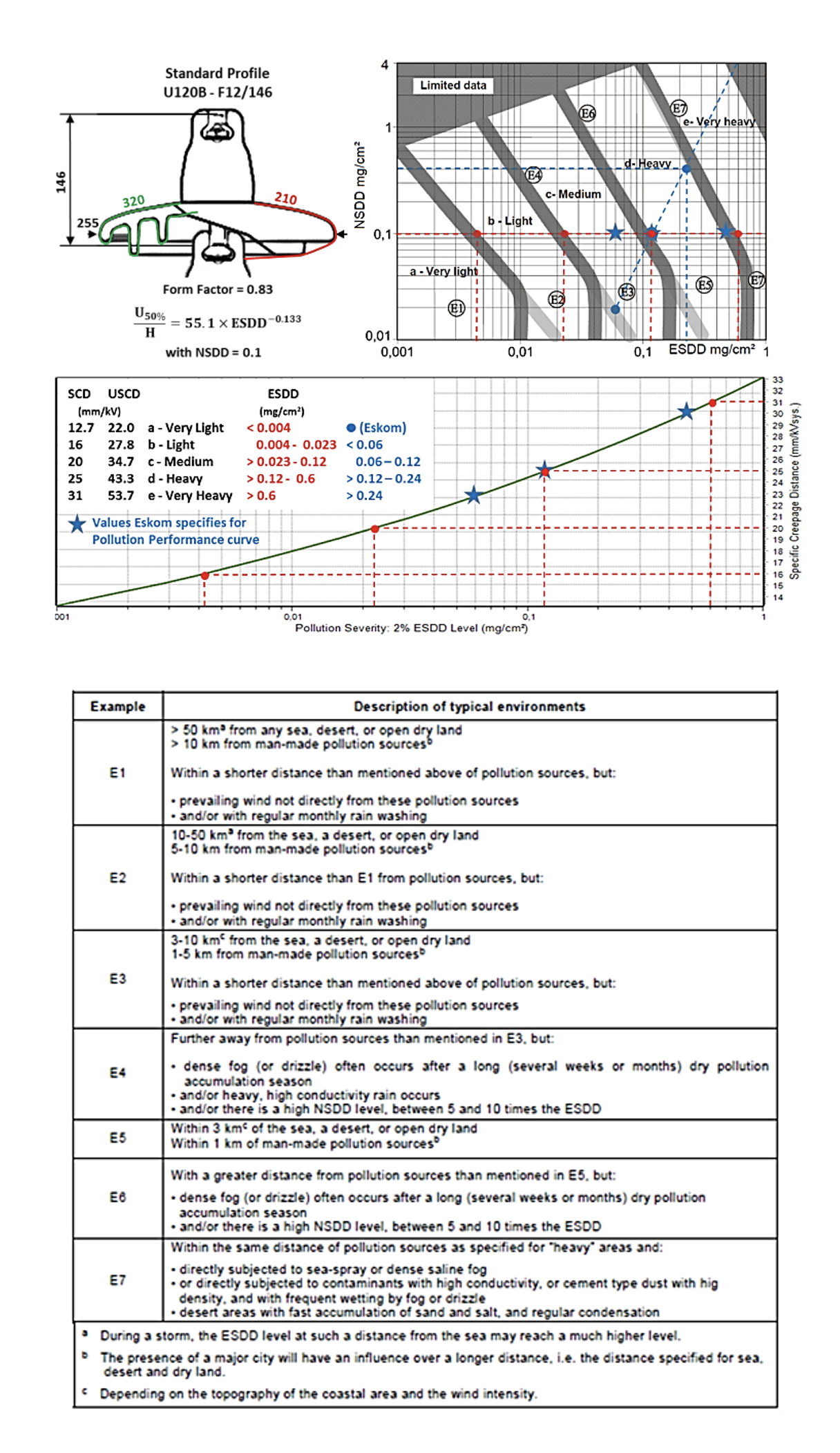
Fig. 4 provides Eskom’s specifications for determining site pollution severity and pollution performance curves.
Practical Example Using Three Approaches as per IEC/TS 60815 for Insulator Selection
It has been proposed to erect a 132 kV substation and interconnecting lines at Koeberg Nuclear Power Station (KNPS) along the South African west coast. The area is approximately 600 m from the coastal high-water mark and is exposed to strong coastal winds, low rainfall and regular salt fog events. The insulators (substation: 189 – posts (4 kN), 294 – hollow cores (average diameter <400 mm), 387 – long rods/strings (120 kN, ball and socket) and lines: 768 – long rods/strings (120 kN, ball and socket)) should have a maximum connecting length of 1.48 ± 0.02 m, minimum insulation length of 1.2 m, minimum dry arcing distance of 1.5 m and minimum specific creepage distance of 31 mm/kV (CD ≥ 4495 mm). In addition, insulators with open aerodynamic alternating shed profiles, S/P ratio ≥1, hydrophobic material and good hydrophobicity transfer capabilities are preferred.
The question is what insulation is required to ensure risk of insulator flashover is minimal, with mean time between flashover (MTBF) of at least 50 years?
Approach 1: Use Past Experience
Duinefontein 132 kV Substation (≈600 m from the coastal high-water mark) is situated only ≈1 km from the new proposed 132 kV substation and interconnecting lines area at KNPS.
In 2004, the 60 porcelain station post insulators installed at the Duinefontein Substation that have a specific creepage distance of 32.4 mm/kV were upgraded (along with all other insulation) using room temperature vulcanized silicone rubber coating (RTV SR A). Prior to this upgrade (since washing did not work and greasing had only a 6 to 12 month effective lifespan) the substation experienced flashovers on an annual basis, including the Type B instantaneous event of February 1999. Since the upgrade, no flashovers occurred to date (18 years later), which includes the catastrophic Type B instantaneous pollution event experienced in February 2006. Indeed, the RTV SR A coating still has excellent hydrophobic properties.
Personnel from the KNPS Weather Station (≈250 m from Duinefontein Substation) classify the area as follows:
• Average ambient temperatures between 14° and 20°C (minimum 4°C and maximum 36°C);
• Exposed to strong coastal winds (gusts up to 35 m/s);
• Low rainfall area (≈320 mm per year) with only 3 to 5 rainy days in summer (≈80 mm)
• High humidity levels at night/early morning and regular salt fog events (≈40 per year).
ESDD, NSDD and DDDG pollution measurements at the Duinefontein Substation from March 2000 to date, were used to calculate ESDD2% = 0.165 mg/cm2 (STDEV = 0.57), average ratio of NSDD/ESDD = 1.1 and monthly average DDDGave = 382 µS/cm.
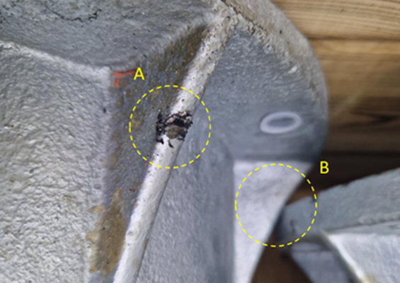
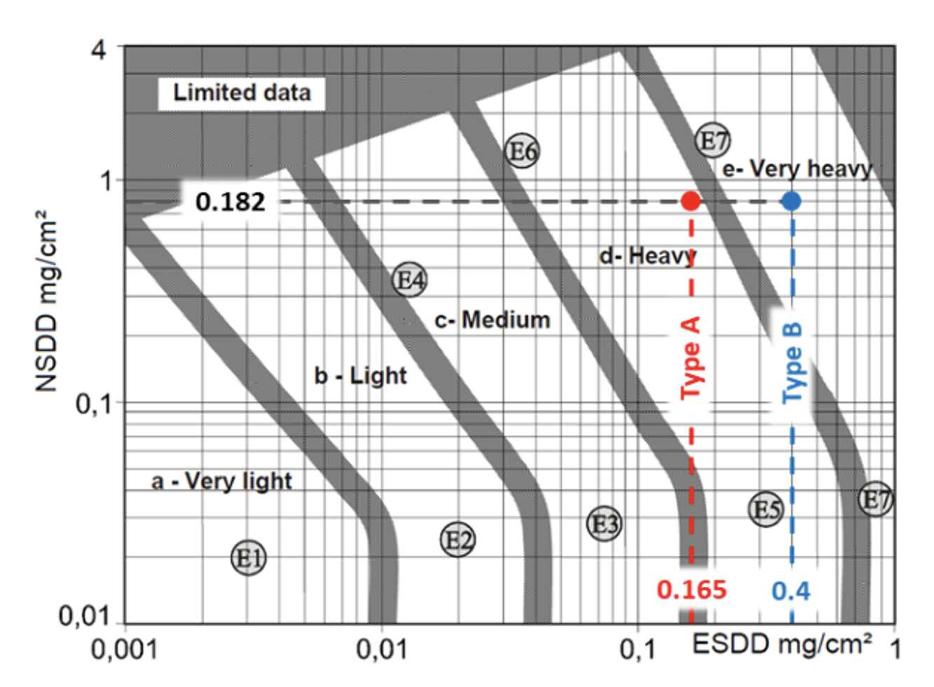
The flashover of a bare porcelain 132 kV breaker support insulator (having specific creepage distance 32.4 mm/kV) during the catastrophic Type B instantaneous pollution event experienced in the Cape in Feb 2006 was used to estimate minimum uniform pollution present on insulation during this event, namely ESDD = 0.4 mg/cm2 and NSDD = 0.182 mg/cm2. Field experience has shown that, while instantaneous pollution events will not occur annually, it can be conservatively assumed that one event occurs each year.
Pollution levels at Duinefontein Substation are as follows:
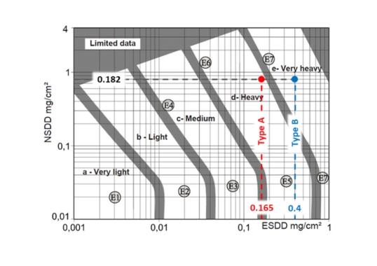
Type A: 40 natural pre-deposited pollution events per year with critical wetting (ESDD2% = 0.165 mg/cm2 with STD deviation of 0.57 and ESDD/NSDD ratio = 1.1).
Type B: One instantaneous conductive fog pollution event per year (ESDD2% = 0.4 mg/cm2 and NSDD = 0.182 mg/cm2).
The SPS levels obtained from ESDD and NSDD measurements at Duinefontein Substation (see Fig 5) classify the area for Type A pollution (E6/7) d – Heavy and Type B (E7) e – Very Heavy. DDDG measurements, after climatic factor correction, classify the area as Very Heavy.
The 60 RTV SR A coated porcelain station post insulators with SCD of 32.4 mm/kV at Duinefontein Substation (≈1 km from the new proposed 132 kV substation and lines area) have provided excellent performance for 18 years. Note: these same 60 bare porcelain station post insulators had flashed over more than once annually. No washing or greasing was recommended.
Koeberg Insulator Pollution Test Station (KIPTS) (≈50 m from the coastal high-water mark) lies about 2 km from the new proposed 132 kV substation and lines area. Monthly average DDDGave = 2522 µS/cm measured at KIPTS is Extreme (≈6.6 times higher compared to Duinefontein Substation). Findings of some insulator research and tests done at KIPTS over 15 years are presented in “Power Utility Perspective on Natural Ageing and Pollution Performance Insulator Test Stations”.
From natural insulator pollution performance experience gained at KIPTS the following:
Posts: Porcelain post insulators with SCD = 38 mm/kV will flashover more than 3 times per year at KIPTS;
RTV SR A coated porcelain post insulators with SCD ≥ 24 mm/kV will have no flashovers per year at KIPTS. RTV SR A coated porcelain transformer bushings at KIPTS with SCD = 30 mm/kV will perform well for 15 years;
Open aerodynamic alternating shed profile with S/P ratio ≥ 1 and a hydrophobic material with good hydrophobicity transfer capability will work best.
Hollows: SR hollow core insulators with SCD ≥ 28 mm/kV will have no flashovers per year at KIPTS;
Open aerodynamic alternating shed profile with S/P ratio ≥ 1 and hydrophobic material with a good hydrophobicity transfer capability will work best.
Longrods: SR longrod insulators with SCD ≥ 22 mm/kV will have no flashovers per year at KIPTS;
Open aerodynamic alternating shed profile with S/P ratio ≥ 1 and hydrophobic material with a good hydrophobicity transfer capability will work best.
Note: Corona rings should be installed on 132 kV longrod insulators.
Strings: Standard glass cap & pin disc insulator (F12/146) strings with SCD of 27 mm/kV will flashover more than 3 times per year at KIPTS. The same insulator string with RTV SR A coating applied will have no flashovers per year;
Fog-type glass cap & pin disc insulator (F120P/146) strings with SCD of 37 mm/kV will have no flashovers per year at KIPTS. The same insulator string with RTV SR C coating applied will experience similar leakage currents to SR longrod insulators.
Note: Expect poor natural washing/cleaning and pin erosion problems.

Approach 2: Measure & Test
Approach 2 (as per Fig. 3) is used along with Section 12 of IEC/TS 60815-2 for porcelain and glass, and Section 12 of IEC/TS 60815-3 for polymeric insulators.
The pollution and climate at Duinefontein Substation (as in Approach 1) give the expected pollution severity levels and climate in the area of the proposed 132 kV substation and interconnecting 132 kV lines as follows:
Type A: (E6/7) d – Heavy as 40 natural pre-deposited pollution events per year with critical wetting (ESDD2% = 0.165 mg/cm2 with STD deviation of 0.57 and ESDD/NSDD ratio = 1.1).
Type B: (E7) e – Very Heavy as one instantaneous conductive fog pollution event per year (ESDD2% = 0.4 mg/cm2 and NSDD = 0.182 mg/cm2).
Candidate insulators were selected as shown in Table 4, where possible with a maximum connecting length of 1.48 ± 0.02 m, minimum insulation length of 1.2 m, minimum dry arcing distance of 1.5 m, minimum specific creepage distance of 31 mm/kV (CD ≥ 4495 mm). Insulators with open aerodynamic alternating shed profile with S/P ratio ≥ 1, and hydrophobic material with good hydrophobicity transfer capabilities. Porcelain post, standard glass and fog type glass insulators were included as reference.
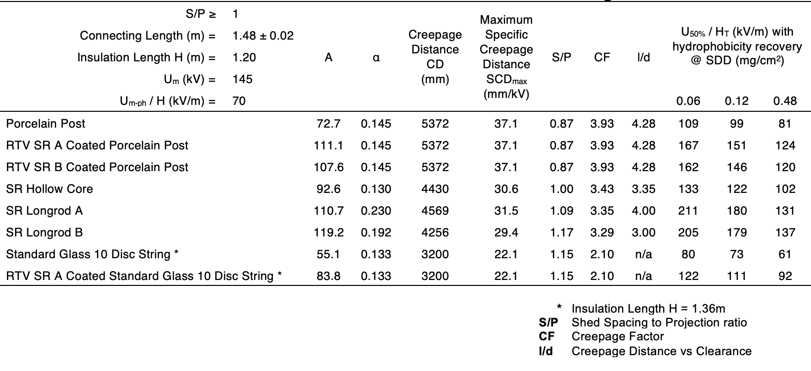
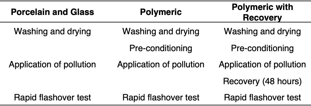
Laboratory pollution U50% flashover voltage (using the rapid flashover test method) curves at three pollution levels (as in Fig. 4) – SDD of 0.06; 0.12 and 0.48 mg/cm2 with NSDD ≥ 0.1 mg/cm2 was obtained using:
• for porcelain and glass insulators the Solid Layer Test Method (see Table 5) according to IEC 60507 using Procedure B and spray gun for applying the Kaolin composition and Annex B.3.2. The degree of pollution on the test insulator was determined using the SDD method. Recommendations as given in Annex D and E were followed.
• and, for polymeric insulators according to modified Solid Layer Test Method (see Table 5) with pre-conditioning procedure, and with/without recovery according to Cigre TB 555 and Cigre TB 691.
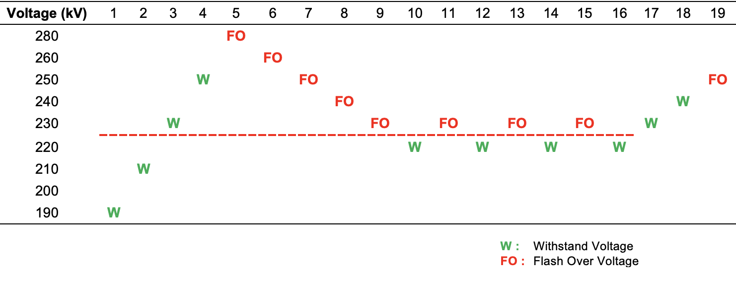
The rapid flashover laboratory solid layer pollution test done on SR Longrod A insulator to determine U50% = 225 kV at SDD = 0.12 mg/cm2 and NSDD = 0.1 mg/cm2 with 48-hour hydrophobicity recovery is shown in Figure 6 as example. The rapid flashover laboratory solid layer pollution test results for all the candidate insulators are shown in Table 4.
The candidate insulators’ pollution U50% flashover voltage results in Table 4 were then converted into flashover stress along the test insulation length HT = 1.2 m as in kV/m and is presented as a three-point approximated inverse power law curves against pollution level SDD in mg/cm2 in Fig. 7.
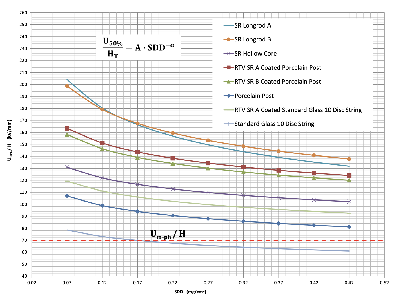
The candidate insulator pollution flashover performance curve constants A in kV/m and α was determined for equation U50%/Ht = A · SDD-α and the values are shown in Table 4.
Um-ph/H was calculated as 70 kV/m using the specified insulation length H = 1.2 m, and Um-ph = 83.7 kV (the highest system r.m.s. phase to ground voltage that the insulator to be supplied will be subjected to).
The candidate insulator was accepted for further calculation if U50%/Ht> 70 kV/m in the SDD range of 0.12 to 0.48 mg/cm2.
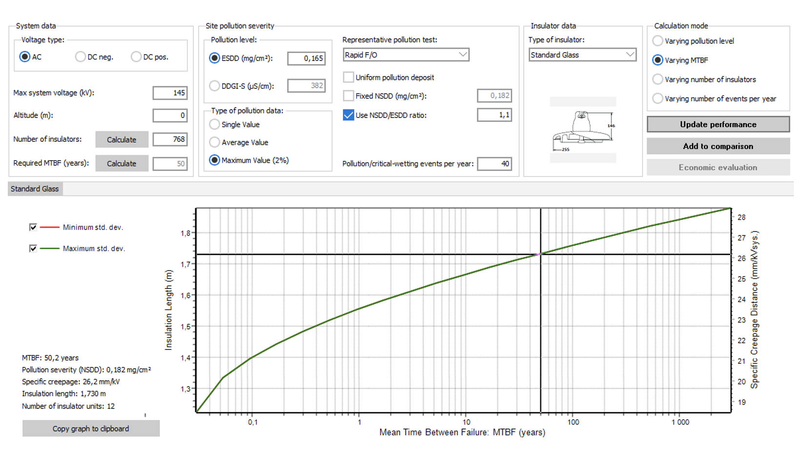
Insulator pollution flashover performance curve constants A in kV/m and α, of the candidate insulators was used along with pollution severity levels and climate in the area of the proposed 132 kV substation and interconnecting 132 kV lines in the statistical approach as per Annex G of IEC/TS 60815-1 in order to optimize insulation selection. Fig. 8 shows the Insulator Selection Tool, a commercially available statistical software.
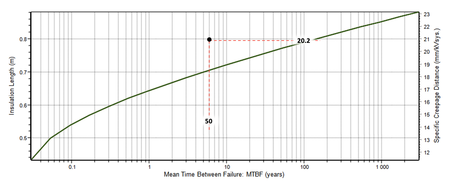
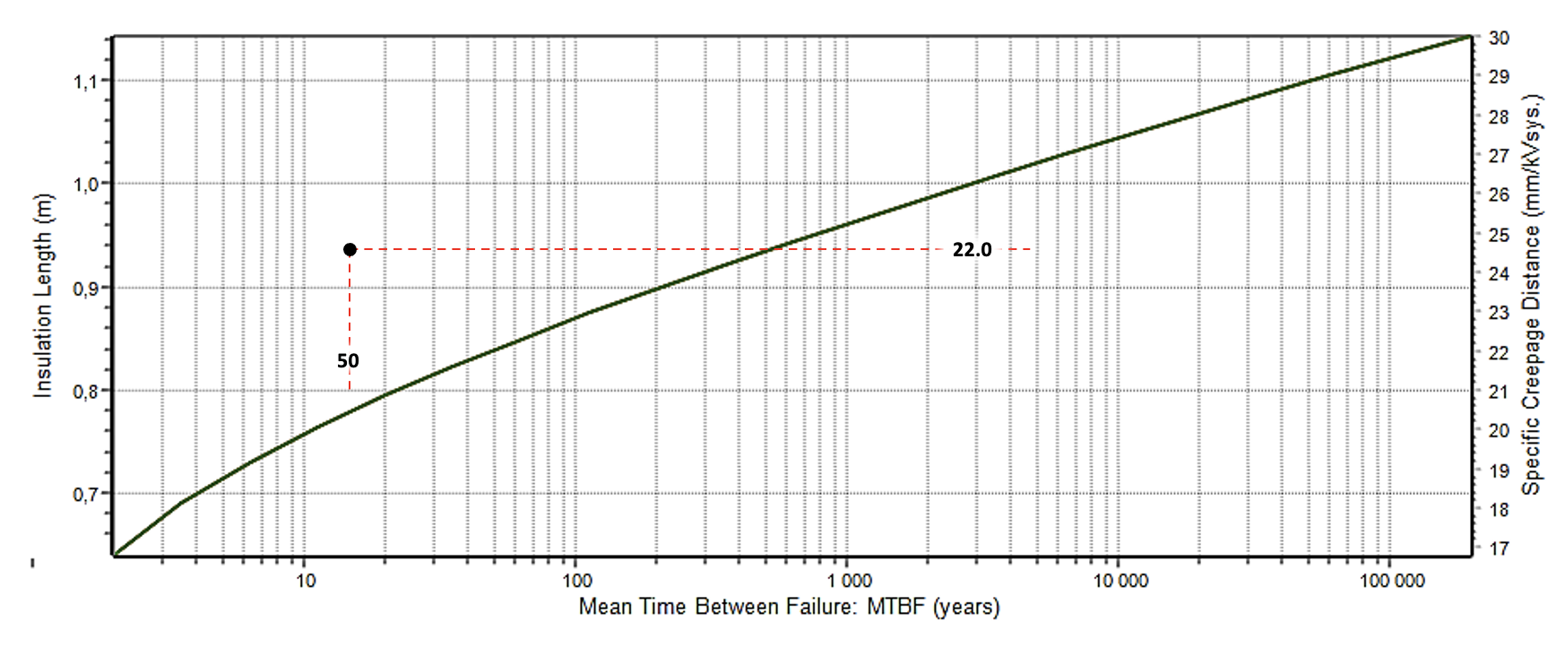
As example, using the IST for MTBF of 50 years 768 – 132 kV SR Longrod A insulators require:
• SCD of 20.2 mm/kV when exposed to 40 natural Type A pre-deposited pollution events per year with critical wetting (ESDD2%= 0.165 mg/cm2 with STD deviation of 0.57 and ESDD/NSDD ratio = 1.1) (see Fig. 9);
• and SCD of 22 mm/kV when exposed to one Type B instantaneous conductive fog pollution event per year (ESDD2%= 0.4 mg/cm2 and NSDD = 0.182 mg/cm2) (see Fig. 10).
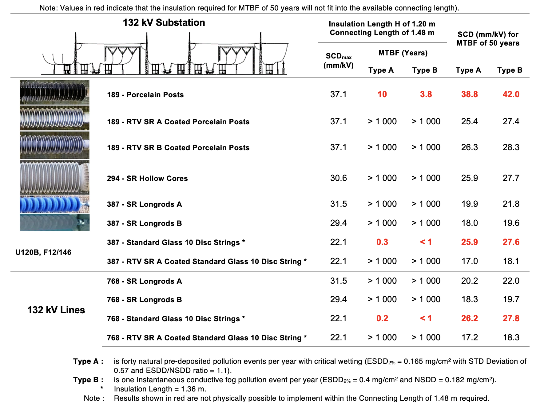
The MTBF obtainable within the required connecting length of 1.48 ± 0.02 m and SCD needed for MTBF of 50 years was calculated for the reference and candidate insulators using the IST. Results are shown in Table 6.

Approach 3: Measure & Design
As per Fig. 5, the area proposed for the 132 kV substation and interconnecting lines can be classified for Type A pollution as Class d – Heavy and for Type B pollution as Class e – Very Heavy. Thus, in the worst case, a minimum SCD of 31 mm/kV is needed for the reference glass disc insulator.
As per IEC/TS 60815-2, the following is recommended for porcelain and glass insulators:
• Aerodynamic, alternating sheds on long rod insulators, post insulators, hollow core insulators;
• Anti-fog profile for disc insulators;
• p1 – p2 ≥ 15 mm, s/p ≥ 0.65, c ≥ 25 mm, l/d ≤ 5, 5˚ ≤ α ≤ 25˚ and CF ≤ 4 (lowest risk options used);
• No altitude correction required;
• 10% increase in SCD for hollow core insulators with average diameter > 300 mm and < 400 mm.
As per IEC/TS 60815-3, the following is recommended for hydrophobicity transfer polymeric insulators:
• SCD could be reduced or increased depending on the environment or pollution level (no clear advice given);
• Aerodynamic alternating sheds;
• p1 – p2 ≥ 18 mm, s/p ≥ 0.75, c ≥ 40 mm, l/d ≤ 4.5, 5˚ ≤ α ≤ 25˚ and CF ≤ 4 (lowest risk options used);
• No altitude correction required;
• 10% increase in SCD for hollow core insulators with average diameter > 300 mm and < 400 mm.
Insulators must have a minimum SCD of 31 mm/kV (CD = 4495 mm) and hollow core insulators with minimum SCD of 31 x 1.1 = 34.1 mm/kV (CD = 4945 mm) are recommended. Table 7 provides a summary and comparison of results obtained for these three Approaches.
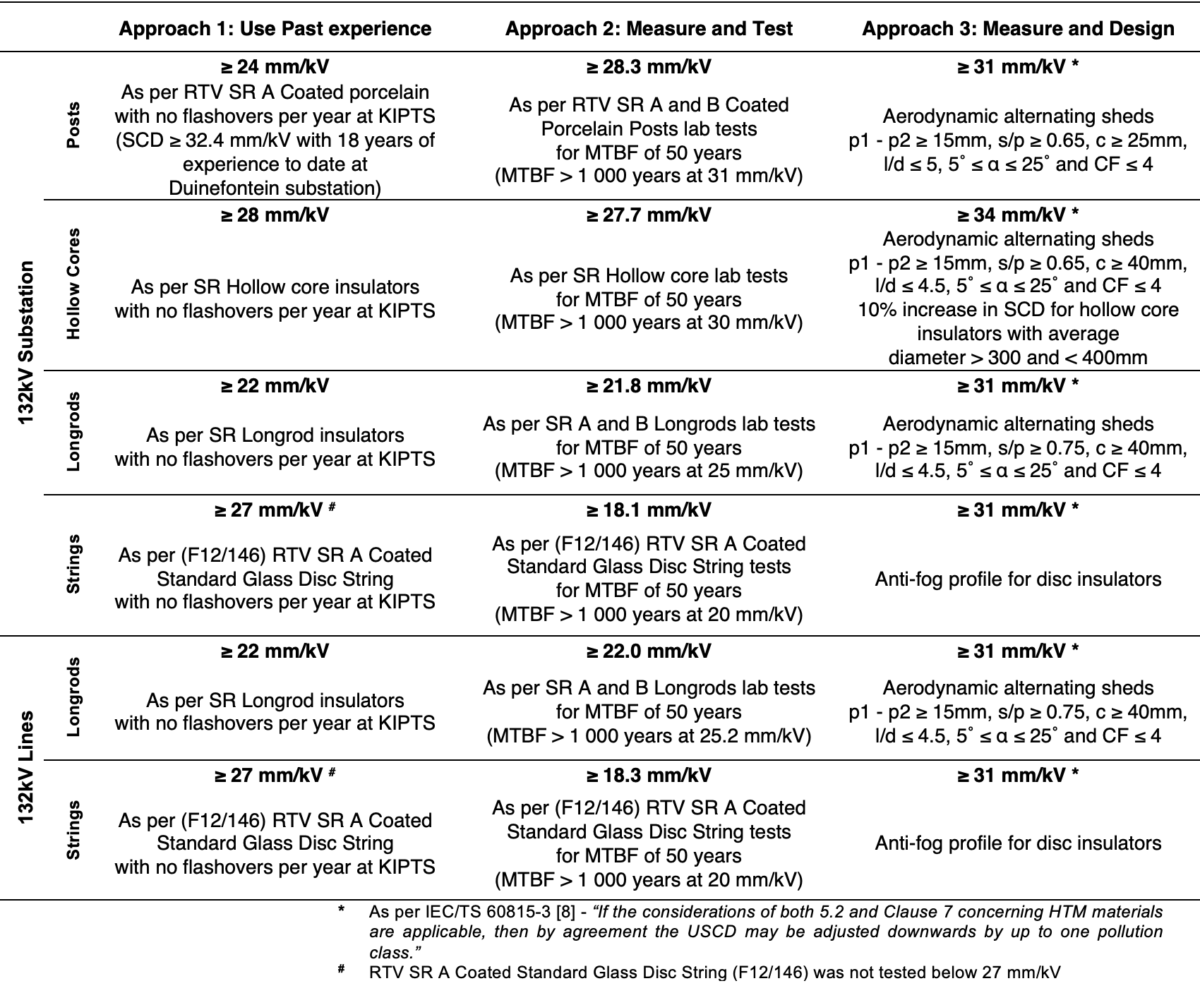
Discussion
As per Table 7, the findings of Approach 1 and 2 correlate with one another, showing that both approaches would work if correct data required as per Fig. 3 is available. The practical examples demonstrate that both approaches lead to a selection having good accuracy. Moreover, as per Table 7, Approach 3 in general would result in over-dimensioning of required insulation.
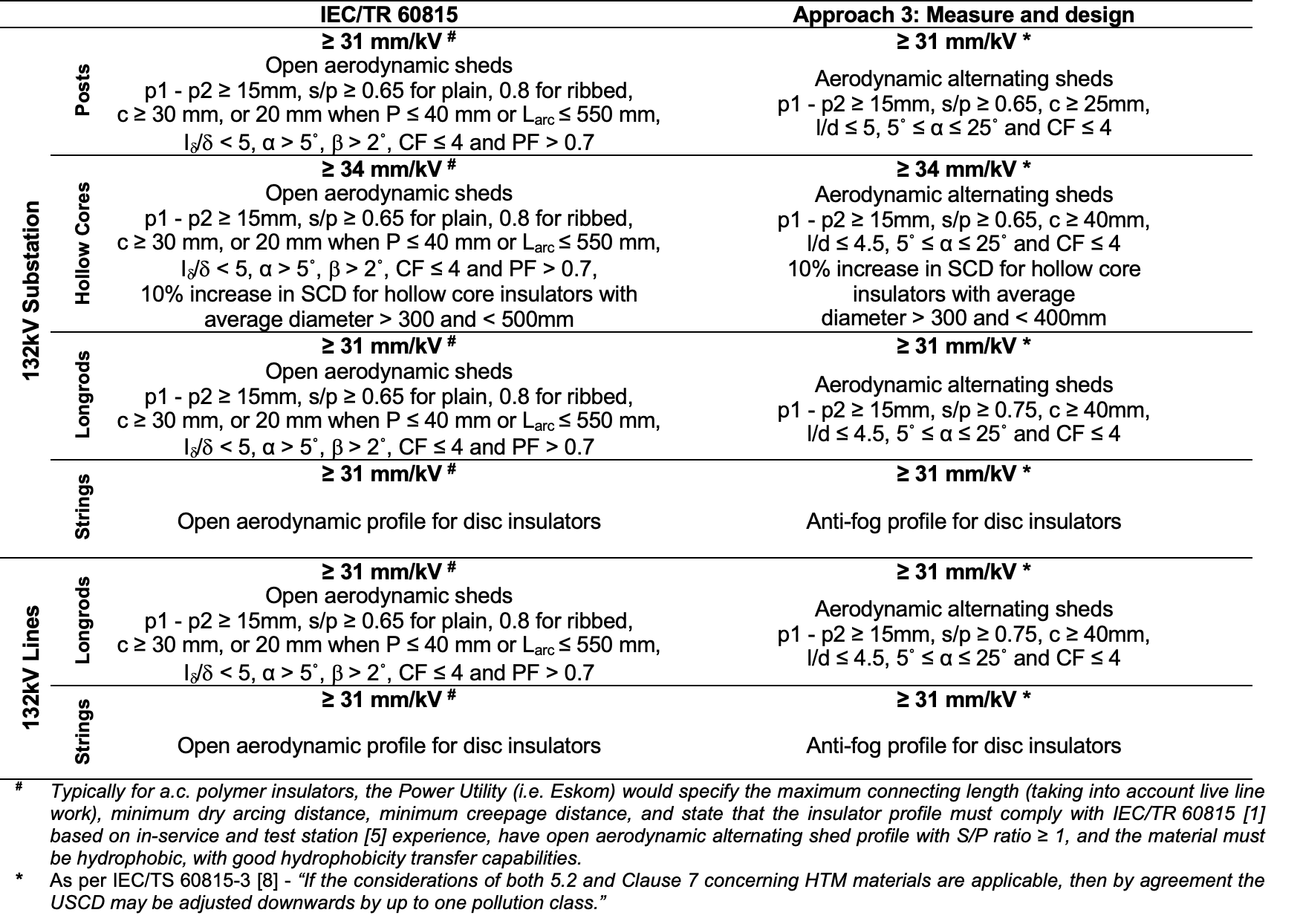
Table 8 offers a comparison of the recommendations as per IEC/TR 60815 and specifications as per Approach 3 in IEC/TS 60815-1 for the practical examples. Findings are similar in regard to specific creepage distance. However, Approach 3 takes into account use of hydrophobicity transfer materials, which could result in a one class lower SCD, different profile parameters and anti-fog instead of open aerodynamic disc insulators.

Conclusions
In summary it has been demonstrated with practical examples, how the old technical recommendation, i.e., IEC/TR 60815 and the new technical specification i.e., IEC/TS 60815 are being successfully applied by a utility, in this case, Eskom, to select and dimension outdoor insulators for polluted environments (Note: Ageing and failure modes are not taken into consideration in this discussion).
The importance is also shown of site pollution severity measurements, climatic conditions, identifying pollution type and practical use of data collected from natural pollution test sites, in-service insulators, laboratory pollution flashover tests and statistical evaluation.
References
[1] IEC/TR 60815, Guide for the selection of insulators in respect of polluted conditions. 1986.
[2] IEC/TS 60815-1, Selection and dimensioning of high-voltage insulators intended for use in polluted conditions – Part 1: Definitions, information and general principles. 2008.
[3] W. L. Vosloo, R. E. Macey, and C de Tourreil, The practical guide to outdoor high voltage insulators. Eskom Power Series, 2004.
[4] IEC 507, Artificial pollution tests on high-voltage insulators to be used on a.c. systems. 1991.
[5] W. Vosloo and R. Davey, “Power utility perspective on natural ageing and pollution performance of outdoor insulators,” IEEE Electrical Insulation Magazine, vol. 36, no. 4, pp. 56–66, 2020.
[6] W. L. Vosloo and F. Potgieter, “Western Cape Power Failures in February 1999.”
[7] IEC/TS 60815-2, Selection and dimensioning of high-voltage insulators intended for use in polluted conditions – Part 2: Ceramic and glass insulators for a.c. systems. 2008.
[8] IEC/TS 60815-3, Selection and dimensioning of high-voltage insulators intended for use in polluted conditions – Part 3: Polymer insulators for a.c. systems. 2008.
[9] IEC 60507, Artificial pollution tests on high-voltage ceramic and glass insulators to be used on a.c. systems. 2013.
[10] Cigrè Working Group C4.303, “Artificial pollution test for polymer insulators – Results of round robin test, Technical Brochure 555,” 2013.
[11] Cigrè Working Group D1.44, “Pollution test of naturally and artificially contaminated insulators, Technical Brochure 691,” 2017.