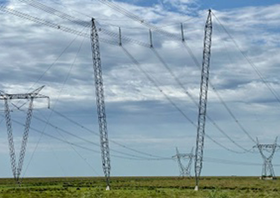
German TSO Amprion has had nearly 60 years’ experience with composite line insulators on its network, dating back to when these were first introduced. Since then, successive generations of these insulators have been refined to overcome initial problems such as erosion and mechanical deterioration such that the technology has achieved improved durability, efficiency and cost-effectiveness.
This edited contribution to INMR by Kübranur Varli and Jeremy Unterfinger reviews Amprion’s decades-long application of composite line insulators. They explain how the present commitment to this technology is based on service performance, innovative design solutions, ease of handling and lower maintenance requirements. At the same time, lessons learned from long experience, coupled with current and future demand, have driven stringent technical specifications that sometimes exceed international standards.


The first non-ceramic insulators in the 1960s were made from epoxy resin but failed quickly in outdoor applications. This was followed by a composite design using porcelain sheds on a fiberglass rod coated with epoxy resin and applied to lines during the 1970s. Shortly thereafter, the first generation of modern composite line insulators was introduced, consisting of a fiberglass core rod with polymer weathersheds.
Various polymeric housings were used including silicone rubber, EPM, EPDM and these were combined with fillers for better electrical properties. Metal end fittings were attached to the rod using different technologies. This generation of insulators promised significant advantages and drew great interest. However, issues arose after only a few years of operation:
• Tracking and erosion of sheath and shed materials, which led to flashover;
• Chalking and crazing of surfaces, resulting in increased contamination collection, arcing and flashover;
• Reduced contamination flashover strength and related increase in number or frequency of contamina¬tion-induced flashovers;
• Deteriorating mechanical strength, which made it problematic to specify mechanical line loading;
• Loosened end fittings;
• Bonding failures and breakdowns along the rod-sheath interface;
• Water penetration followed by electrical failure.
Given this, some manufacturers chose to cease production. Others, however, conducted extensive research leading to a 2nd generation composite insulator. These new insulators resolved initial problems, provided improved corona resistance, tracking-free sheds and more secure end fittings, along with improved quality control that ensured higher reliability.
Over time, use of grading rings evolved as well. Initially recommended only for voltages of 500 kV and above to minimize radio interference and audible noise, rings were initially relatively small and focused on preventing dry corona activity. But once it was discovered that high electric field near the energized end of a composite insulator can degrade both the fiberglass rod and rubber material, grading rings became larger and more widely applied.
In 1996, it was discovered that water-induced corona degraded rubber material and efforts were directed to further reduce E-fields through more advanced ring design. These days, grading rings are recommended for voltage levels of 230 kV and even potentially at 115 kV, depending on insulator and line specifics.

Structure of Composite Insulators
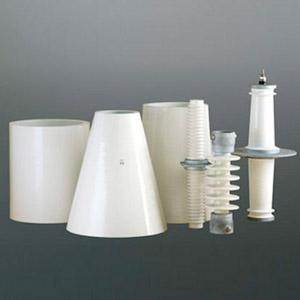
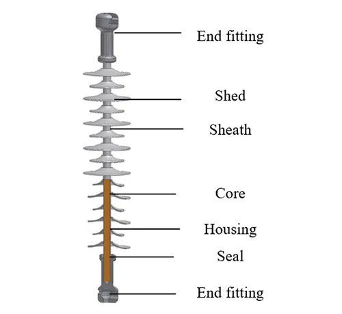
Composite insulators consist of 3 main components: the core, the housing and the end fittings (see Fig. 1). The core is made of glass fiber reinforced epoxy resin and responsible for bearing mechanical loads such as tensile stresses from conductors. Surrounding the core is a housing, ideally made from a hydrophobic material such as silicone rubber. This sheath provides electrical insulation and environmental protection against UV, moisture and pollution. A ribbed housing design increases creepage distance, thereby enhancing performance under polluted conditions. Metal end fittings are crimped or bonded to the ends of the core and serve as mechanical and electrical interfaces to connect the insulator to power lines and support structures.
The core of composite insulators is a composite material made of fibers embedded in a resin matrix. Typically, E or E-CR glass fibers are commonly used, with latter now preferred for its resistance to acids. The polymeric housing shields the core against UV, moisture and discharges such that electrical performance relies largely on housing characteristics and design.
Different types of polymers can be used. Silicone rubber and ethylene propylene diene monomer (EPDM) are favored for transmission insulators, with the former categorized into high temperature vulcanized (HTV), room temperature vulcanized (RTV 1 or 2) and liquid silicone rubber (LSR).
Housing materials must perform under stress and contain additives to achieve desired housing characteristics and optimal processing, often aiming to find the best balance between competing requirements. Additives include silica for strength and alumina trihydrate for reinforcement, with plasticizers and colouring agents for ease of manufacture as well as optimized performance. These are often unique to each supplier formulation. Different manufacturing methods include casting, extrusion, compression or injection molding that produce housings in single or multiple sections.
Advantages
Composite type insulators offer key advantages. For example, lightweight construction and high tensile strength-to-weight ratio enable longer spans and innovative tower designs, reducing infrastructure costs and enhancing efficiency. This also leads to lower transport and installation costs, which become especially important for lines that cross challenging terrains.
Silicone composite insulators offer excellent performance in polluted service areas, maintaining their insulation properties even under severe conditions. This boosts reliability and reduces maintenance. In addition, their design reduces risk from vandalism by withstanding damage from projectiles, thereby minimizing disruptions. Moreover, their flexible design provides superior seismic capability, helping prevent failures during earthquakes and preserving system integrity.
In apparatus bushings, application of hollow core composite insulators protects surrounding equipment from collateral damage in the event of explosive failure. Their housing also offers increased creepage distance, aiding performance in polluted or humid environments and better aligning with standards such as IEC 60815. The hydrophobicity of silicone rubber results in water droplets instead of conductive films, minimizing leakage currents and pollution-induced flashovers. Low permittivity and dielectric loss in the housing material also diminish power losses and thermal stress, while robust resistance to partial discharges enhances reliability.
Composite insulators also resist lightning-induced flashovers, improving system reliability during extreme weather. They exhibit durability against UV, temperature fluctuation and chemical degradation, ensuring longevity in harsh environments. These insulators require minimal maintenance due to their self-cleaning surfaces and inherent contamination resistance. In addition, their design flexibility allows customization to meet specific system needs, optimizing performance through tailored solutions in shed profile, creepage distance and dimensions.
Composite insulators are now favored at Amprion across all various high voltage line applications due to their mechanical strength, electrical reliability and operational efficiency.
Role & Development of Composite Insulators
While insulators constitute only a small proportion of the total cost of constructing new transmission lines, they are nevertheless a crucial component. Failure of an insulator can have severe consequences. Without functioning insulators, there is risk of short circuit, which can lead to power outages. This can compromise stability of an entire network and cause widespread interruptions in power supply. Risk to safety increases as well since damaged or failed insulators can no longer prevent contact between lines and poles, potentially endangering humans and wildlife. Additional expenses such as increased maintenance can significantly affect financial performance while repair costs and the cost of an essential line being out of service can be significant.
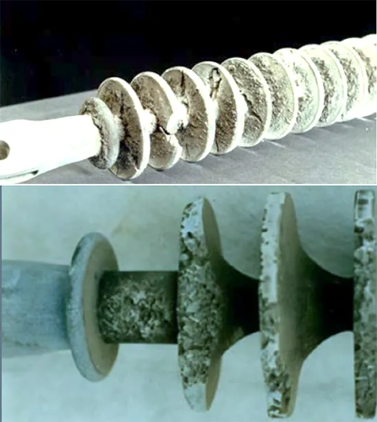
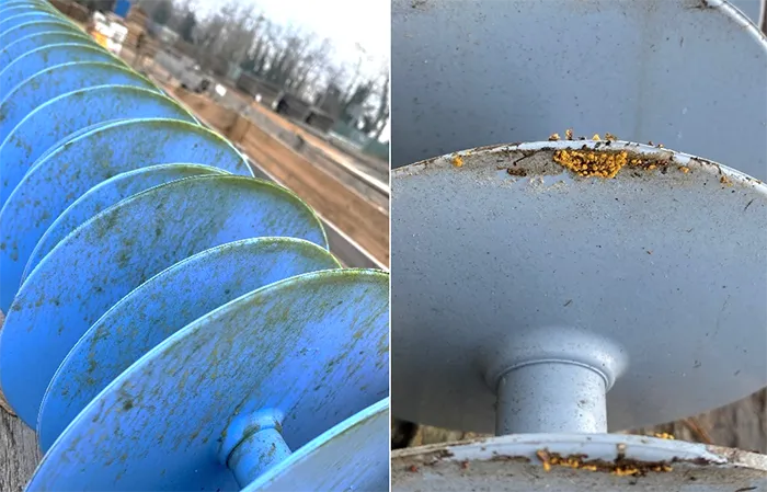
Amprion has operated composite insulators since 1967. As discussed, various generations of composite insulators were developed over the years and continuously improved to address emerging issues and enhance performance. Generation 1 (1967 to 1975), for example, faced challenges from severe erosion as well as salt and dirt deposits (see Fig. 2). The RTV material became brittle and more susceptible to damage, while a porous seal allowed water to penetrate into the core at the end caps, resulting in hydrolysis and formation of nitric acid.
Improvements by Generation 2 (1975 to 1980) included introduction of HTV silicone, which was more elastic and resistant to erosion as well as use of reinforcing resin for sealing to make rods more resistant to hydrolysis.
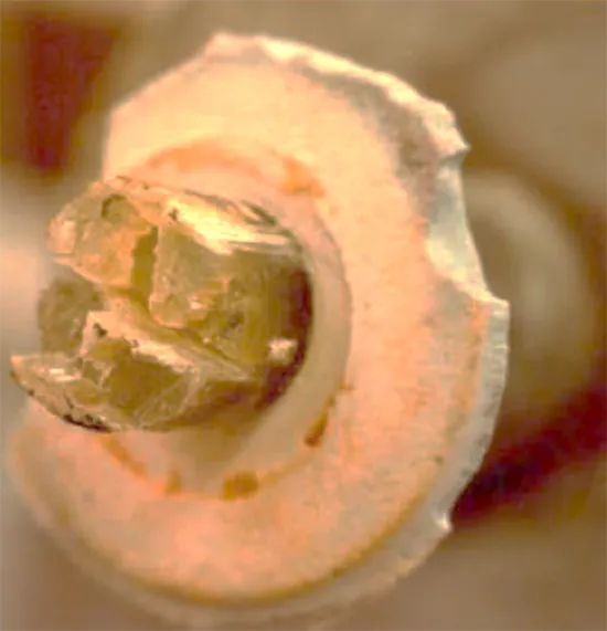
However, Generation 2 still encountered problems such as brittle fracture due to cap construction and formation of nitric acid through electro-chemical reactions (see Fig. 3). Generation 3 aimed to address this by replacing reinforcing resin with metastable silicone gel and switching from E-glass to acid-resistant ECR glass.
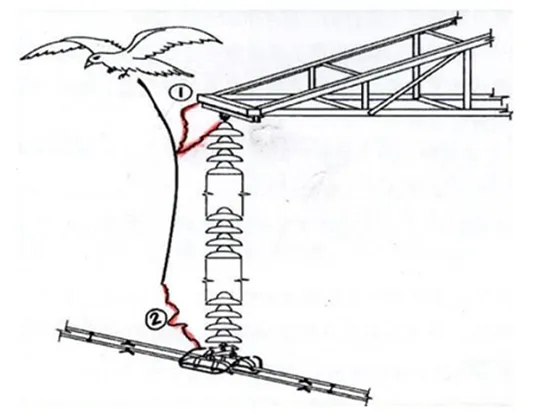
Further anomalies were observed with Generation 3, including flashovers that occurred most during morning hours and which were discovered to be due to bird streamers. Birds leave streaks of droppings when taking off and this can lead to field distortion and risk of flashovers (see Fig. 4). As a countermeasure, it was decided to lengthen insulators from 3.0m to 3.4m. Another change was replacement of wedge type fittings (caps) with press-on (crimped) fittings. Formulation of the silicone material was also improved.
Amprion has used composite insulators exclusively for every new construction and refurbishment project since 2008, gaining even more experience in their application. Up until 2019, composite insulator strings were installed on towers designed for ceramic strings thus maintaining the option to revert back if necessary. Over the years, however, confidence in their performance and reliability has grown substantially. This evolving trust has even led to development of a whole new family of towers and there is no longer any provision to revert to ceramic insulators.
Several important benefits have been achieved through exclusive use of composite insulators. For example, these insulators have enabled construction of smaller structures with reduced right of ways. This has not only minimized environmental impact and cut land acquisition costs but also improved public acceptance. As a result, approval processes have become smoother and faster.
Moreover, the lightweight design of composite insulators simplifies transport and installation, saving time and reducing labor costs. Coupled with their superior tensile strength to weight ratio, this has allowed Amprion to operate at higher conductor tensions using composite insulators in double string configurations. Porcelain insulators, by contrast, already reach their limits, even in triple strings.
Similarly, the flexible design of composite insulators is advantageous for load re-distribution in the string, which contributes to the reliability of composite insulator strings. Overall, their durability also enhances reliability and reduces maintenance needs, leading to smoother operations and greater efficiency. Ultimately, these benefits contribute to lower total project costs, making composite insulators valuable assets during infrastructure development.
Amprion’s nearly 60 years of experience, coupled with current and anticipated demands, have driven stringent technical specification for composite insulators, featuring requirements that sometimes exceed those outlined in IEC standards. The aim has been to always choose the optimal insulator design for any application.
For every new supplier, Amprion has a pre-qualification process to ensure that the manufacturer can produce and control high quality products, while also considering the needs of its workers. Also, there are clear guidelines for factory visits to evaluate quality control during the production process. Moreover, Amprion witnesses Factory Acceptance Tests for each batch of insulators produced to verify that they have been manufactured according to its drawings and specifications.
In addition, Guides for composite insulators have been established that define optimal areas for their application compared to ceramic insulators. As for storage and construction, Handling Guides for composite insulators have been established to make sure no damage can occur to them during typical handling practices.

Qualification Process
Amprion’s process to qualify new suppliers of composite insulators for its transmission lines involves the following:
• assurance of meeting specifications;
• creation of corresponding drawings;
• development of prototypes;
• preliminary examinations;
• design and type testing;
• trial shipments; and
• final audits to ensure compliance with standards.
During these audits, several key technical areas are examined, including crucial steps during manufacture:
• pressing (crimping) of the end fitting onto the rod;
• application of primer to ensure seamless adhesion between silicone and rod;
• adhesion between housing and sheds in the case of the modular production method;
• transitions between individual sections for the injection molding process; and
• tight seals devoid of gaps or bubbles and with adequate capabilities for verification.
Testing processes involve routine, incoming goods, acceptance, type and design tests, along with quality control of incoming raw materials. Documentation is essential during these processes and should cover all tests, discrepancies, actions taken during tests, while also ensuring full traceability. Important additional considerations include storage of raw materials and presence of any harmful or reactive materials.
Maintenance and upkeep in the plant are also regarded as vital, as are research and development activities that encompass laboratories, equipment and who at the supplier participates in R&D committees. Every step in the sequence must be passed successfully. Once a contract is awarded, any product changes by the manufacturer are permitted only with prior approval.
Required approvals also extend to sub-suppliers such that a list of these as well as their locations must be provided. To ensure compliance with specifications, Amprion also requests audit documents from these sub-suppliers while retaining the right to conduct its own audits at their facilities. Any changes or additions to sub-suppliers must also be approved.

Material Requirements
The core for composite insulators must be designed as a fiberglass-reinforced epoxy resin (GRP) rod with high strength as well as resistance to changes in temperature. The fiberglass is to be resistant to acid attack to prevent stress corrosion at the core rod. The amount of glass in the core is identified through density measurement according to CIGRE TB 595 or with the help of a microwave incinerator. The core must also be resistant to hydrolysis.
The housing is to be made from HTV silicone elastomer, ensuring uniform thickness along the rod as well as surface hydrophobicity. Minimum requirements for the silicone material are defined in IEC 62039. One key filler is aluminum trihydrate (also known as aluminum trihydroxide or ATH), which is to be used exclusively in its silanized form. Volume percentage for ATH is to be chosen to guarantee the optimum balance between hydrophobicity transfer and erosion resistance. To identify any changes in material composition, Amprion selects random samples once a year and performs fingerprinting tests according to CIGRE TB 595.
A primer as an adhesive surface is to be used between core rod and housing but is not permitted in the press (crimp) area of the end fitting. Only non-conductive primers are permitted and, to ensure their proper application, these must be colored to allow visual differentiation from the core.
End fittings are to be produced from hardened and tempered steel (min. C45E in accordance with DIN EN 10083-2). Tensile strength must be such as to meet the insulator’s minimum required breaking load. To ensure constant deformation during the process of crimping the fitting onto the rod, yield strength of the material must fall within a narrow tolerance window.
All metal parts, except for stainless steel and copper, are to be galvanized in accordance with DIN EN 60383-1. The zinc coating can be a minimum of 85µm but no more than a maximum of 180µm. Galvanization is to be performed in accordance with DIN EN ISO 1461 and DIN EN ISO 4042. Composite insulators are to be equipped with crimped clevis fittings and the corresponding connecting bolts must have galvanized copper split pins (DIN EN ISO 1234), which must be able to be bent by hand.
The gap between end fitting and housing is to be sealed using metastable silicone elastomer with permanent elasticity and by a vertical sealing process. The seal must be located between the surface of the end fitting and the housing and is to be formed mainly by the metastable silicone. Sealing by compression (crimping on the housing) is not permitted since this method does not ensure permanent sealing and involves risk of cavity formation in the event of volume changes in the end fitting, such as from temperature fluctuations. It must be possible to always assess the metastable silicone elastomer. Therefore, spraying or overcoating the end fitting with the housing material is also not permitted.
Insulators must be dimensioned to ensure optimal positioning of grading rings based on the limit values proposed in Reference #4 (at the end of this contribution). Tangential electric field stress along any 10mm of housing surface should on average be less than 0.42 kV/mm. Tangential electric field stress at the triple point should not exceed 0.35 kV/mm. Normal electric field stress on the surface of end fittings and grading rings should be a maximum of 1.8 kV/mm. Optimal positioning and suitability of grading ring design is to be verified by means of 3D field simulations.
Specific Requirements Beyond IEC
1. Sealing at Triple Point
That part of the insulator closest to the triple point must be properly manufactured since poor-quality sealing over the long-term can result in damage and failure. For example, low quality sealing can allow air bubbles into the seal or lead to poor adhesion between the seal and other insulator components. Such issues could then allow moisture penetration followed by corrosion which could be accelerated by discharge activity.
Amprion requires that sealing of insulators be performed in a vertical orientation to prevent formation of air bubbles. Once sealed, the insulator must cool at room temperature for 4 hours before being turned and sealed at the opposite side. It is regarded as crucial to allow the sealing to cool in this position, since gravity aids in preventing air bubbles and ensures any voids are filled with sealant. The insulator should always be entirely cool before proceeding with the vertical turn.
Since there is still no reliable standard test to evaluate quality of sealing at the triple point, a research project was performed on behalf of Amprion by expert consultants. Findings from the project were used to implement an additional type test into product specification requiring that the quality of the sealing method be studied using two samples. The test involves intentionally initiating galvanic corrosion to assess its impact on seal impermeability at the interface between end fitting and housing.
The end fitting is placed into a metallic container with 10l of salt water, i.e. a mix of tap water and NaCl at 100 g/l concentration. DC voltage of about 10V is applied for 2h, focusing the current on the interface by insulating most of the end fitting with plastic foil and tape. The exposed metal surface is wiped every 20 minutes to maintain current flow. Afterwards, the end fitting is cleaned and boiled in fresh salt water for 24h. Upon cooling, visual inspection is performed looking for signs of trapped water, corrosion or deterioration. The test is passed if none of these are found.
2. Adhesion Between Core & Silicone Housing
Adhesion and bonding of the silicone housing to the core rod is particularly important to prevent ingress and condensation of water vapor in the boundary layer. This could become conductive, leading to premature failure. Investigations from past service failures have identified that the underlying cause in many cases was insufficient adhesion at the junction between fiberglass core rod and silicone rubber housing.
Despite evidence of this issue, poor adhesion has not been detectable using IEC steep-front tests designed to assess integrity of composite insulator interfaces. In response, a consortium of 9 European power companies, including TSOs and DSOs, initiated collaborative research aimed at developing a robust and effective method to evaluate quality of adhesion at the core-housing interface.
The primary objective of the project was to establish practical testing methodologies to identify poor adhesion in composite insulators by sampling batches procured and made available for inspection by the end user prior to shipment and installation. Based on this project, an adhesion test as a design test was added to Amprion specifications. This includes a 100h water diffusion test followed by a pull off test performed according to the methodology outlined in References #9 and #10.

Fingerprinting Silicone Insulators
To ensure consistently high quality of the silicone material and core rods used in production, the composite insulator manufacturer is required to record the fingerprint of the silicone and core with Amprion. This fingerprint is a clearly defined characteristic of the materials used in various processes and must be produced in accordance with CIGRE TB 595.
Glass content of the core, for example, is determined using density measurement in accordance with ISO 2781. Glass transition temperature is an indicator of degree of cross-linking of the epoxy resin rod and is to be determined using differential scanning calorimetry in accordance with DIN EN ISO 11357-3. Moreover, silicone also has a glass transition temperature and if this is reached the material can become brittle and break. Glass transition temperature therefore helps characterize a silicone material.
Fingerprinting, as described above, makes it possible to compare the characteristics of the silicone and core of any composite insulator against the applicable specification. The aim is to detect possible changes in silicone composition compared to the valid required composition and to ensure sufficient cross-linking of the epoxy resin rod. A fingerprint also assures the mechanical characteristics of the core, which are related to amount of glass.
Porosity Test of Core
During factory acceptance testing, a porosity test of the core is fulfilled as well. Although this test is a design test in IEC 62217, Amprion requires it for each batch to be certain all cores are tight. The test is performed as per IEC 62217 and passed if no dye can be seen on the surface of samples after 15 minutes
Handling, Storage & Installation
As part of a Benchmarking Project for composite insulators conducted in cooperation with other TSOs, a Handling Guide was created covering transport, storage, installation and maintenance of composite long rod insulators. This was added to Amprion specifications for transmission line components. The Guide provides information on requirements during installation, required tools as well as procedures to verify correct positioning of protective fittings. Some repair measures, along with maintenance instructions, are also included (e.g. how best to remove paint stains). Everything is also visually depicted (see Fig. 5).

Maintenance Processes
Various measures are carried out regularly for maintenance and inspection of transmission lines, including annual inspection of the route, towers and fittings to identify any needed condition-based repairs. Semi-annual or event-driven inspections, particularly for load-bearing temporary solutions, are conducted based on a 6-month follow-up. Aerial surveys are also conducted each year, with no follow-up provision for missed flights.
Intensive inspection of conventional lattice towers and fittings takes place during the first 3 years post-construction and subsequently every 5 years, with a one-year follow-up. IR thermography inspection of fittings begins post-commissioning and are conducted annually to cover at least 30% of the network. Laser scanning of the route is also conducted to update profile plans and identify vegetation threatening lines. This takes place one to two years post-construction and then every 5 years thereafter.
Maintenance activities also include preserving tower markings and ensuring functional corrosion protection, both of which depend on condition. Route maintenance focuses on preventing hazardous vegetation growth and updating ecological route management plans and this is completed annually for at least 5% of line routes. Additionally, fittings with independent modules are maintained depending on the condition to ensure power supply. These comprehensive inspection and maintenance measures are crucial to maintain the safety and functionality of transmission line infrastructure.
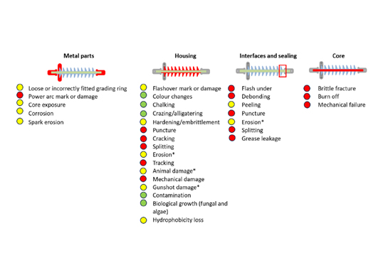
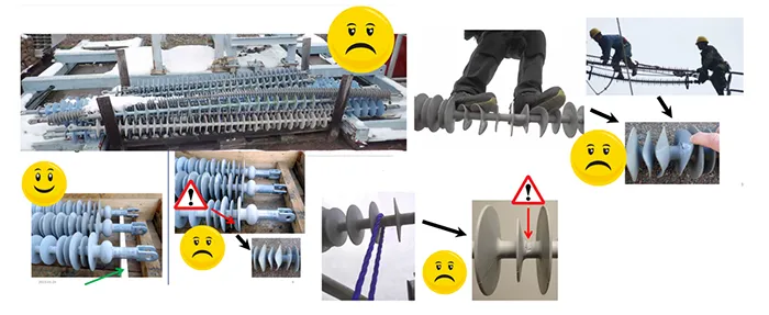
In the frame of a collaborative project with 11 European TSOs and DSOs, a Maintenance Guide focusing on condition of composite insulators was developed and has been added to Amprion’s maintenance strategy. Visible insulator defects are identified during routine or emergency line inspections. Fig. 6 summarizes possible deterioration or damage for each component.
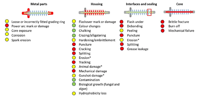
Using a traffic light pattern, the corresponding rating for appropriate action is presented. It is important in this regard to clearly differentiate between a failed and a damaged insulator, even though both are marked red. According to CIGRE TB 481 the criterion failure means that an insulator can no longer support the operational mechanical load or electrical stress. This can be attributed to mechanical failure or brittle fracture (listed under ‘core’) and in both cases the insulator is probably broken, and a conductor is on the ground. In all other RED cases, insulators should be replaced at the first planned outage. This assumption is based on service experience that shows that even a weakened unit with cracks, core exposure, erosion or peeling of seal will survive another year or so due to the relatively slow speed of degradation.
It should be noted that several classifications are marked YELLOW with an asterisk (*) following deterioration level. This indicates that deterioration may be classified as RED, depending on severity. For example, erosion is classified as YELLOW if the core remains unexposed. However, if the erosion is severe enough to penetrate the housing and expose the core, it should be classified RED. Similar considerations apply to other types of deterioration marked with an asterisk.
Amprion’s rigorous standards, combined with detailed qualification, control and maintenance processes, have together ensured reliability of composite line insulators on its system, with no known failures to date. This robust oversight has instilled confidence in their reliability. While there have been cases of deterioration over time, these have provided valuable additional insight and enabled continuous improvement in testing and manufacturing practices.
Such observations underscore an important finding: when composite insulators are well-crafted and appropriately dimensioned for their environmental conditions, they perform exceedingly well, even in the face of minor deterioration. This durability highlights long-term resilience and reliability. Below is a discussion of some of the deterioration patterns observed.
Deterioration & Test Results
1. Bird Pecking on Sheds & Seals
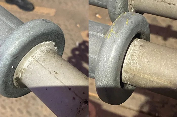
Bird pecking damage to composite insulators has been reported globally, especially for insulators that are not yet energized, shortly after installation or during extended outages. While pinpointing the time of initial damage is a challenge, variations in color of the rubber surface suggest it occurred long after installation. In this case at Amprion, pecking was found primarily on sheds and sealings, with some occurrence on insulator trunks as well. Damage to sheds has been minimal since insulators retain substantial creepage and are operating in a relatively clean environment.
Though seals also suffered from pecking with some parts missing, dye penetration tests conducted on 4 damaged insulators showed no penetration into the sealing materials. This suggests the seals still effectively prevent water ingress that could harm the core/fitting interface and threaten mechanical integrity. Currently, there is no immediate threat to mechanical withstand capability. However, long-term risk exists if the glass fiber core becomes exposed due to severe trunk pecking, which would then require insulator replacement.
It should be noted that missing outer sealings can create cavities that trap water, thereby promoting discharge activity and potential further deterioration over time. But so long as electric field stress and leakage currents remain low, this process will be slow. Fitting design, along with grading rings and arcing horns, helps maintain low field stress and, in low-pollution environments, leakage currents are minimal.
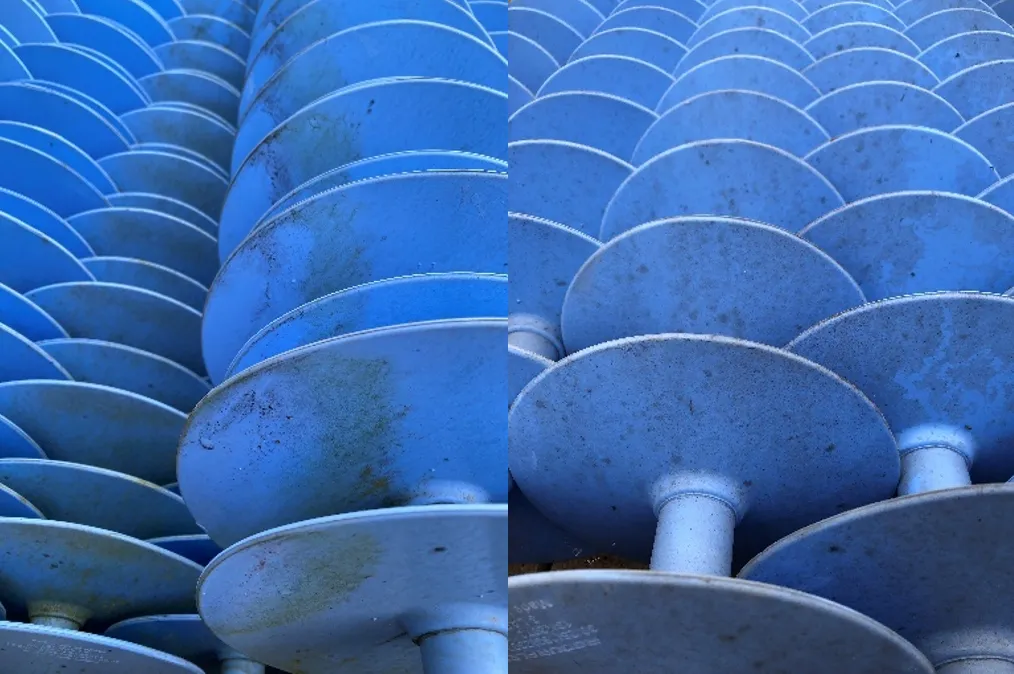
2. Biological Growths
Composite insulators with biological growths have been found in Amprion’s storage and on the network as well (see Fig. 9). To evaluate criticality, research was conducted also involving TSOs in Finland and Sweden that saw laboratory tests performed on biologically contaminated insulators. Results showed that risk of decreased pollution performance is negligible for composite insulators operating in lightly to moderately polluted European environments and where standard creepage is as per IEC 60815.
Biological growths were identified as a surface phenomenon that does not penetrate the material structure of insulators, meaning that regular cleaning is not necessary. If cleaning is carried out for aesthetic reasons, this should be gentle to avoid affecting hydrophobicity. Removal of biological growths is easy by manual cleaning using a mild detergent. Laboratory testing also revealed that biocides to prevent biological growth are still under development and not yet commercially successful.
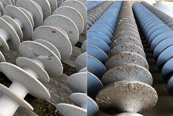
3. Pollution From Improper Storage
During inspections at construction sites, some insulators were discovered to have been exposed to pollutants due to improper storage (see Fig. 10). Despite this oversight, these retained their hydrophobic properties and maintained electrical integrity, thereby only reinforcing their good performance in polluted environments.
4. Paint Splashing
During painting of towers, components underneath can at times be splattered. Especially for composite insulators, the question arises whether paint will affect the material and reduce effective creepage distance.
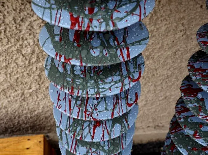
In a series of full-scale laboratory tests, different composite insulators were subjected to paint splashes and evaluated for adherence to standard dielectric properties. The tests measured several values: dry withstand AC voltage, dry flashover AC voltage, rain withstand AC voltage, and rain flashover AC voltage.
Remarkably, despite being contaminated by paint in the laboratory, the dielectric properties of these insulators did not decline compared to reference insulators. This was attributed to silicone’s hydrophobic characteristics, which remain unaffected by such pollutants. Fig. 12, for example, illustrates an artificially contaminated ‘worst-case’ scenario. Tests confirmed that all such artificially polluted samples complied with rain withstand AC voltage standards. No reduction in flashover voltage was detected for any pollution variant compared with a reference insulator.
Summary & Conclusions
An overview of the development of composite transmission line insulators at German TSO, Amprion, has shown notable advancements as well as challenges linked to the evolution of these insulators over nearly 6 decades. Initial generations faced significant issues such as erosion, premature degradation and mechanical failure. Specifically, problems such as tracking, loosened end fittings and bonding failures necessitated design iterations.
Over time, improvements in materials and design such as the changeover to HTV silicone housings and use of acid-resistant glass fibers addressed these concerns while enhancing performance and reliability. Developments in grading rings has evolved as well to reduce electrical stress on these insulators to further extend operational life.
Amprion’s extensive use and rigorous testing of composite insulators have fostered today’s level of confidence, leading to infrastructure innovations such as smaller towers and expedited project approvals due to reduced environmental impact. These insulators also offer logistical advantages due to their light weight, which lowers transport and installation costs. Since 2008, Amprion has used composite insulators exclusively for every new construction and refurbishment project, reflecting full trust in their reliability and performance.
At the same time, implementation of stringent technical specifications and comprehensive pre-qualification processes ensures suppliers adhere to high standards. These go beyond IEC benchmarks with enhanced requirements, particularly with regards to adhesion and sealing, to prevent issues linked to moisture ingress and mechanical degradation.
Collaboration with other major European TSOs has also yielded significant insight into proper maintenance practices, further securing durable service. Despite challenges such as bird damage and pollution from improper storage, these insulators have demonstrated resilience, maintaining their hydrophobic properties and electrical integrity even under adverse conditions.
Rigorous standards, control and maintenance strategies have ensured reliability of composite insulators, with no known failures to date. Observing possible patterns of deterioration has provided valuable insights that enable further improvements in testing and manufacturing practices. Ultimately, despite challenges, the resilience and reliability of composite insulators remain evident and support Amprion’s infrastructure with minimal maintenance and required operational integrity.
References
[1] W.L.Vosloo, R.E. Macey, C. de Tourreil: “The Practical Guide to Outdoor High Voltage Insulators”.
[2] Insulator Reference Book. EPRI, Palo Alto, CA: 2017. 3002010140.
[3] K. O. Papailiou and F. Schmuck, Silikon Verbundisolatoren, 1st ed. Springer Verlag Berlin Heidelberg, 2012.
[4] P. Sidenvall, I. Gutman, A. Deckwerth, L. Diaz, P. Meyer, J.F. Goffinet, K. Halsan, M. Leonhardsberger, M. Radosavljevic, P. Trenz, K. Varli, K. Välimaa: “Limits of electrical field for composite insulators: state-of-the art and recent investigations of insulators purchased by power utilities”, Cigré Science & Engineering, N. 24, February 2022, p.p. 1-14.
[5] K. Varli, S. Steevens, J. Unterfinger, A. Dernfalk, I. Gutman, J. Lundengård, P. Sidenvall: “Benchmarking of sealing systems of composite insulators: ideas for innovative test methods”, CIGRE Science & Engineering, N. 25, June 2022, p.p. 108-131.
[6] M. Radosavljevic, T. Lindquist, I. Gutman, A. Dernfalk, “Design considerations for modern 400 kV AC substation in coastal area: what is missing in IEC/CIGRE requirements”, CIGRE-IEC Colloquium on EHV and UHV, Montreal, QC, Canada, May 9-11, 2016, paper 54.
[7] I. Gutman, J. Lundengard, C. Ahlrot, “Need of standardized adhesion test for composite insulators: lessons learned from service experience”, 20th ISH-2017, Buenos Aires, Argentina, August 28 – September 01, 2017, paper 145.
[8] I. Gutman, P. Sidenvall, T. Condon, P. Flynn, P. Shiel, “Evaluation of composite insulators with internal deterioration: lessons learned from service and after-service testing”, CIGRE Winnipeg 2017 International Colloquium & Exhibition.
[9] Gutman, C. Ahlrot, P. Aparicio, A. Berlin, T. Condon, A. Dernfalk, J.-F. Goffinet, K. Halsan, K. Kleinekorte, J. Lundengård, M. Radosavljevic, P. Sidenvall, S. Steevens, K. Varli, K. Välimaa: “Development of Innovative Test Procedure for Evaluation of Adhesion of Core-Housing of Composite Insulators: from Root Cause of Failures in Service to Reproducible Test Procedure”, Cigré Science & Engineering, N. 20, February 2021, p.p. 171-182.
[10] Gutman, A. Dernfalk, J. Lundengård, P. Sidenvall, A. Deckwerth, L. Diaz, K. Halsan, M. Leonhardsberger, M. Radosavljevic, P. Trenz, K. Varli, K. Välimaa: “Test methods and criteria for validation of functional properties of composite insulators related to materials and interfaces”, CIGRE-2022, D1-10828.
[11] M. Jalonen, K. Välimaa, I. Gutman, A. Deckwerth, K. Halsan, M. Leonhardsberger, L. Diaz, P. Trenz, K. Varli: “Benchmarking Composite Insulators: Utility Perspective & European Initiative”, 2023 INMR World Congress, Bangkok, Thailand, 12-15 November 2023.
[12] I. Gutman, J. Lundengård, A. Deckwerth, L. Diaz, K. Halsan, M. Jalonen, F. Lehretz, M. Leonhardsberger, L. Rasmussen, P. Rodriguez, T. Schiml, K. Varli, D. Windmar: “Condition-Based Maintenance of Composite Insulators Using Optimal After-Service Test Matrix”, 2025 INMR World Congress, Panama City, Panama, 19-22 October 2025.
[13] K. Varli, I. Gutman, J. Lundengård, P. Sidenvall, L. Diaz, A. Deckwerth, K. Halsan, M. Jalonen, F. Lehretz, M. Leonhardsberger, L. Rasmussen, P. Rodriguez, T. Schiml, D. Windmar: “Optimizing Maintenance of Composite Insulators: Results from European Initiative”, 2025 INMR World Congress, Panama City, Panama, 19-22 October 2025.
[14] Gutman, A. Dernfalk, V. Malinen, M. Radosavljevic, K. Varli: “Critical Review on Biological Growth on Composite Insulators in Northern and Central European Environments: Evaluation of Risk for Pollution Flashover and Ageing”, CIGRE Science & Engineering, N. 22, October 2021.