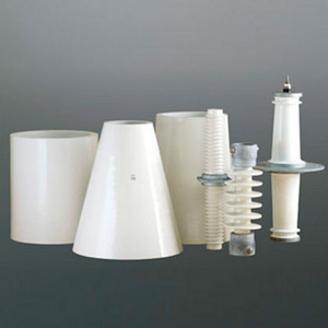
Polymeric insulators consist of a fiberglass reinforced epoxy rod, fittings and a polymeric housing, which for transmission applications is usually made from silicone rubber or EPDM. Functionality and service life of these insulators depends largely on any surface or interface ageing of the polymer material.
Hydrophobicity is an especially critical factor and must be guaranteed over the entire life cycle of the insulator, even when exposed to severe temperatures, high UV, pollution, biogenic contamination and combinations thereof. If hydrophobicity is lost due to ageing, leakage currents can flow through the moistened pollution layer.
At high voltages, electrically sufficient hydrophobicity is assumed given a receding contact angle of approximately 40° or a classification of HC2. But at lower dynamic contact receding angles, significant current can flow through the pollution layer and occasional initial discharges (so-called dry band discharges) can ignite. If such discharges occur over a prolonged period, thermal and chemical damage can occur until the insulator fails.
This edited past contribution to INMR by Professor Stefan Kornhuber at the University of Applied Science Zittau/Görlitz in Germany offered an overview of hydrophobicity test methods and findings.


Key requirements for polymeric materials used in outdoor applications are found in the technical specification, IEC TR 62039. However, in the case of hydrophobicity, there is still no detailed specification since no suitable test method has been available. Long-term research work in Germany aimed to overcome this by testing the hydrophobicity retention and recovery using the dynamic drop test (DDT). In addition, hydrophobicity transfer was analysed using the hydrophobicity transfer (HT) test. Fig. 1 schematically depicts flashover voltage as function of pollution layer conductivity.
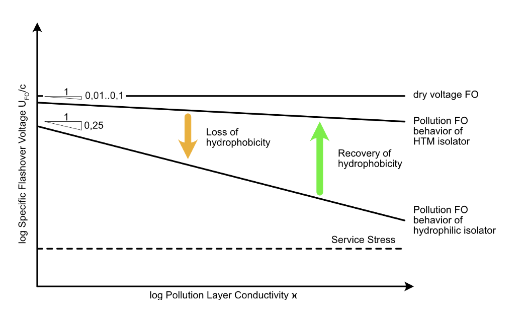
While the pollution flashover exponent for non-hydrophobic insulators is 0.25, in the case of hydrophobic insulators it falls between 0.01 and 0.1. This means less reduction in pollution flashover voltage with increasing conductivity of the pollution layer. Due to different stress and multi-stress situations, the hydrophobicity property of a material can diminish over time, which leads to lower flashover performance from the hydrophobic curve to the non-hydrophobic curve and significantly reduced flashover performance.
Silicone materials also exhibit a certain ability to recover hydrophobicity and insulators in service can revert back to their original hydrophobic pollution flashover performance. Given this, creepage distance reduction factors have been introduced for so-called hydrophobicity transfer materials (HTM). Requirements to be termed HTM include:
• retention of hydrophobicity against certain stresses such as partial discharges under wet conditions (water droplet corona);
• recovery of hydrophobicity after a rest period; and
• transfer of hydrophobicity into polluted surfaces.
Understanding hydrophobic behaviour and the processes that lead to its reduction and recovery is therefore crucial in order to select the proper insulator material and design. Hydrophobicity transfer is already included in the new version of IEC TR 62039 and results of multi-stress testing to investigate hydrophobicity retention and recovery (e.g. the Dynamic Drop Test) have been summarized by CIGRE WG D1.58.
Test Methods
1. Hydrophobicity Transfer Test
In the case of silicone-housed materials in particular, the polymeric structure can be covered by a foreign layer representing pollution. It is known that short and medium-length polymeric chains, i.e. the so-called low molecular weight (LMW) and medium molecular weight (MMW) components, have the ability to penetrate this layer and form a new hydrophobic layer (so-called ‘hydrophobization’). This is particularly necessary to prevent wetting of the layer and thus occurrence of dry band discharges, as described earlier (see Fig. 3).
Testing for this hydrophobicity transfer mechanism has been specified in the new revision of IEC 62039, published in 2021. In principle two different test methods are possible:
• Method A, with quartz powder according to CIGRE;
• Method B. with Kieselguhr according to DL/T 810.
Method A
Test specimens are covered with adhesive foil to obtain a window of 30 mm × 30 mm (L x W). Thickness of these foils defines thickness of the pollution layer and 0.36 mm thickness is to used. Inside the area marked by the foil window, the specimens are coated by applying a slurry made of 7.5 g untreated silica powder (i.e., not silanized, medium grain size of approximately 3 µm) as well as approximately 3.5 ml of a mixture of water and isopropanol (65% water and 35% isopropanol by volume) that has been homogenized by stirring. A clean medical blade is used to wipe off any excess slurry. Since isopropanol tends to evaporate, the slurry is to be used shortly after its preparation. The result is a smooth and even surface.
After application of the slurry, samples are stored for 96h in desiccators under controlled 53% ± 10% relative humidity and temperature of 23°C ± 2°C (e.g. using a saturated solution with magnesium nitrate or a climate chamber).
Method B
The area of the test specimens should be around 30 cm2 to 50 cm2 and their thickness between 3 mm and 6 mm. Polishing test specimens is not permitted before the test. The pollutants include Kieselguhr, in accordance with IEC 60507:2013 Table 2, and NaCl. The Kieselguhr is weighed and put on the surface of each specimen and the NaCl solution is dropped on the Kieselguhr using a pipette or syringe. The Kieselguhr and NaCl solution are mixed and then evenly applied on the specimen using a small paintbrush.
Desired amounts of Kieselguhr and NaCl are 0.5 mg/cm2 and 0.1 mg/cm2 respectively. Mass of Kieselguhr is calculated according to the area of the test samples. The 5 polluted specimens are then placed in a dust-proof container for 96h under standard laboratory ambient conditions (i.e. 40% to 70% relative humidity and 20°C to 25°C).

Evaluation Criteria
Both methods provide results which lead to the same acceptance criteria in regard to the static contact angle from 5 measurements:
• Average value: ≥90°;
• Minimum value: ≥80°.
The criterion is related to static contact angle, which is measurable anywhere across the globe. In addition, several publications as well as IEC 62073 show that the dynamic receding contact angle provides better information in regard to related leakage current behaviour. Dynamic receding contact angle is used in the evaluation and the static contact angle should be measured for conformity with the standard.
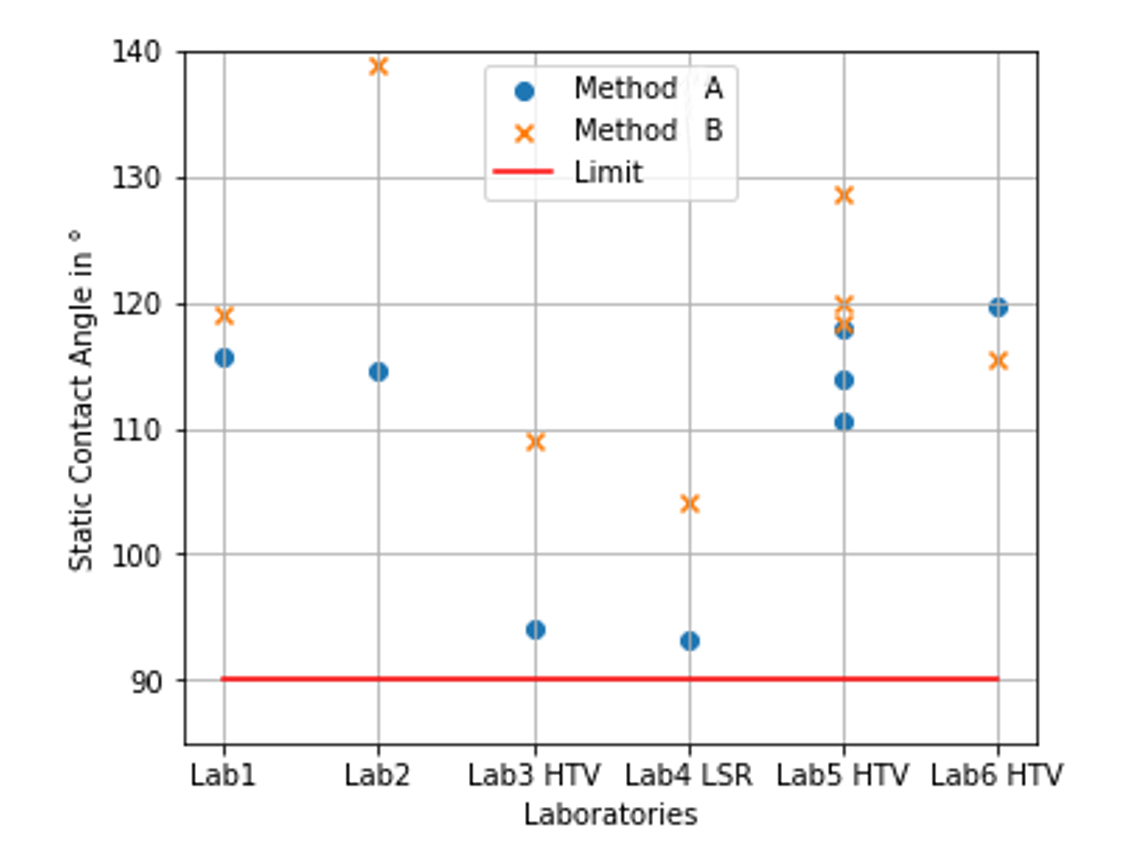
Comparison of Test Results
Several measurements were done at different laboratories to compare test methods during the course of development of the standard and related discussions. Fig. 3 for example compares results of Methods A and B, whereby the values shown are the average mean value of measurements according to the specification.

2. Dynamic Drop Test
Test Method
The Dynamic Drop test (DDT) permits accelerated evaluation of hydrophobicity retention when the surface of a material is subjected to electrical micro-discharges caused by water droplets. This is achieved by supplying an electrolyte with defined volume conductivity and flow rate under simultaneous electric field stress.
Samples are arranged at an inclination angle to the horizontal axis (see Fig. 4). The evaluation criterion is time to loss of hydrophobicity. This stage is achieved when a conductive electrolytic path between high voltage and ground electrodes is formed, which can be detected by measurement of leakage current.
At the beginning of the test, the electrolyte forms discrete droplets that roll down the specimen surface with more or less constant frequency. Presence of the droplet can result in field intensification and hence in ignition of electrical micro-discharges which could lead to localized reduction in hydrophobicity. This process continues until the electrolytic path becomes completely hydrophilic and a wetted path bridges the electrode distance. The failure criterion is reached with increase in leakage current to the mA range.
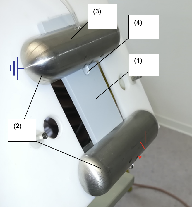
The upper-grounded electrode is supplied with an electrolyte that continuously provides droplets onto its lower side. As such, droplets flow on the surface of the insulation material to the energized electrode at the bottom. As a result of continuous electrolytic and electrical field stress on the drop-off sliding track, its hydrophobicity property is lost.
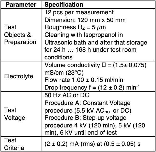
At the start of the test, individual electrolyte residues are formed and increase progressively in number and size. At the end, the number of residues is so high that, in conjunction with a draining drop, a continuous electrolyte connection of both electrodes occurs, which can carry a resistive current. The time taken to reach this state is defined as the retention time (tA) and can be detected by a current measurement system. Table 1 summarizes test parameters during this investigation.

Reference Measurement
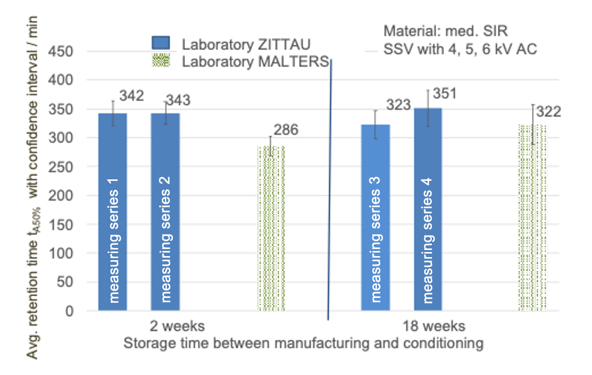
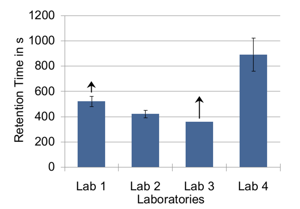
For reference measurement and validation of the test set-up, a special material was found, i.e. the medical silicone, Replisil 22 NO. Not used in high voltage engineering, it is two component curing material at room temperature. Figs. 5 and 6 show initial results with this medical silicone material.
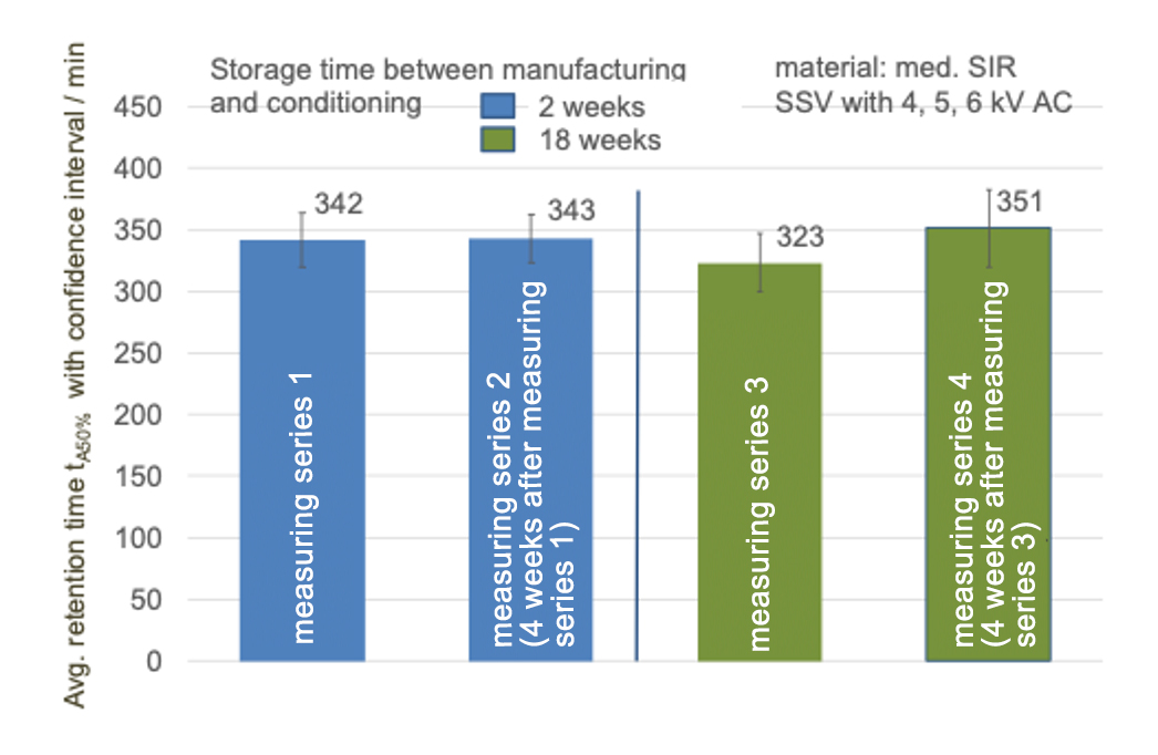
In late 2021 again investigations were done for evaluating the test setups with the same procedure and the same medical silicone, which is shown in Fig. 7.
In summary, the medical silicone Replisil 22 NO seems to show suitable properties for evaluating the test set-up and for comparing measurements. However, once produced, this type of silicone exhibits changing behaviour over time and the same timing must therefore be satisfied.

Summary & Conclusions
The following key properties are necessary for reliable, long-term functionality of composite insulators manufactured with hydrophobicity transfer materials:
• retention of hydrophobicity against stresses such as partial discharges under wet conditions (water droplet corona);
• recovery of hydrophobicity after a rest period; and
• transfer of hydrophobicity into polluted surfaces.
The new version of IEC 62039 includes testing for this hydrophobicity transfer property using two different test methods (A and B), which nonetheless show similar results. However, having two tests for only one property seems not an ideal solution, Moreover, the static contact angle by itself is still not fully representative of behaviour for electrical purposes.
The Working Group behind the new document will now get the first response and experience and, based on this, adjust the next version.
For the Dynamic Drop Test (DDT), CIGRE WG D1.58 has been defining test set-up and the possible evaluation criteria since 2014. After several Round Robin tests, test description and procedure can be recognized and minimum retention time to validate a material have been reached. In terms of subsequent steps, a final brochure will be written and all remaining open questions will need to be solved in a new WG. Moreover, IEC WG 5 decided at the TC 112 meeting in 2019 that this test will soon be proposed as a new work item.
References
[1] Bär, Christiane; Schmuck, Frank; Kornhuber, Stefan; Bärsch, Roland; Brade, Volker: Influence of the Material Composition on the Dynamic Hydrophobicity of Silicone Elastomers for high-voltage Outdoor Application. In: CIGRE Session 2018. Paris, 2018
[2] IEC, TR 62039:2021 Selection guide for polymeric materials for outdoor use under HV stress. 2021.
[3] J. Kindersberger and R. Bärsch, “Schlussbericht zu dem IGF-Vorhaben Prüfverfahren für die Bewertung wasserabweisender Eigenschaften polymerer Isolierwerkstoffe für Hochspannungsanwendungen (IGF-Vorhaben 17001 BG),” Nov. 2015.
[4] C. Bär, R. Bärsch, A. Hergert, and J. Kindersberger, “Evaluation of the retention and recovery of hydrophobicity of insulating materials in high voltage outdoor applications under AC and DC stresses with the Dynamic Drop Test,” IEEE Trans. Dielect. Electr. Insul., vol. 23, no. 1, pp. 294–303, Sep. 2016.
[5] A. Hergert, J. Kindersberger, C. Bär, and R. Bärsch, “Transfer of hydrophobicity of polymeric insulating materials for high voltage outdoor application,” IEEE Trans. Dielect. Electr. Insul., vol. 24, no. 2, pp. 1057–1067, Apr. 2017.
[6] F. Schmuck, “Zur zeitraffenden Alterungsprüfung von Silikongummi-Oberflächen unter Fremdschichtbelastung und simultaner 50-Hz-Spannungsbeanspruchung,” Zittau, Techn. Hochsch., Diss., 1992., 1992.
[7] IEC, TS 60815-4:2016 Selection and dimensioning of high-voltage insulators intended for use in polluted conditions – Part 4: Insulators for d.c. systems, Oct. 2016.
[8] C. Bär, “Bewertung dynamischer Hydrophobieeigenschaften polymerer Isolierstoffe mit dem Dynamischen Tropfen-Prüfverfahren unter Wechsel- und Gleichspannungsbeanspruchung,” München/Zittau, Diss., 2016.
[9] IEC, TS 60815-3:2008 Selection and dimensioning of high-voltage insulators intended for use in polluted conditions – Part 3: Polymer insulators for a.c. systems, Oct. 2008.
[10] Christiane Bär, Roland Bärsch, Alexander Hergert, Josef Kindersberger: Evaluation of dynamic hydrophobicity properties with the dynamic drop test under ac and dc stress and the hydrophobicity transfer test. 19th International Symposium on High Voltage Engineering (ISH 2015_335), Pilsen, 2015
[11] CIGRE WG D1.14: Evaluation of dynamic hydrophobicity properties of polymeric materials for non-ceramic outdoor insulation: retention and transfer of hydrophobicity. Technical Brochure 442, Paris, 2010
[12] Roland Bärsch, Josef Kindersberger, Christiane Bär, Alexander Hergert: Prüfverfahren für die Bewertung wasserabweisender Eigenschaften polymerer Isolierwerkstoffe für Hochspannungsanwendungen, Schlussbericht zu dem IGF-Vorhaben 17001 BG der Forschungsvereinigung Elektrotechnik, München und Zittau, 2015
[13] Alexander Hergert, Josef Kindersberger, Christiane Bär, Roland Bärsch: Stand und Entwicklung von Prüfverfahren zur Bewertung dynamischer Hydrophobieeigenschaften polymerer Isolierstoffe für den Hochspannungseinsatz. Beitrag der 4. ETG-Fachtagung: Grenzflächen in elektrischen Isoliersystemen, Dresden, 2013
[14] Alexander Hergert: Test methods for evaluating the dynamic properties of hydrophobicity of polymeric insulating materials. Dissertation, Technische Universität München, 2017
[15] Hergert, Josef Kindersberger, Christiane Bär, Roland Bärsch: Transfer of hydrophobicity of polymeric insulating materials for high voltage outdoor application. IEEE Transactions on Dielectrics and Electrical Insulation 24 (2017), 1057–1067
[16] Heike Herzig, Stefan Kornhuber: Defined silicone rubber surface structures in a long-term test. IEEE 2nd International Conference on Dielectrics, Budapest, 2018
[17] Cervinka, Rüdiger, Stefan Kornhuber, und Christiane Bär. „Investigation for a reference material for the dynamic drop test (DDT) with a reproduceable and repeatable retention time“. In 2019 IEEE 4th International Conference on Condition Assessment Techniques in Electrical Systems (CATCON), 2019.


