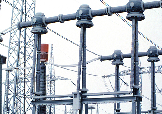
Pollution, ice and snow are all ambient factors that impact the dielectric reliability of post insulators operating at air-insulated substations, especially for HVDC. They also affect equipment that employs post insulators, such as disconnectors and busbar supports.
This edited past contribution to INMR by Eros Stella and Marco Nosilati of GE Grid Solutions in Italy focused on how icing can impact performance of post insulators.


Pollution & Ice
Air consists of nitrogen, oxygen and gases present in much lower concentrations but also includes water vapor in variable concentrations as well as solid particulates of varying composition and dimension. The term ‘air pollution’ is applied whenever substances are present in a different concentration compared to the natural situation. Pollution can be due to human activities that include emissions from factories, thermal power plants, heating systems and transport but can also be linked to natural global cycles involving oceans and volcanoes. Moisture, whatever its origin, only serves to magnify the problem because of the increase in conductivity of the pollution layer. Over the long-term, pollution damages reliability of electrical power systems due to corrosion of key metallic components. In the short term, pollution can decrease performance of insulation on electrical components.
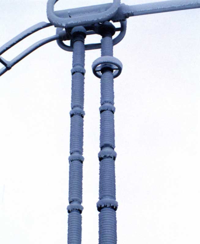
During winter, ice accretion adds to the pollution problem as super-cooled water droplets hit an insulator’s surface. Air temperature and wind velocity together influence build-up as ice and snow accumulate, generally on the windward side of insulators. Growth of icing leads first to mechanical stress on conductors and insulators and later to electrical stress with possible faults or flashovers. Apart from weather, other phenomena also influence the characteristics of icing under energized conditions. These include corona discharges, leakage current, water drop elongation and ionic wind. In particular, corona effects and leakage current have a heating effect while water-droplet elongation and ionic wind have a cooling effect. The sum of all these variables influences morphology of ice and icicles.
There are three distinct types of ice: glaze ice, hard rime ice and soft rime ice. Glaze ice is transparent and has a density of about 0.9 g/cm3. Hard rime is opaque and has a density between 0.6 and 0.87 g/cm3 while soft rime ice is white with density less than 0.6 g/cm3. Hard rime and soft rime icing grows under dry conditions, i.e. water droplets at impact are completely frozen and, since there is no runoff water, no icicles form. Glaze ice grows under wet conditions at 0°C, with formation of icicles.
Pollution Severity & Deposition
Pollution that forms a thick layer on an insulator leads to degradation of its surface resistance. Pollution can be classified as active or inert. In regard to active pollution that forms a conductive layer on an insulator surface, Equivalent Salt Deposit Density (ESDD) is used to quantify level of contamination. This parameter is obtained by measuring the conductivity of the solution containing pollutants removed from the insulator surface and then calculating the equivalent amount of NaCl having the same conductivity, expressed in mg/cm2. Examples of active pollution include gases such as SO2, H2S, NH3, salt spray, bird streamers, sea salt, Na2CO3, ash and cement. Salts have different rates of going into solution such that the higher the solubility the faster they will go into solution. High solubility salts quickly form a conductive layer on an insulator during wetting, but if rain intensity increases so does probability of cleaning the insulator surface. By contrast, if a salt has low solubility it will dissolve more slowly and the quantity of water needed to wash the surface increases.
Non-Soluble Deposit Density (NSDD), the index use to quantify inert pollution deposits, is expressed in weight of non-soluble deposit per unit of surface area of insulator. In the past, it was thought that inert deposits had limited impact on withstand voltage. The greater the inert material deposit, the thicker the water film retained on the insulator surface. As such, the amount of soluble material dissolved in the water film would be higher. More recently, it has been reported that there is indeed an influence of the inert material deposit on withstand voltage of polymeric type insulators.
IEC 60815 identifies two types of insulator pollution: Type A and Type B:
Type A: Solid pollution with non-soluble component is deposited onto the insulator surface and becomes conductive when wetted. This type of pollution can best be characterized by ESDD/NSDD and DDGIS/DDGIN measurements.
Type B: These are liquid electrolytes deposited onto the insulator that have little or no non-soluble components. This type of pollution can best be characterized by conductance or leakage current measurements and is associated with coastal areas where salt water or conductive fog is deposited onto insulator surfaces. Severity for Type B pollution is generally expressed in terms of Site Equivalent Salinity (SES). This is the salinity of a salt fog test that, according to IEC 60507, would give peak values of leakage current on the same insulator that are comparable to those produced at that voltage by natural site pollution, expressed in kg/m3.
Ice Deposition on Insulators
Ice accretion and snow deposition depend on several factors and variables, with intensity established by topographical, meteorological and environmental conditions. Due to the several physical phenomena and electrical factors acting simultaneously on droplets, understanding the characteristics and the accretion of ice on insulators is highly complex. Experiments have been conducted in the laboratory to better understand how energized conditions influence density and other characteristics of the ice.
Atmospheric icing is the consequence of three main processes:
• Hoar frost is caused by condensation of water vapor on cold surfaces;
• In-cloud icing implies freezing of droplets suspended in a cloud on structures;
• Precipitation icing consists of super-cooled droplets that freeze in contact with the surface.
Volume and type of ice depend on several factors, including liquid water content of air, dimension of droplets, air temperature, impact velocity, position and energization of insulators but, above all, shape and type of insulator. Moreover, depending on conditions, ice can be dry or wet. Ice is considered ‘dry’ when the air temperature remains below 0°C, with density mainly a function of impact velocity, median volume of droplets and ice deposit temperature. Ice is said to be ‘wet’ when a film of water is present on the insulator surface. Accreted ice is then called ‘glaze’. If there is run off water, icicles form, especially on the windward side, and bridging of any sort represents a hazard.
Ice morphology defines crystal size and shape. When water molecules stabilize, the special lattice of ice leads to hexagonal symmetry of snowflakes. Electrons pass through the bulk and across surface layers and, in the presence of contaminated ions, form a shorter and weaker flashover path than normal.
Glaze ice is generally produced when raindrops pass a layer of air that is above 0°C. During this passage, heat exchange from raindrops of relatively large diameter, (i.e. 100 µm), leads to ambient super-cooling. Just as the raindrops hit the insulator surface, a certain mass, dm, will freeze. In 1974, Hobbs calculated the expression of dm/m as follows:
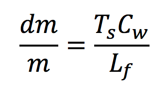
where m is the mass of raindrop, Ts is drop temperature (lower than 0°C), Cw is specific heat of water(1 cal/g) and Lf is latent heat of fusion water (79.7 cal/g).
Size of water drops has great impact on type of ice that forms. For example:
• droplets of 15 µm mean diameter form opaque white ice of density 0.4-0.6 g/cm3;
• droplets of 50-80 µm mean diameter do not fully freeze upon contact, so ice caps and icicles appear;
• droplets of even greater mean diameter result in ice with 0.87-0.9 g/cm3 density that has excellent adhesion to most surfaces.
The lattice structure of ice gives it a high degree of stability, as demonstrated by its high latent heat of melting (8987 J/mol) and also high latent heat of sublimation (50.911 J/mol). Masaori Hara and C. Luan Phan, in tests carried on in a cold room, found that ice density and type vary with decreasing temperature and proposed a classification into 4 regions:
Region I → -9 ≤ T < 0℃
Transparent glaze ice covered by water film is formed.
Region II → -12≤ T < -9℃
Within this span, three steps are observed: the first is similar to Region I; the second see ice grow more slowly while the water film continues; and the last being formation of a transparent hard rime ice covered with opaque ‘shrimp tail-like’ ice.
Region III → -19 ≤ T < -12℃
Ice is opaque hard rime with a transparent glaze ice on the surface of insulator skirts. Here, super-cooled droplets freeze instantly on impact with the surface, contributing to increasing ice thickness.
Region IV → T< -19℃
Ice is soft rime with a layer of clear ice on the surface of insulator skirts.

Analysis of Leakage Current on Iced Insulators
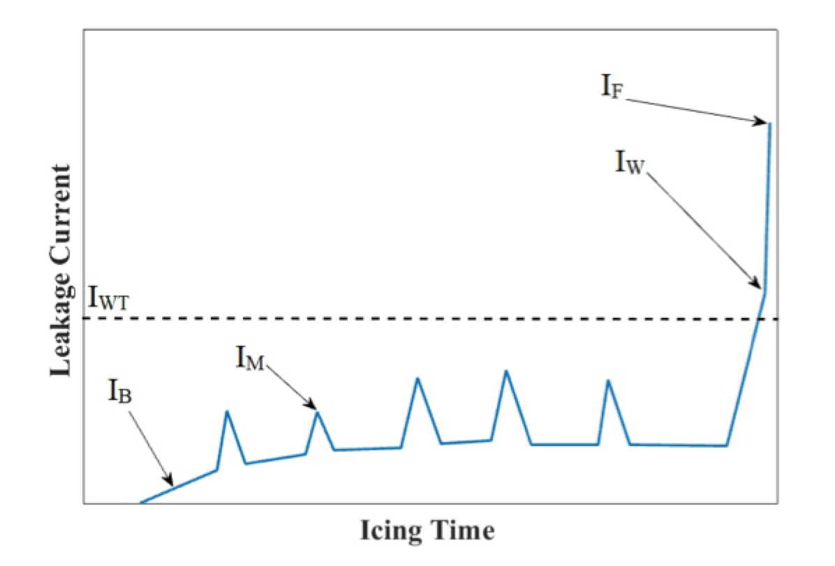
Leakage current (LC) is an efficient parameter to monitor the insulator flashover process since it is relatively simple to measure, even under outdoor conditions. As part of LC analysis of iced insulators carried out in the late 1970s by Masaori Hara and C. Luan Phan, tests were performed on long rod polymeric as well as cap & pin porcelain insulators set in the cold room at the University of Quebec in Chicoutimi. LC on long rod polymeric insulators was studied as the superposition of four components: the basic one, called basic leakage current IB, is almost constant in amplitude. Then, there are peaks in amplitude responsible for melting the ice and referred to as melting current, IM. When IM is below a certain threshold (about 18 mA and stated as IWT), corona streamers become visible. When a white arc appears over some insulator skirts, IW current is flowing and this has a peak magnitude greater than the threshold, IWT. Finally, when flashover occurs, the arc completely bridges the extremities of the insulator and current, IF, flows through the leakage path. As can be seen, amplitude of IF is greater than for IW.
One observation that helps to better understand the flashover phenomenon is that amplitude of leakage current depends on the balance of melting and freezing, i.e. ice accumulation. The greater the melting rate versus the icing rate, the greater the quantity of ice that melts and produces a water layer that leads to flashover.
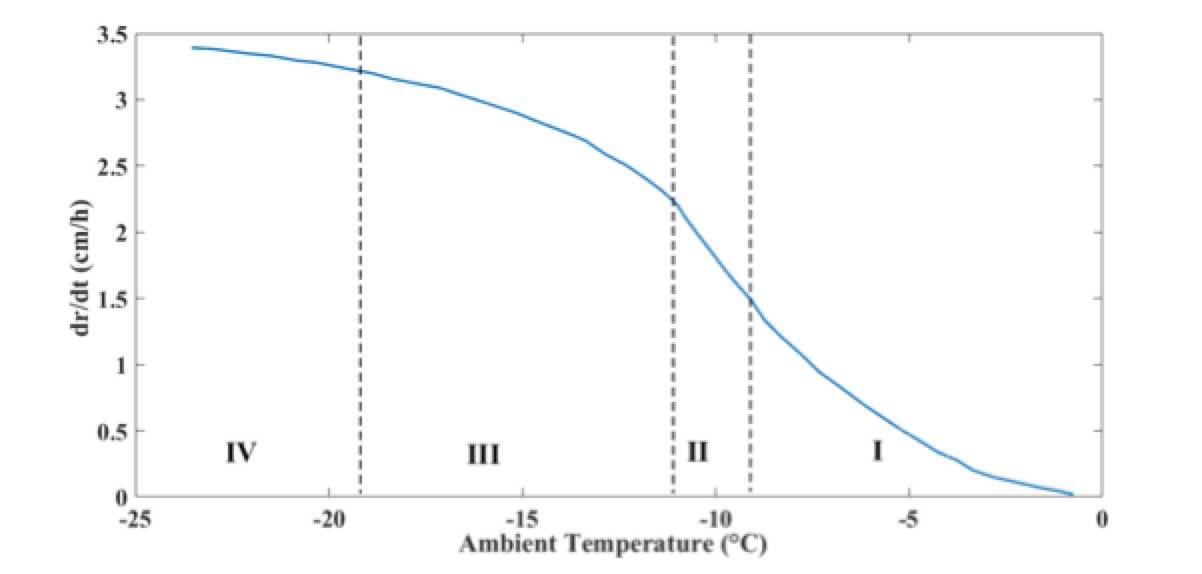
Basic current, IB, does not have sinusoidal shape but rather is composed of small streamer impulses occurring between larger streamer pulses of about 2 ms. Negative pulses are sometimes greater in amplitude with respect to positive pulses. IB increases with decreasing temperature in Region I, as described above, when temperature drops from 0°C to -9°C. This could be explained by the balancing of melting and icing rates. Fig. 3 shows rate of icing accumulation in relation to ambient temperature. During the first period, in Region I, ice continues to grow almost linearly, which means that freezing balances melting. When temperature reaches the boundary between Regions I and II, IB magnitude is at its maximum. From this maximum, going toward lower temperature, IB magnitude decreases in Region II until becoming virtually negligible in Regions III and IV.
Another important aspect discovered during past research was the independence of IB from applied voltage. This can be explained by the fact that electric field is related to total gap length, which in this case is the sum of the distances of icicles tips from the upper surfaces of insulators skirts. Since this total length is constant in Region I and also in the early moments of Region II, electric field remains constant. Melting current, IM, is measured principally in Region II because water film disappears and therefore icicles are not formed. When a discharge occurs, current tends to spike.

This process is the result of melting due to increased leakage current and resulting growth in conductivity of the ice mix to water layer. As a consequence, water dripping off gives rise to strong corona streamers at the tips of icicles. As icicles begin to melt under the effect of discharge, air gaps lengthen and the discharge weakens. Therefore, IM depends on type of ice and applied voltage. The lower the temperature, the higher will be the peak in melting current. Average value of IM is highest in Region III and for this reason it can be supposed that the probability of transition from melting current to white arcing is more elevated than in other regions. In Region IV, due to high resistance of the ice layer and to absence of a water layer, IB is zero while IM does not occur at all.
When white arcing begins, current, IW, is assumed to have a magnitude greater than IM and the waveform is almost sinusoidal. Moreover, IF is significantly greater than IW. The threshold for flashover current, set at 120 mA for polymeric long rod insulators, does not change for different types of ice and is independent of temperature during icing periods. In the case of porcelain insulators, this value is set at 180 mA.
Two different remedial actions are possible: one is monitoring contamination severity; the second is preventing flashover. Researchers have investigated correlation of LC and magnitude of its harmonic components with probability of flashover. For example, LC on porcelain station post insulators has been analyzed under glaze ice conditions – considered the most dangerous type of flashover. The parameter considered in this regard is LC envelope, computed by taking the peak positive LC value over one-second intervals. This is regarded as useful since it is not affected by partial discharge activity or by formation of air gaps.
Two stages have been identified: Stage 1 is characterized by a quasi-constant LC of magnitude less than 1 mA. The low current is due to presence of capacitance between the insulator and the tips of icicles where corona discharge activity is present. This period of Stage 1 is termed ts. The waveform during the first stage is almost sinusoidal, however low magnitude harmonics are also present. These are caused mainly by electromagnetic interference, corona discharges and background noise in the data acquisition chain. Third and fifth harmonics are those having greater amplitude.
At the transition from Stage 1 to Stage 2, waveform completely loses its sinusoidal shape. Consequently, in addition to harmonics, a DC component appears due to asymmetry in positive and negative peaks. During increase in leakage current, i.e. when partial arc discharges take the place of intermittent discharges, the waveform first returns to almost sinusoidal shape with a non-negligible third harmonic due to voltage passing through zero during extinction and re-ignition of the partial arcs. As electric arcing becomes more intense, leakage current deviates from a sinusoidal shape and amplitude of harmonics increases.
There are basically 3 methods proposed for rate accumulation monitoring: one based on measuring the third and fifth harmonics variation of LC; a second based on ratio of rms value to maximum value of LC; and, in cases where ice accumulation rate does not affect LC amplitude, a recommended phase shift method. The goal of these kinds of monitoring systems is to measure ts, which corresponds to the period of formation of critical length icicles. The shorter the value of ts, the greater the accumulation rate on the insulator and the higher the probability that this will lead to flashover.
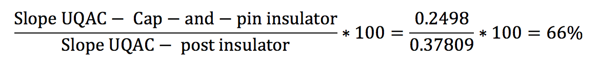
To investigate the possibility of predicting flashover by monitoring the harmonic components (based on the idea that harmonic components generally increase only during arcing), researchers in Iran developed the argument that the third and fifth harmonics are the objects of monitoring activity. When an insulator is clean or only lightly contaminated, amplitude of the 5th harmonic is typically larger than the 3rd. But when contamination level grows progressively, this behavior switches and the 3rd harmonic becomes greater than the 5th. The non-linear impedance of surface contamination is the reason behind this increment and therefore a K5/3 index has been introduced, as follows:
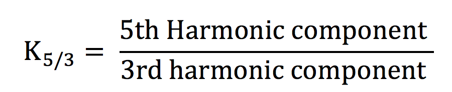
When K5/3 is higher than 100%, i.e. numerator greater than denominator, the insulator is clean. If the index is lower than 100%, the insulator operates under polluted conditions. When K5/3 < 30%, the insulator is in a critical state and there is a 90% probability that flashover will occur within two minutes. The real value of this methodology lies in the fact that it can be used for any type of insulator.

Ice Testing on Station Post Insulators
The scope of the following analysis is to validate what has been discussed above with specific reference to station post insulators. Unfortunately, published literature on this is limited because of the difficulty accessing test data and parameters that characterize the behavior of these insulators.
This type of analysis can be conducted either in field or in the laboratory. Regarding field experience, the first step is selecting a time period to record data on climatic conditions and environmental parameters, e.g. from one to two years. The next step is examination of data collected. Since a long period is needed for this approach, laboratory investigation is an alternative that allows a shorter time interval yet still with relatively good accuracy. While not as realistic as field investigation, it offers positive features such as a wider range of test cases and, above all, repeatability. The final goal of such investigations is proper dimensioning of the insulators for critical service situations, e.g. DC systems exposed to icing. In this case, laboratory testing consisted of:
1. Determination of maximum withstand voltage of 3 kV and 82 kV porcelain post insulators under icing conditions (performed at the University of Quebec in Chicoutami (UQAC), Canada).
2. Full-scale testing of 370 kVdc post insulators for application on disconnectors operating in polluted/icing conditions (performed at STRI in Sweden).
Determining Maximum Withstand Voltage Under Icing
This ice/pollution test, carried out at UQAC by Masoud Farzaneh and Fanghui Yin, was performed on two different insulators. A peculiarity of this test that makes it different from others is use of the ‘up-and-down’ method to determinate maximum withstand voltage. This method can be used in situations where withstand voltage of the insulator under investigation is not yet clearly defined. The two insulators under test in this case included:
• a ceramic post insulator (C8-750) composed by a single unit, with a minimum creepage distance of 4250 mm and an arcing distance of 1520 mm, i.e. a creepage factor of 2.79.
• a ceramic post insulator (C8-250) composed by three units, with a minimum creepage distance of 1200 mm and arcing distance of 400 mm per unit, i.e. a creepage factor of 3.
The nominal voltages of the two were 82 kV and 9 kV (3 kV per unit) respectively.
Type of ice is a fundamental parameter when evaluating flashover voltage of insulators and, in this test, glaze ice was chosen since it is the most critical. Before the icing procedure, the insulator was contaminated with a salt deposit density of 0.12 mg/cm2 using a mixture composed of 40 g of kaolin, NaCl and 1000 g of de-ionized water (following the solid layer method described in IEC 61245). Before application of this layer, insulators were carefully washed from dust and oil residue.
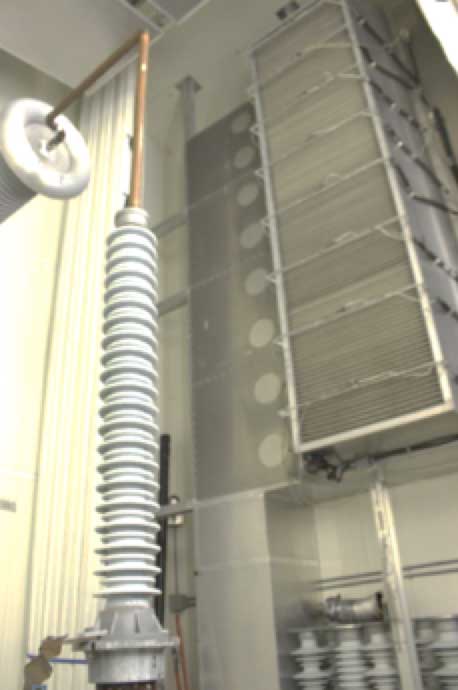
The climate chamber at UQAC’s Icing Research Pavilion, measures 6 m x 6 m x 9 m and contains a cooling system, a water spray system and a wind generation system, as prescribed in IEEE 1783-2009 (see Fig. 4). The distance between the spray and wind system and the vertical axis of the test object was 3 m, as per IEC TS 61245. Conditions inside the climate chamber were as follows:
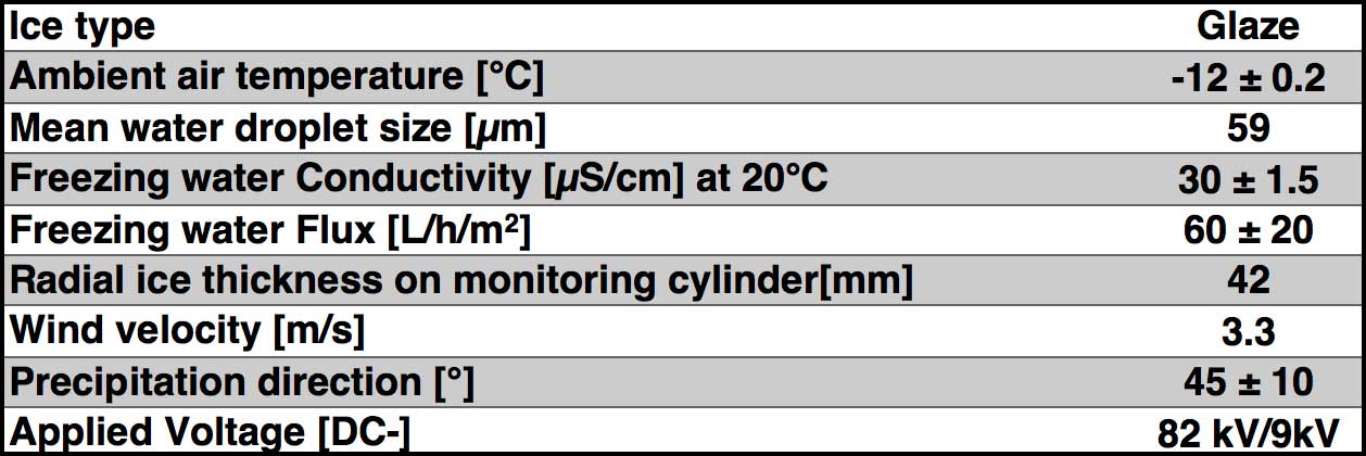
IEC TS 61245 describes the procedure for determining degree of pollution on an insulator surface with the aid of a wet cloth. At least three consecutive wipes of the surface are performed. The deposit collected is then dissolved in a specific quantity of de-ionized water, i.e. 2 or 4 liters per square meter of surface. Salinity and SDD are calculated using the following:
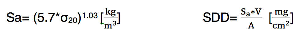
where V is the volume of the suspension, expressed in cm3 and A is the surface area of the insulator, in cm2.

The process for determining withstand voltage is divided into the following steps:
1. after contamination, the insulator is dried for 8 hours before icing;
2. the climate room is cooled to -12°C;
3. DC- service voltage (V0) is applied to the insulators and spraying systems and fans are turned on simultaneously;
4. When ice thickness reaches 42 mm on the rotating monitor cylinder, service voltage is turned off;
5. After a short period, Δt0, the spraying system is turned off;
6. Voltage is re-applied on the covered insulator at a rate of 3.9 kV/s until an estimate VF value is reached;
7. Voltage is maintained constant for 15 minutes or until flashover occurs;
8. To confirm withstand voltage, VWS, the process is repeated.
If flashover occurs, the up-and-down method is performed once again in steps of 5% less than the initial voltage. Specified withstand voltage is confirmed if no flashover occurs during three consecutive tests at the same voltage level and two flashovers occur at a voltage one step higher.

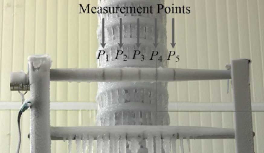
Ice-thickness is measured in a rotating cylinder at 1 rpm facing the direction of precipitation (see Fig. 6).

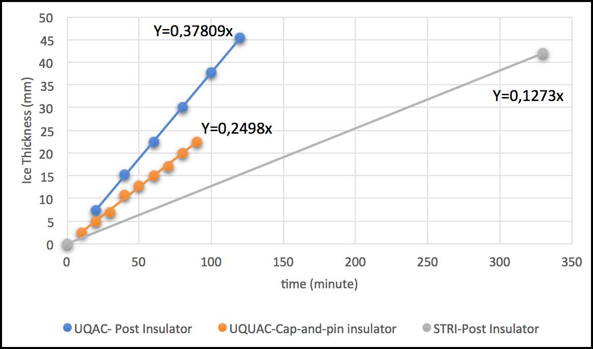
Ice accretion follows a linear function with respect to time. Fig. 7 shows the difference in ice accretion between a post insulator and the cap & pin insulator. The straight line of the cap & pin has smaller slope than for the post insulator while, during testing at STRI, this rate of ice accretion was even smaller.
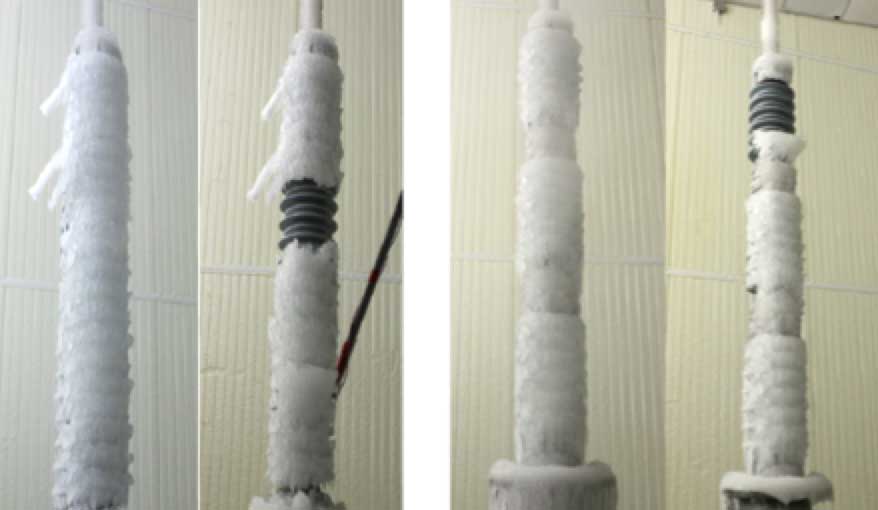
Another important consideration was that, this since this was a pollution and icing test, water conductivity also had to be measured. During withstand tests, ice melts due to the Joule effect and dripping water was collected by three rows of cups placed below the test object, each with a volume of 100 mL. It should be noted that not the entire ice on the insulator melts but rather only specified sections defrost. In the case of the C8-750 post, melted area was set at 40% of its total height whereas for the C6-250 post the melted area was immediately in proximity to the energized electrode (see Fig. 8). Fig. 9 shows water conductivity measured for these two test objects.
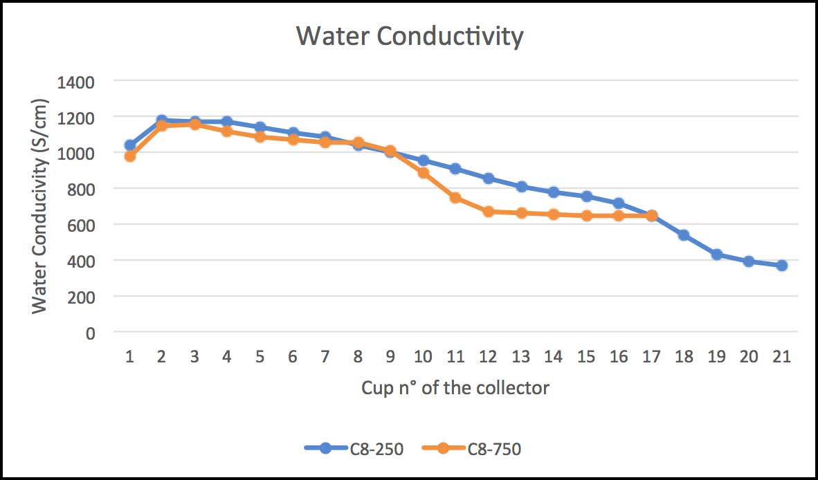
It is worthwhile to note that water collected in the first cups had greater conductivity versus that falling into the last cups. This suggests that, during the ice accretion process, ESDD tends to rise on the external layer of water due to different densities of water and ice. As the ice starts to melt, ESDD decreases as sheds are progressively cleaned. Maximum withstand voltages at the end of the test were as follows:
C8-750 → Vws = 110 kV V0 = 82 kV Vws 1.5 V0
C8-250 → Vws= 68 kV V0 = 9 kV Vws 6.5 V0
These results confirm means that the test insulators are sufficiently dimensioned for withstand service voltage. Since C8-250 seems greater than needed, a shorter version could also be considered for this application.
Full-Scale Performance Test of 370 kV DC Post Insulators for Disconnectors Under Polluted Icing Conditions
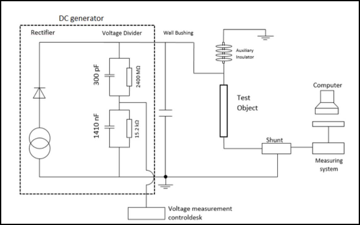
The object under test in this case was a porcelain post insulator (C12.5 > 2550) composed of 3 units and with 27,292 mm minimum creepage and 7250 mm arcing distance, i.e. a creepage factor of 3.76. This was a combined pollution and ice test with the solid layer method and where the reference standard is IEC TS 61245. As in the test described above, target SDD was 0.12 mg/cm2 and 0.1 mg/cm2 for NSDD. Preparation of the test objects was the same. The insulator was installed in the chamber at -10°C and water sprayed on until ice thickness on the monitoring cylinder reached 1 to 2 mm. The object was then energized at -370 kV dc.
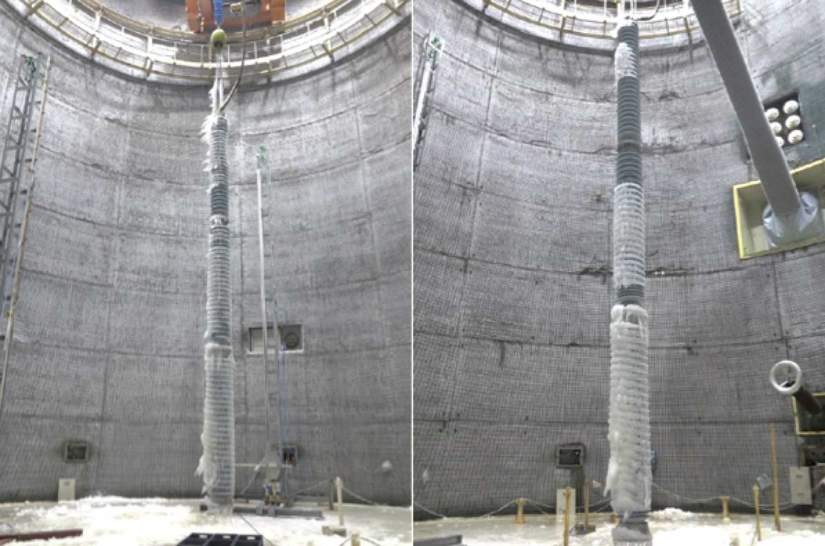
This was maintained until ice thickness reached 42 mm at which point voltage and spray system were turned off, in that order. The ice was left to chill and harden at a constant -8°C. The withstand test was then performed at the same voltage as during the ice accretion period while temperature inside the chamber was raised progressively from -10°C to +3-5°C at a rate of 1 to 3°C/h using steam. The test stopped when the ice melted, and leakage current had decreased in amplitude to the point where flashover was no longer possible. Test set-up was as shown below in Fig. 11. At the end of the test, it was confirmed that the maximum withstand voltage at the value of 0.12 mg/cm2 of ESDD was 370 kVdc negative polarity.
Design Strategies for Proper Ice Dimensioning of Station Post Insulators
The solid layer method along with icing tests together allow combined icing/pollution testing. This type of situation is more critical than for other post insulator applications and the reason why required creepage factor must be greater than 3.5 to assure desired withstand voltage. It should be noted that ice accreting on an insulator surface itself represents a class of pollution and in this respect does not differ from salt or other contaminants. Type of ice is also fundamental. Glaze ice, for example, which is thick and opaque, is the worst case. Also to be considered is whether icicles are present since these pose an additional hazard that must be taken account of. One risk, however, is to overstate dimensions. In fact, during laboratory tests carried out with a certain type of ice, the worst case was assumed, i.e. glaze ice, and therefore introduced conditions that could lead to overestimation – especially since the security coefficient is already high.
If presence of icing results in lower surface resistance while, at the same time, leakage current increases, there is higher probability of flashover. This might induce a power system operator to select a larger insulator. It is therefore important that test conditions rigidly follow what the standards dictate. The tests described above, for example, involved changes in solid layer density between the two test laboratories. Also, ice accretion was carried out at different temperatures. At STRI, ice was accreted at -8°C while at UQAC this temperature was set at -12°C. Standard IEEE 1783-2009 does not specify a fixed accretion temperature but rather suggests a range anywhere between -15°C and -5°C.
It is possible that, at such low temperatures, salt on an insulator surface does not dissolve with water during the ice accretion phase. The more NaCl dissolves in solution, the more conductivity increases, meaning lower surface resistance. It can be implied that the lower the temperature in the climate chamber, the faster the transition from liquid water droplets to ice and the less time needed to dissolve the salt into solution. To better appreciate what this might mean with regards to over-dimensioning, the creepage factors and USCDs used during the icing/pollution tests described above were compared to respective values calculated using parameters provided by IEC 273 for pollution Classes I and Il.
As shown below, there is substantial spread among these values. For example, insulator C12.5-2550 is 2.2 times the CF calculated using a Class I creepage distance – a high coefficient. A good coefficient lies between 1.4 and 1.7 times that calculated for pollution and should be sufficient to resist even the worst outdoor conditions.
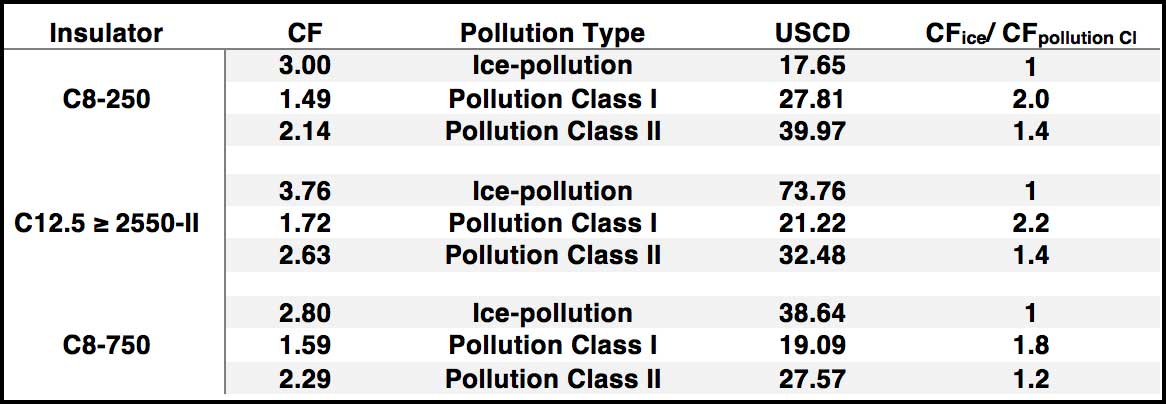
Fig. 12 shows trend in creepage factor from 0 to 42 mm thickness of ice. Values at 0 mm thickness are calculated with the AC equivalent dimensions reported in IEC 60273. For simplicity, it has been assumed that insulator behavior under AC and DC conditions represent the same level of criticality.
From these tests, it was verified that the accretion trend is linear. For purposes of dimensioning, it is possible to start with standard IEC 60273 to allow initial dimensioning of suitable height and creepage distance. Then, CF should be calculated, which is related to the specific pollution level, e.g. Class I or II, depending on the case under study. CF related to icing is arrived at by multiplying CFpollution by some security coefficient that varies from 1.4 to 1.7, as stated above. This parameter should then provide for a first criterion for dimensioning. Furthermore, using other values, it also becomes possible to establish the slope with the goal of calculating suitable CF at any fixed ice thickness.
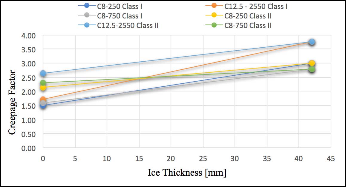
Fig. 13a shows how the C8-250 post insulator has been dimensioned using this method:
CF calculated for Class II pollution: 2.14
CFMax for icing conditions = 2.14 x 1.7 = 3.6
CFMin for icing conditions = 2.14 x 1.4 = 3
CF should be selected inside the area between the solid red line, representing CFmax for icing conditions and the blue line, representing the CFmin for icing.
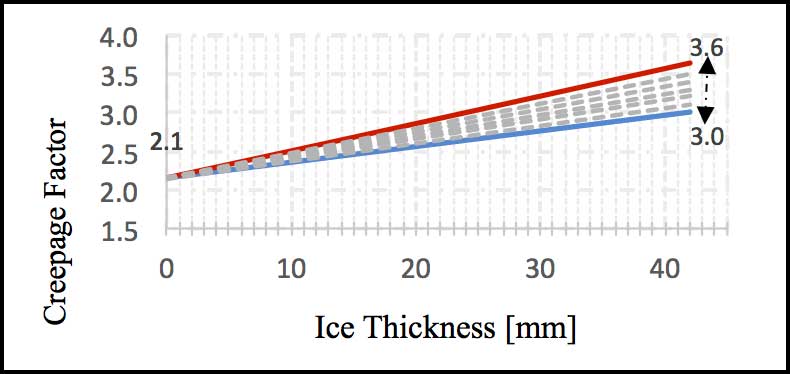
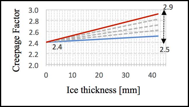
Fig.13b shows this same methodology applied to C12.5 ≥ 2550 in the case of Class I pollution, using these suggested criteria. The range of possible CFs falls between 2.5 and 2.9, i.e. lower than what was used during laboratory testing.
Conclusions
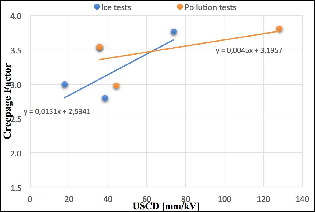
The most significant parameter for this kind of evaluation is creepage factor (CF), namely the ratio between creepage distance and arcing distance of the insulator under consideration. While the literature offers a lot of dimensioning criteria when it comes to overhead line insulators, little has been published when it comes to station post insulators – the objects of this study. Combining the solid layer method with icing allows ice/pollution testing, a situation that is more critical than pollution alone. For this reason, appropriate creepage factor is higher than 3.5 to obtain desired withstand voltage. Fig.14 shows the trend line of creepage factor versus USCD for insulators under ice and pollution testing. The slope of the icing test trend (blue line) is higher than that for pollution (orange line). This means that dimensioning for icing conditions is more critical in comparison with for pollution. Further investigation of iced/polluted insulators is suggested to validate the dimensioning factors at different levels of ESDD of ice. Moreover, ice testing under real field conditions and studying leakage current is recommended to better understand real contamination issues. Recording environmental parameters will also help determine if the assumptions in the standards are correct in accounting for natural variability.
Further investigation is also suggested to obtain information and validation of this parameter. It would also be interesting repeat the same on polymeric post insulators to better understand correlation with leakage current. Finally, comparison with AC voltage at same icing level would be useful to define the most common service situation and to learn if this is less severe than for DC under exposure to pollution.
References
[1] CIGRE Task Force 33.04.01, Polluted Insulators: a review of current knowledge, 2000
[2] Farzaneh Masoud – Chisholm William A., Insulators for Icing and Polluted Environments, 1. Aufl., US, Wiley-IEEE Press, 2009. (IEEE Press Series on Power Engineering).
[3] Farzaneh M, Kiernicki, J., Flashover Problems Caused by Ice Build-up on Insulators, “EI-M”, 11, 2 (1995), p. 5-17.
[4] Masoud Farzaneh, Atmospheric Icing of Power Networks, Atmospheric Icing of Power Networks, Springer Netherlands, 2008
[5] IEC/TS 60815-1, Edition 1.0, 2008-10
[6] Jiang Xingliang , Guo Yujun ,MengZhigao, Additional salt deposit density of polluted insulators in salt fog, “IET Generation, Transmission & Distribution”, 10, 15 (2016), p. 3691-3697.
[7] Svein M. Fikke, Jan E. Hanssen, Lars Rolfseng, Long range transported pollutants and conductivity of atmospheric ice on insulators, v. 8.
[8] Looms J. S., Insulators for high voltages, 7. London, Peregrinus, 1988
[9] Jingyan Li, Caixin Sun ,Wenxia Sima, Contamination Level Prediction of Insulators Based on the Characteristics of Leakage Current, “TPWRD”, 25, 1 (2010), p. 417-424.
[10] Influence of Ice and Snow on the flashover performance of outdoor insulators – part I: effect of ice; 1999
[11] Makkonen Lasse, Models for the growth of rime, glaze, icicles and wet snow on structures, “Philosophical Transactions of the Royal Society: Mathematical, Physical and Engineering Sciences Vol.358, 2913 – 2939”, (2000),
[12] Mizuno Y., Kusada, H., Naito, K., Effect of climatic conditions on contamination flashover voltage of insulators, “T-DEI”, 4, 3 (1997), p. 286-289.
[13] Hara M. – Luan Phan,C., Leakage Current and Flashover Performance of Iced Insulator, “IEEE Transactions on Power Apparatus and Systems”, PAS-98, 3 (1979), p. 849-859.
[14] Hara M. – Luan Phan,C., A study of the leakage current of H.V. insulators under glaze and rime, “CEEJ”, 3, 3 (1978), p. 15-22.
[15] Meghnefi F. Volat, C., Farzaneh, M., Temporal and Frequency Analysis of the Leakage Current of a Station Post Insulator during Ice Accretion, “T-DEI”, 14, 6 (2007), p. 1381-1389.
[16] Kordkheili Hadi Hosseini – Abravesh,Hassan – Tabasi,Mehdi, Determining the probability of flashover occurrence in composite insulators by using leakage current harmonic components, “T-DEI”, 17, 2 (2010), p. 502-512.
[19] R.Rudervall – J.P. Carpenter, R.Sharma, High Voltage Direct Current (HVDC) Transmission systems technology review paper; Washington D.C, 2000 (Energy Week 2000).
[20] Ryan Hugh M., High Voltage Engineering and Testing, 2, Stevenage, IET, 2000. (Power and Energy).
[24] M.Farzaneh,F.Yin ,Determination of the maximum Withstand Voltage of 3 kV and 82 kV Porcelain Post Insulator under Icing Conditions, University of Quebec á Chicoutimi, October 3 2016
[25] D.Windmar,F.Ungsgard, Full Scale performance test of 370 kVdc post insulators,for disconnector,in polluted/icing conditions, STRI AB, 12-30 May 2016
[26] M.Brosch, J.Bolech, J.Lachman, Test report No:10667/A/17, EGU HV laboratory a.s ,8 June 2017
[27] M.Brosch, J.Bolech, J.Lachman, Test report No:10667/B/17, EGU HV laboratory a.s ,8 June 2017
[28] W.Manzke, Dr.Ing. H. Jahn, Test Report No: H16011,3-4 February 2016
Photos: GE Grid Solutions