Bushings represent a significant expenditure and have a profound impact on power transformer and reactor reliability. Since thermal, electrical, and environmental stresses, among other factors, place high demands on them over their life cycle, these must aways be considered when evaluating their condition.
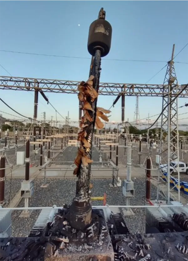
One of the main bushing technologies, with very large numbers of units in service worldwide, is that with oil-paper internal insulation, commonly known as OIP type. This design makes this component vulnerable to sudden catastrophic failure of an explosive nature that, while rare, can seriously impact surrounding equipment at a substation.
Currently, life expectancy of transformers in Colombia is increasing, exceeding the 40-year values initially considered as reference. At the same time, bushings, due to possible failure risks they can present and their collateral impact, can reduce life expectancy and reliability of power transformers and shunt reactors. Therefore, it is critical to establish a proactive evaluation strategy to replace this important component whenever deemed necessary.
According to an analysis by CIGRE 642 (Transformer Reliability Survey), one of the main causes of transformer failure are the bushings. For example, bushings accounted for 14.4% of total transformer failures observed across all voltage ranges. Moreover, 47% of bushing failures carry a serious consequence: fire (30.4%), explosion (10.4%), leakage (5.2%) and collateral damage (0.9%). As such, condition assessment and replacement of faulty bushings can dramatically reduce risk of transformer failure. While replacing degraded bushings proactively will extend the life expectancy of the transformer, another benefit comes from reducing carbon emissions since more than 60% of the tons of CO2 are generated during the manufacture of new transformers.
The evaluation strategy for this component at ISA INTERCOLOMBIA has traditionally been limited to condition-based maintenance considering evaluation of power factor and capacitance parameters as well as operational inspection reports. Now, after an exhaustive evaluation of bushing failure modes (e.g. Paper ID 11187 A2 Power transformers and reactors PS2 – Advances in Transformer Analytics presented at the 2024 Paris Session) as well as benchmarking of maintenance practices for this component, a predictive evaluation methodology has been developed that allows early identification of risk patterns of failure, allowing inputs to define a program of proactive replacement.
Since the life expectancy of bushings can be less than that of the transformer itself, carrying out proactive renewal helps guarantee reliability. One challenge, however, is that establishing a universal renewal age for transformer bushings is impossible given that there are considerable variations in weather conditions, operating characteristics, load profiles, maintenance criteria and manufacturer that can all greatly impact a bushing’s condition. Carrying out too early renewal could represent financial loss in the life of the asset while too late renewal implies greater risks and possibly decreased reliability.
For this reason, work was carried out that focused on defining the treatment given to bushings of power transformers and reactors in the last stage of their life cycle. Strategic guidelines were defined on which decisions will be made to help guarantee reliability of equipment through a renewal strategy. Early identification of risk factors also allows prioritizing bushing renewals, considering all the strategic aspects of their management.
This edited contribution to INMR by Elkin Cantor of ISA INTERCOLOMBIA proposes an approach for proactive management of bushings to ensure more reliable power transformers and reactors.

Energy consumption is increasing globally every year as part of the electrification and energy transition, power transformers and reactors play an important role in powering the increase of energy demand, a high reliability is more and more in demand. To meet this high reliability, it is important to have an effective maintenance strategy. Midlife refurbishment is a process to improve or extend the lifespan for the transformer and sustain the same performance and reliability. Most activities in this process are focused on preserving the condition of the active part. While this is reasonable since the main driver to decide on renovation of a power transformer is condition of the active part, sometimes it can be overlooked that some components may be ageing faster than the active part.
Bushings are among the most critical components of a power transformer and reactor. Regular bushing maintenance (cleaning, measurement, and oil sampling) which is in the scope of OPEX is not part of life extension solutions. Only replacement, which is in the scope of CAPEX, is part of a life extension program. However, the conditions of degradation of a bushing can be different for each unit even if they are the same age. One may be in better condition compared to another of the same age; another could be in a worse condition. The challenge is that having a universal renewal age for bushings in power transformers is impossible. This is because there is a considerable variation in weather conditions, operating characteristics, load profiles, maintenance criteria and manufacturers – all of which can greatly impact condition of a bushing.
Performance and reliability of an asset is influenced by inherent reliability (how it was designed), the operational environment (how it has been operated) and the maintenance plan (how it is been maintained). Those aspects were considered in a comprehensive evaluation methodology developed to define and prioritize renovation of bushings.
According to behavior of different parameters such as age, historical electrical stress, design, and evolution of diagnostic tests, bushings are prioritized by assigning them a risk level on a scale of A (high), B (Medium) and C (Low). This allowed structuring a renovation plan projected until 2033. In total there would be 91 bushings, a very large job that would be impossible to carry out in a single year. Therefore, prioritization made it easier to structure a medium-term plan.
Bushings are an important element for the reliability and extension of the useful life of the transformers and reactors, given the collateral impact that they can present in case of failure.
It has been evidenced that the life expectancy of bushings may be slightly shorter than that of the transformer. Carrying out timely renewal will help ensure reliability of transformers and reactors. Although bushing monitoring tools exist, the various potential failure modes go beyond only electrical issues. That is why it is important to carry out a comprehensive evaluation of their condition to define a timely renewal strategy.
Renovating bushings can be a great challenge. For example, changing them in some cases might require custom units since the dimensions of the bushings differ by year and manufacturer. The useful life expectancy of a transformer must not only analyze the condition of the active part but also one of its main components – the bushing.

Bushing Technologies
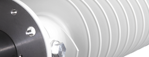
A transformer bushing is a device through which the connection between a switchyard and a transformer winding is achieved. The bushing conducts current through an internal conductor and provides insulation between this conductor and the tank.
Different kinds of classification could be applied to bushings, such as by type of core insulation, outdoor end housing, and terminal transformer end housing. For this discussion, the main characteristic of the technologies of bushings are based on the core insulation as are presently in operation at ISA INTERCOLOMBIA.
1. OIP (Oil-Impregnated Paper)
High voltage bushings these days are condenser type – also known as fine-graded or capacitance-graded. The condenser core is made from oil-impregnated kraft paper insulation inside an oil-filled shell. It is designed to reduce field stress and optimize field distribution into the core insulation when passing through a grounded transformer tank.
OIP bushings generally have an upper air side and a lower oil side with porcelain or polymeric insulators. The key advantage of OIP bushings is their lower cost since this is a well-established design technology. The main disadvantages relate to risk of fire and environmental issues. This is because, during bushing failure, very high temperatures are reached that exceed the ignition point of the mineral oil used as part of the core insulation. Therefore, this type of bushing can significantly affect transformer reliability if a correct life cycle strategy is not implemented.
OIP bushings are the most common bushing type specified on transformers. Over 90% of the bushings installed in transformers and reactors managed by ISA INTERCOLOMBIA are of this technology. While porcelain is still the most common insulating envelope used, housings with silicone rubber sheds are now increasingly popular.

2. RIP (Resin-Impregnated Paper)
The definition of an RIP bushing from IEEE C57.19.00 is a bushing in which the internal insulation consists of a core wound from untreated paper and subsequently impregnated under vacuum with a curable resin. A resin-impregnated paper insulated bushing can be provided with an insulating envelope, in which case the intervening space may be filled with another insulating medium.
The RIP structure, being a totally solid system, eliminates need for oil. The active part is dried and vacuum impregnated with epoxy resin. Elimination of insulating oil, avoidance of fire risk and flexibility to place the bushing at any desired angle on the transformer are all aspects that favor RIP bushing technology. RIP bushings equipped with composite insulators featuring silicone sheds, are increasingly the preferred choice when safety and pollution performance are the key decision criteria. For instance, in case of explosion or vandalism, there is no risk of fire. There is also superior performance under polluted service conditions.
Although there are operational advantages, this bushing technology has the disadvantage of being susceptible to absorb moisture into the epoxy material during storage. Therefore, when long-term storage is required, it is important to cover the bottom part of the bushing with a container of oil.
RIP bushings are growing in demand because they are the optimal solution when considering the entire life cycle cost of the asset. Still, use of RIP bushing in South America is less common than in Europe mainly because of the higher cost versus an OIP type. Nonetheless, it is now being recognized that investment in a bushing is not a purely financial decision in which lowest cost of the asset is the main goal. When selecting the best bushing technology for the application, one must consider trade-offs and determine the optimal choice based on a combination of cost, risk and performance.
Bushing Failure Mechanisms: OIP Versus RIP
Just as with transformers, bushings involve different disciplines in design and construction. Failure mechanisms can be evaluated from these disciplines, for example from the mechanical, thermal, electrical, and chemical points of view.
This does not imply that a single mechanism can cause failure of the device. Rather, this can start with one mechanism and, depending on operating conditions, evolve into another mechanism that results in complete failure of the device.
The following failures modes have been gathered from service experience in Colombia and are related to those detailed in WG A2.43 “Transformer Bushings Reliability”. The methodology was developed to rank bushing replacement considering historical failure modes in an operational context.
1. Electrical & Dielectric Failure Mode
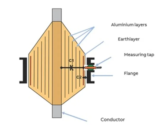
Bushings are composed of a capacitive body (made up of layers of oil-impregnated paper for OIP types and resin-impregnated paper in RIP types), which serves to isolate the central conductor from the grounded points. This is achieved by distributing electrical stresses across the different layers, which can be modeled as capacitances in series.
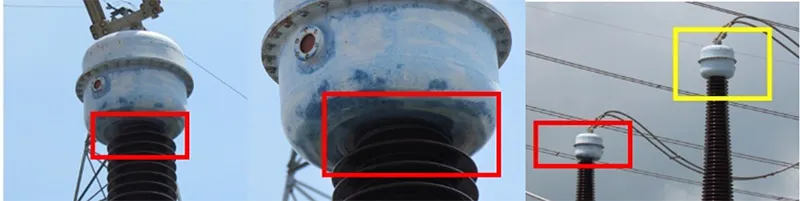
When there are dielectric stresses such as transient overvoltage phenomena, the insulation is stressed causing progressive deterioration. Similarly, when external contamination such as moisture ingress occurs, there is a decrease in the dielectric capacitances of the main insulation. As dielectric characteristics decrease, there are greater losses, which can be detected by periodic power factor tests.
Dielectric failure mechanisms can also include failures in the external insulation of the bushing at the bottom against the ground, decreasing insulation distances in the installation of the equipment or by exceeding insulation levels due to some external event. For example, increased deterioration of 500 kV bushings installed in shunt reactor switching has been observed because the bushings were severely stressed by switching transients. Generally, while bushings are resistant to such events, if repeated frequently, these can result in long-term deterioration of the core insulation.

2. Thermal Failure Mode
One of the periodic maintenance activities on bushings is performance of thermography to detect hot spots at the terminals. These hot spots are due mainly to two causes: insufficient contact with the connector or a galvanic coupling phenomenon.
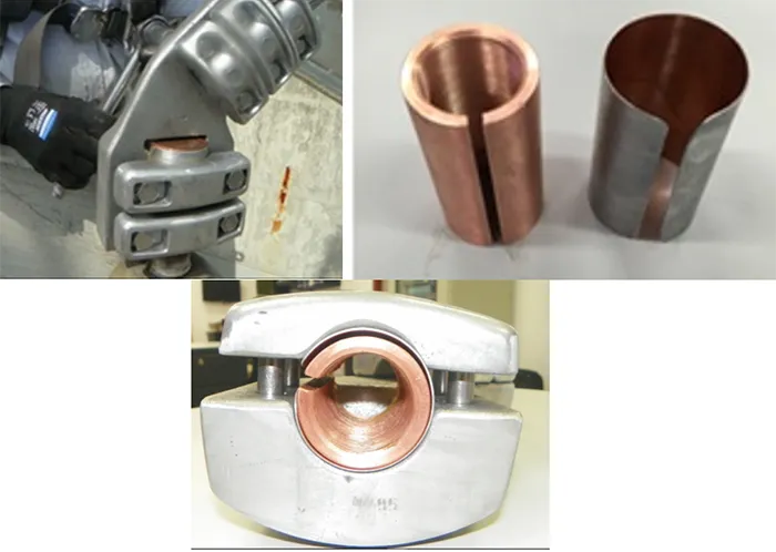
The union of two different metals, such as aluminum and copper, produces an electrochemical effect, whose catalyst is an electrolyte (moisture and impurities). This leads to corrosion of the metal by oxidation-reduction, which in this case is in the aluminum. This oxide is essentially a resistance to flow of current, which translates into a hot spot. Figs. 6 and 7 show such a hot spot and the solution implemented using a bi-metallic plate.
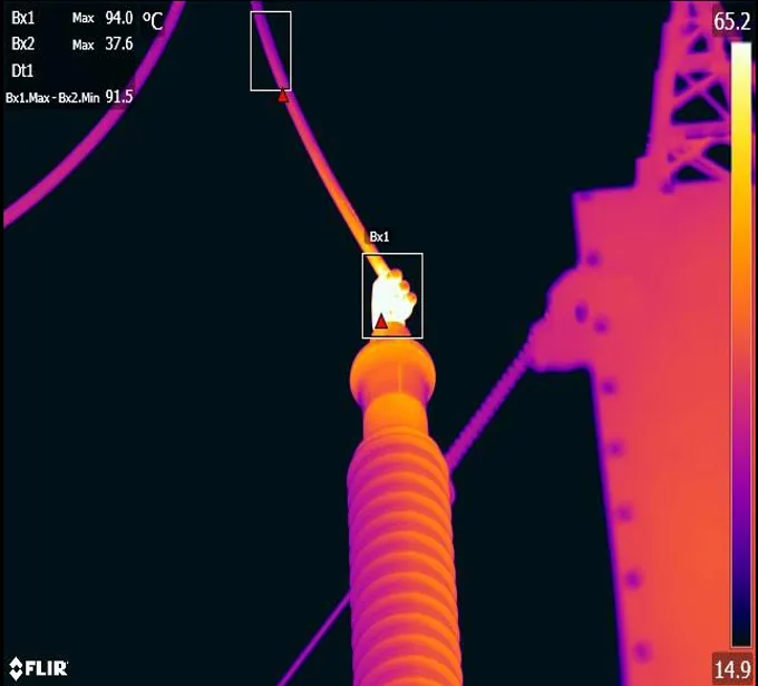
Insufficient contact with the connector is the most common cause of hot spots on bushing terminals. This can be caused by several factors, such as loose connections, corrosion, or damage to the connector. When there is insufficient contact, resistance of the connection increases, which can lead to heat build-up. High temperature over a prolonged period can affect the gasket in the top head of the bushing, increasing risk of moisture ingress.
3. Mechanical Failure Mode
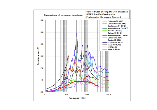
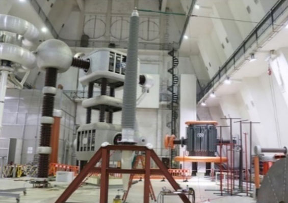
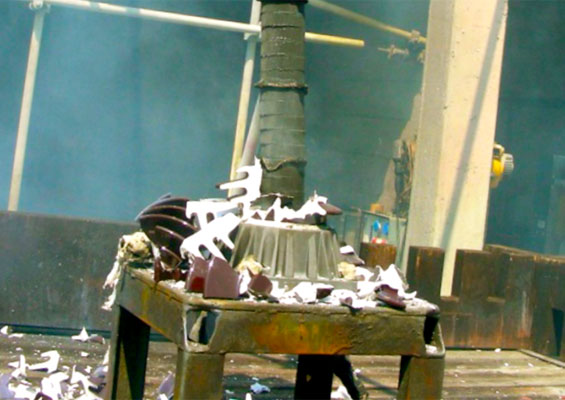
Among the events of greatest stress to which bushings can be subjected in relation to their mechanical component are those caused by seismic activity. Indeed, according to a CIGRE 755 reliability study, 18% of bushing failures are associated with seismic events. This could be explained by the fact that the mechanical resonance frequency of the bushing can be very close to that of the earthquake.
In recent years, efforts have been made to prevent such problems on both RIP and OIP technologies with polymeric insulation that performs better during an earthquake. Similarly, simulations based on vibration tables and calculations according to IEEE 693-2018, allow bushing designs that perform well even under seismic events.
There can also be mechanical stresses from the temples that connect to the bushings. If not left with sufficient clearance, when there are changes in conductor temperature, phenomena of elongation and contraction occur that could affect the upper part of the bushing.
Within the strategies for restoring operation whenever any unit fails, movement of the transformer mounted on rails in the substation is considered. Such movements can affect bushings depending on the accelerations that occur.

4. Chemical Failure Mode
Bushing damage can also occur from the factory. Failures have been reported in OIP bushings caused by oil contaminated with corrosive compounds that can react with the copper of the central conductor and affect insulation under certain temperature conditions. Reaction between these corrosive compounds is triggered at high temperatures, generally above 80°C.
Historical Analysis of Bushings: Date Driven Trends & Insights
Before starting with construction of a methodology for proactive evaluation of the condition of bushings, it was necessary to explore data on the fleet of bushings at ISA INTERCOLOMBIA. Age distribution, manufacturer, and age at time of renewal were all analyzed. Looking at historical data allows interpreting and analyzing patterns that might otherwise remain hidden within the fleet of bushings.
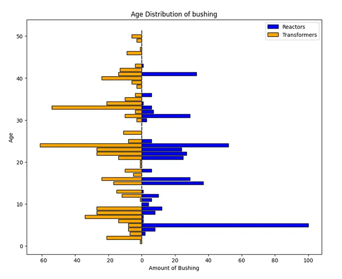
In this case, greater dispersion was identified in bushings aged older than 35 years installed in power transformers. This demanded greater attention since these are the equipment with the greatest history of stress. On the other hand, reactor bushings peak at the age of 41 years with 33 bushings at the 500 kV level. This represented a challenge because bushings installed in switching shunt reactors have been the main element renovated based on condition using the test of capacitance and dissipation factor (DF) measurement. The reason behind this is that switching overvoltage causes progressive deterioration along the life cycle, even though bushings are designed to operate under such critical conditions.
Taking stock of the bushings renovated over the past 10 years, it was observed that the average age of those bushings was 35 years. This result is relatively close to the trend observed in CIGRE 755 (Transformer bushing reliability). This survey presented the distribution of years of service before failure and highlighted that the main concentration of failures occurs between 21 and 30 years in service, with a distribution of 31% of the bushings in the study.

Risk Assessment Methodology
It has been noted that life expectancy of bushings can be a little less than that of the transformer. As such, carrying out proactive renewal will help ensure reliability of transformers and shunt reactors.
Performance and reliability of an asset is influenced by inherent reliability (how it was designed), the operational environment (how it has been operated) and the maintenance plan (how it is been maintained). These aspects were considered in a comprehensive evaluation methodology developed to define and prioritize the renovation of bushings.
This was applied to bushings older than 35 years based on study of historical data. According to behavior of different parameters such as age, historical electrical stresses, design, and evolution of diagnostic tests, bushings were prioritized by assigning them a risk level on a scale of A (high), B (Medium) and C (Low). Fig. 10 summarizes this evaluation methodology.
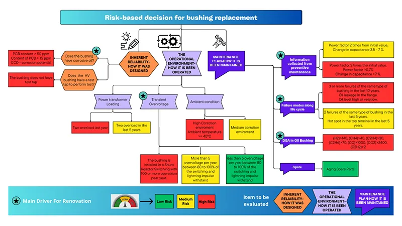
The main driver for a replacement decision are results from the maintenance plan, for example historical behavior during electrical testing, number of bushing failures of the same type and results of dissolved gas analysis. Normally, the last test is performed whenever a wear electrical test result is obtained.
From the perspective of operational environment, it is considered that a main driver is transient overvoltage. Finally, from the perspective of inherent reliability, a key consideration is contamination of a bushing’s insulating oil with corrosive components.
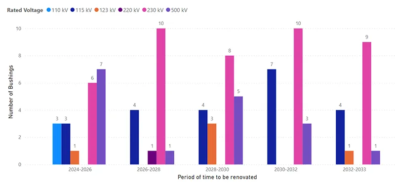
This evaluation methodology was applied to bushings older than 35 years, according to what had been identified from exploration of historical data. According to behavior of these various parameters, bushings were prioritized by assigning them a risk level on a scale of A (high), B (medium) and C (low). This allowed structuring a renovation plan projected until 2033.
In total, there would be 91 bushings – a very large task that could not reasonably be completed in a single year. Prioritization made it possible to structure a medium-term plan, as is shown in Fig. 11.
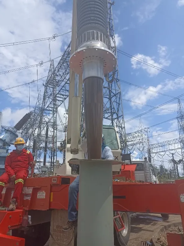
The decision to renew bushings must be correlated with the remaining life of the active part of the transformer and reactor. Otherwise, the investment to renovate the bushings would only be useful for a few years. These are bushings that have been in service for more than 35 years and their original manufacturers may no longer offer these same types. Therefore, there would be a need to purchase custom-made units.
To meet this challenge, a supply agreement was structured with 3 bushing suppliers, allowing for price competition as well as managing supply risk by not depending only on a single supplier. As part of this plan, ISA INTERCOLOMBIA is changing bushing technology from OIP to RIP.
Circular Economy Through Proactive Renovation of Bushings
Replacing bushings proactively helps extend the life expectancy of a transformer and can also help utilities reduce their carbon emissions given that many tons of CO2 are generated during manufacture of a new transformer. Although the cost of this main component represents a fraction of the total cost of a transformer, a bushing renovation plan contributes to the circular economy.
There are different frameworks and initiatives for the circular economy in the power industry, but the underlying fundamentals of each are similar. These include reducing natural resource use, extending product/equipment life, and eliminating resource loss. In particular, the useful service life of a transformer is extended when proactively renewing those bushings with highest risk of failure. This is especially the case given that failures can have high collateral impact such as fire in the power transformer or shunt reactor.
Conclusions
In the face of increasing global demand for reliable power, ensuring the longevity and optimal performance of energy infrastructure becomes paramount as part of the energy transition and the requirement for a circular economy. As discussed, bushings play a crucial role in transformer reliability and lifespan. It has also been shown that life expectancy of bushings can be less than that of the transformer. Therefore, carrying out proactive bushing renewal will help guarantee reliability of transformers and reactors.
Regular bushing maintenance is crucial but can still fall short of addressing life extension needs. Given this, a comprehensive evaluation methodology has been developed in Colombia that addresses factors beyond age alone, including operating environment, historical stresses, and findings from diagnostic tests.
This methodology enables risk-based prioritization of bushing renewal. By assigning risk levels (A-high, B-medium, C-low) to bushings with more than 35 years’ service, a well-defined and manageable renewal plan has been structured until 2033. This prioritization strategically applies to the large number of bushings (91 in the case of ISA INTERCOLOMBIA), ensuring optimal resource allocation and minimizing operational disruptions.
This article advocates a paradigm shift in life extension strategies for power transformers. By prioritizing and integrating a comprehensive evaluation and renewal plan for bushings, continued reliability and resilience of vital energy infrastructure can be ensured in the face of growing demand and evolving challenges.
Bibliography
[1] Güner, D. Gosselin. “Need for circular economy, Refurbishment of large power transformers”. Transformer Magazine. Special Edition: Sustainability. 2023
[2] CIGRE Technical Brochure 887: Life extension of oil filled transformers and shunt reactors, WG A2.55, December 2022.[2] CIGRE Technical Brochure 887: Life extension of oil filled transformers and shunt reactors, WG A2.55, December 2022.
[3] Gulati, R. (2020). Maintenance and Reliability Best Practices Third Edition. Industrial Press, Inc.
[4] INMR, “Increasing Transformer Reliability by Proactive Bushing Fleet Management” 2023. [Online]. Available: https://www.inmr.com/increasing-transformer-reliability-by-proactive-bushing-management/. [Accessed 21 05 2023]
[5] CIGRE Technical Brochure 755: Bushing Reliability Survey, WG A2.43, 2019
[6] Mark D. Tostrud. Failure Characteristics of OIP VS. RIP Bushings. 2017 Doble Engineering Company – 84th International Conference of Doble Clients.
[7] “IEEE Standard for General Requirements and Test Procedure for Power Apparatus Bushings,” in IEEE Std C57.19.00-2023, pp.1-32, 15 May 2023.
[8] E. L. Cantor Huerfano and F. A. Herreño, “Asset Lifecycle Management Analysis to Select Bushing Technology with the Optimal Combinations of Costs, Risks and Performance,” 2019 FISE-IEEE/CIGRE Conference – Living the energy Transition (FISE/CIGRE), Medellin, Colombia, 2019, pp. 1-4.
[9] EPRI. A Framework for the Application of Global Circular Economy Principles for the Electric Power Industry.2021.