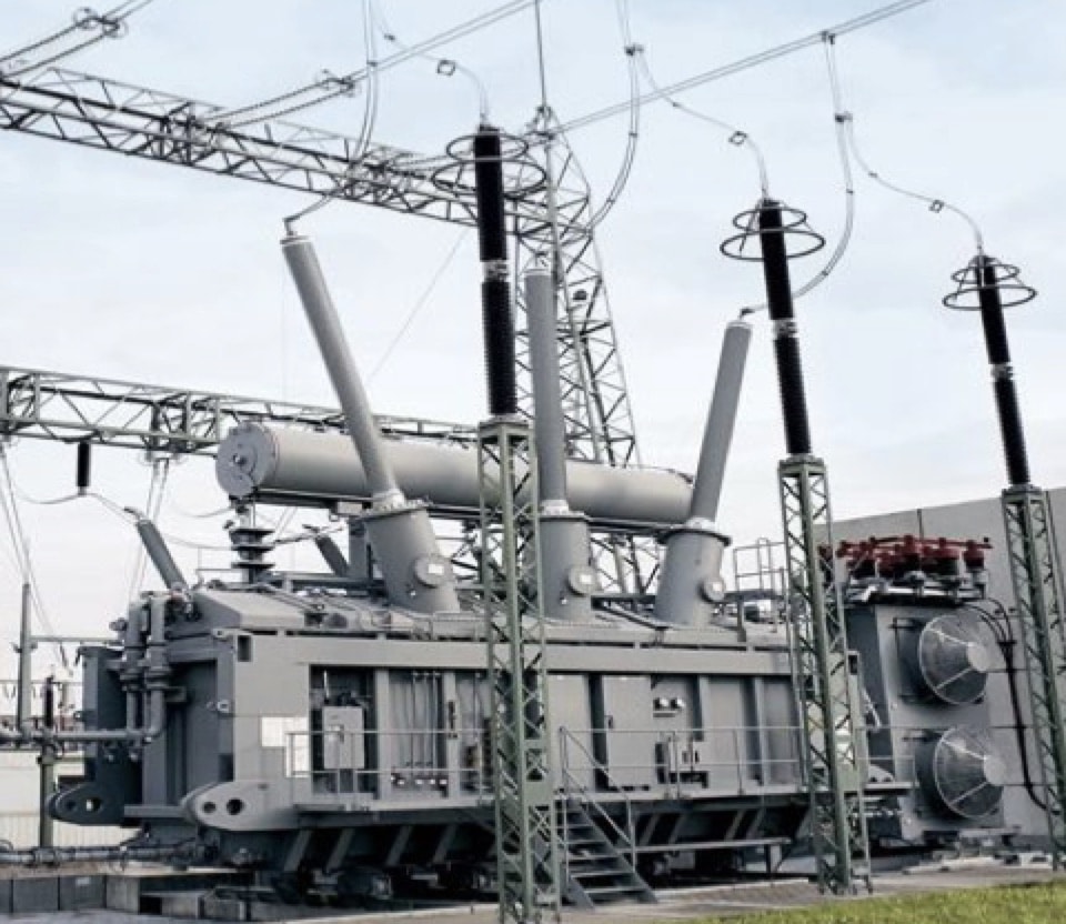
Bushings are insulating structures used at all voltage levels for a variety of applications, including in transformers, shunt reactors, gas-insulated switchgear, circuit breakers, HVDC halls and generators. In the case of transformers, although bushings are long-proven devices, investigation of transformer failures still points to them and their in-service operating conditions as causing a significant share of unplanned outages and transformer failures. As a result, new bushing technologies, materials and remote bushing online sensors have been developed to address these issues.
This edited past contribution to INMR focused on air-to-oil bushings using resin-impregnated synthetic (RIS) as the main insulation and applied in power transformer and shunt reactors in systems up to 550 kV.
Bushing Technologies
Bushings for transformers and other applications evolved considerably over the decades, from simple hollow insulators made of porcelain to more elaborate, engineered designs. As bushing voltage levels increased, technologies such as capacitance grading and resin-bonded paper (RBP) bushings were developed.
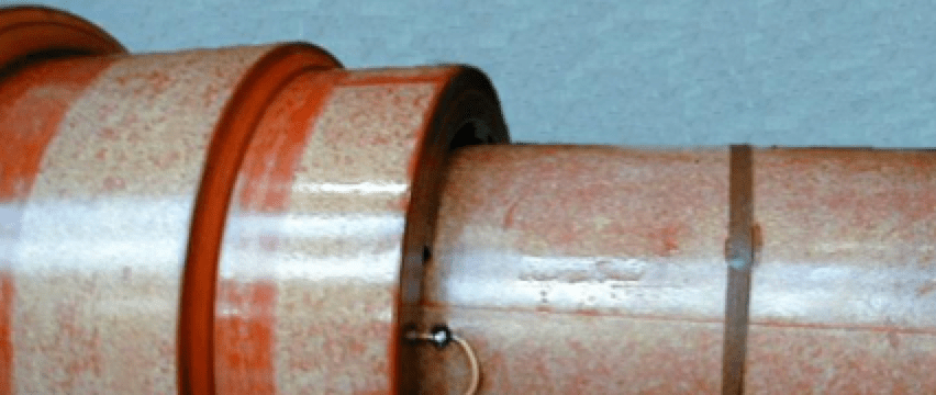
 Later, when RBP bushings reached their limits in terms of partial discharge and dielectric loss, other insulation technologies emerged. Oil-impregnated paper (OIP) technology, although mature and still the most widespread in terms of application, comes with serious risks inherent to use of mineral oil as the insulating fluid:
• Possible loss of insulation media due to ageing of gasket;
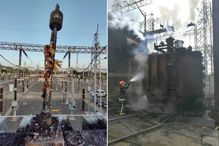
• Potential catastrophic failure and fire when operated under abnormal conditions;
• Flammability of oil.
Moreover, under unusual conditions and in the presence of heat as well as the by-products of cellulose degradation, there is risk of physical and chemical reactions between mineral oil and other materials inside the bushing. These have been known to cause corrosive sulfur and copper mobility problems.
Another potential issue inherent to use of OIP bushings is onset of internal partial discharges due to formation of gas bubbles within the oil. Whenever oil and a gas, whether air or nitrogen, is confined in a fixed volume, as the case for a bushing, pressure equilibrium is reached over time at any given temperature. But when temperature changes so too do volume of oil and also gas space. Three variables then come into play. Firstly, gas pressure changes with volume. Second, gas pressure changes with temperature and third, the ability of the oil to absorb gas varies with temperature. As a result, major fluctuations in temperature result in a continuous change in the amount of gas dissolved in the oil. For example, if temperature drops rapidly after being high for some time, the gas cannot escape quickly enough to avoid formation of bubbles in the oil. This phenomenon occurs mostly during transformer testing in the factory but can also take place when the equipment operates under severe cyclic loading combined with rapid cooling, such as in solar and wind generation.
Dry-type resin-impregnated paper (RIP) bushings have been successfully applied worldwide for many years and effectively eliminate issues related to oil reactions, leaks and flammability. This lowers risk of bushing failures that result in explosions or transformer fires, particularly when used in conjunction with composite housings in place of porcelain. Indeed, as RIP technology has become more and more widespread and with demonstrated reliability, utilities in areas that used to be entirely focused on OIP technology, such as the U.S. and IEEE markets, are increasingly adopting dry bushings as the preferred solution. This is especially the case for high and extra high voltage classes ranging from 230 kV and above. However, RIP bushings still present a shortcoming, namely the potential for moisture ingress in the exposed oil side during long-term storage. That risk requires specific storage methods, including use of oil- or gas-filled tanks to protect an RIP bushing’s lower section.
More recently, the crepe paper used in winding the RIP core has been replaced by a polyester synthetic material. This has resulted in development of what has become known as the resin-impregnated synthetic or RIS type bushing. These are based on the same established condenser grading technology and manufacturing processes as RIP but use of a non-hygroscopic synthetic material eliminates risk of moisture ingress. At the same time, other bushing insulation characteristics improve as well.

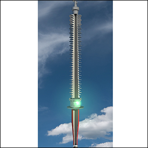
RIS Bushing Construction
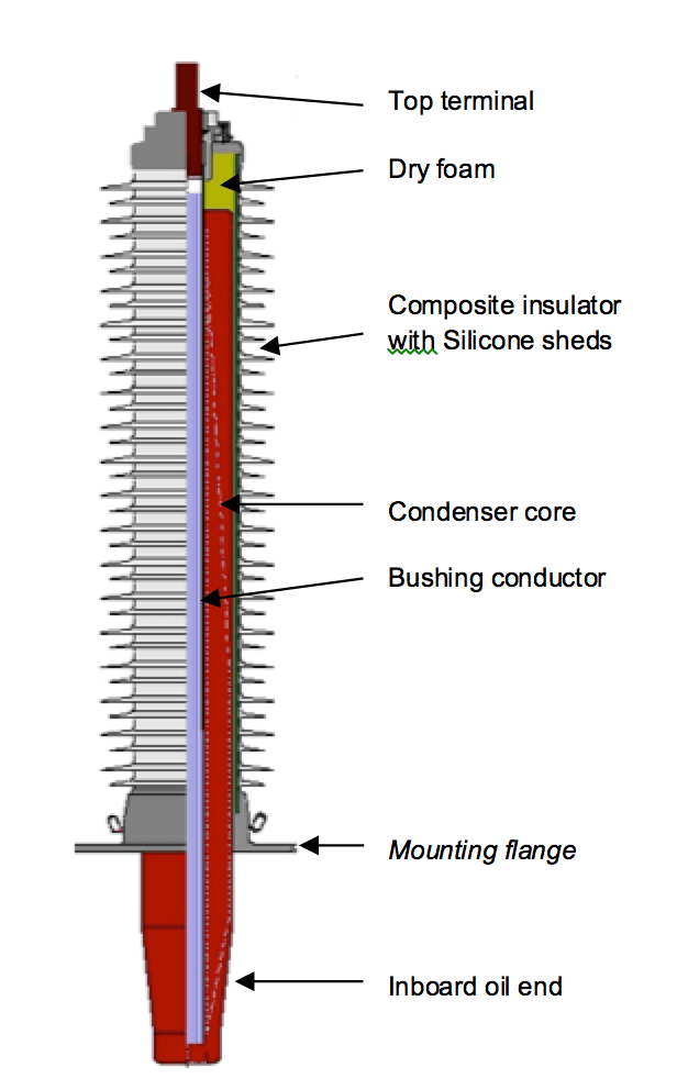
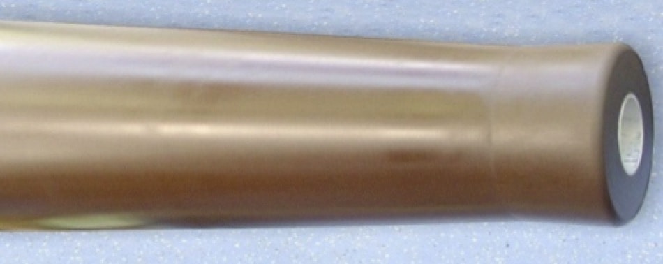
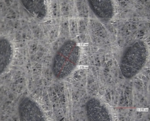
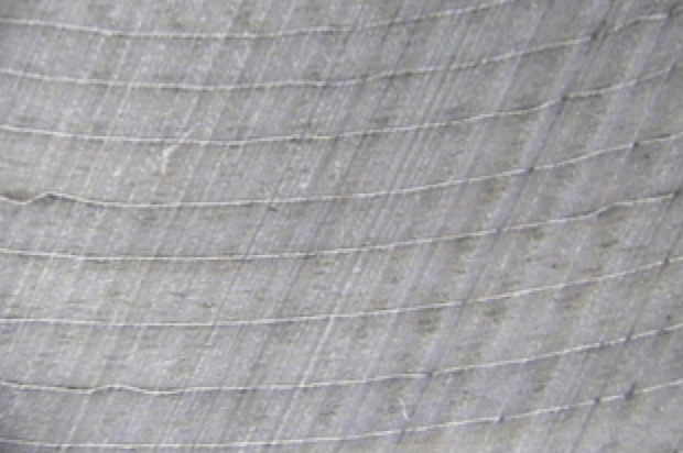
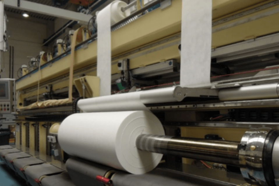
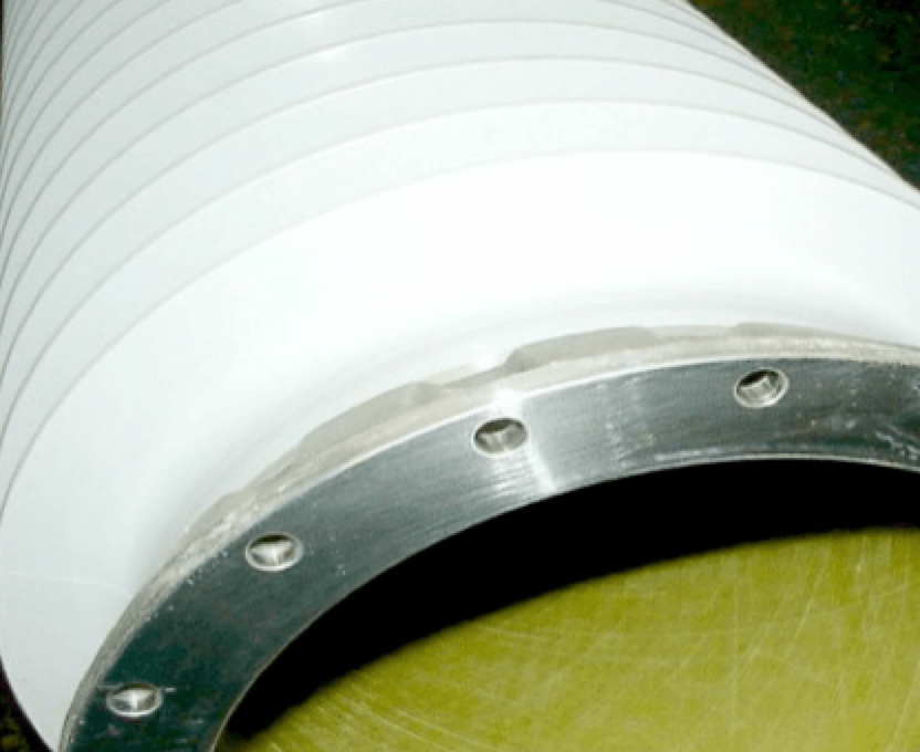
The construction of an RIS type bushing is similar to other technologies with available drawlead or bottom connection options. The active part, or condenser core, consists of a thin non-woven synthetic fabric wound tightly around an aluminum tube or solid copper rod. During winding, condenser electrodes made of thin aluminum foil are introduced at specific locations and intervals to provide electric field grading in the bushing’s radial and axial directions. The synthetic fabric, manufactured to specific tolerances, has homogeneous properties, consistent thickness and smooth surface finish that together allow smooth insertion of aluminum foil during the winding process. The result is superior placing of concentric layers and more uniform electric field distribution.
Synthetic Insulation Properties
The synthetic insulating material used in RIS bushing condenser cores is non-hygroscopic. This ensures that virtually no ambient moisture is absorbed either during raw material storage in the factory or later within the finished bushing condenser core.
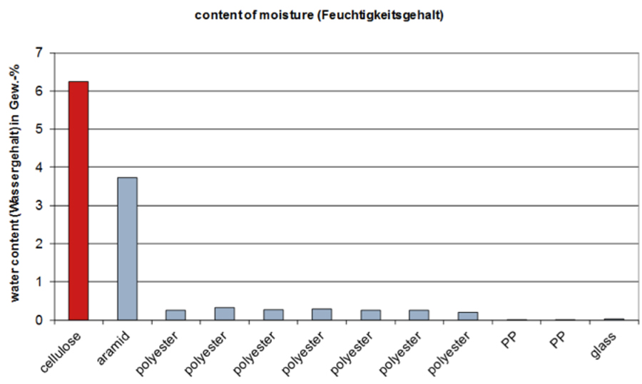
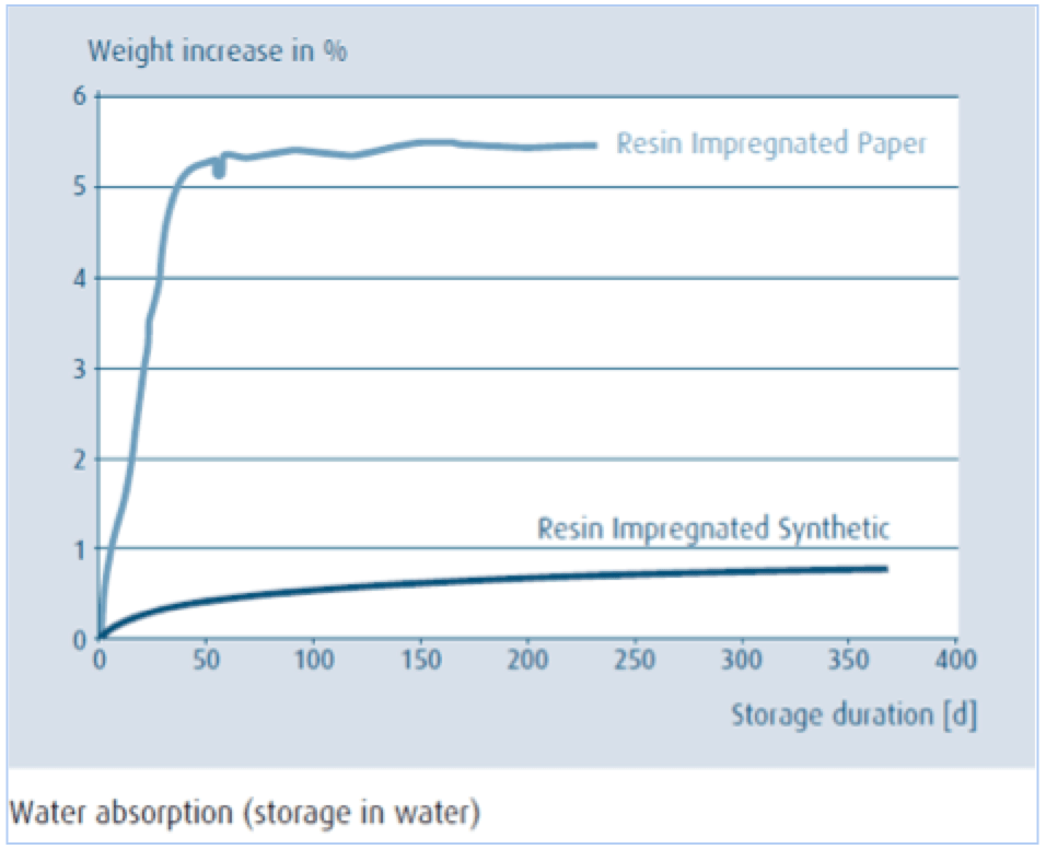
Fig. 2 compares moisture content, in percentage of weight, after prolonged storage at 50% relative humidity and 23ºC for a range of different insulating materials. As can be seen, cellulose gains 6.24% in weight due to moisture absorption whereas synthetic materials remain at only 0.23% to 0.32% weight gain. In fact, samples of resin-impregnated insulation stored under water for a long-term yielded similar low water absorption, as shown in Fig. 3.
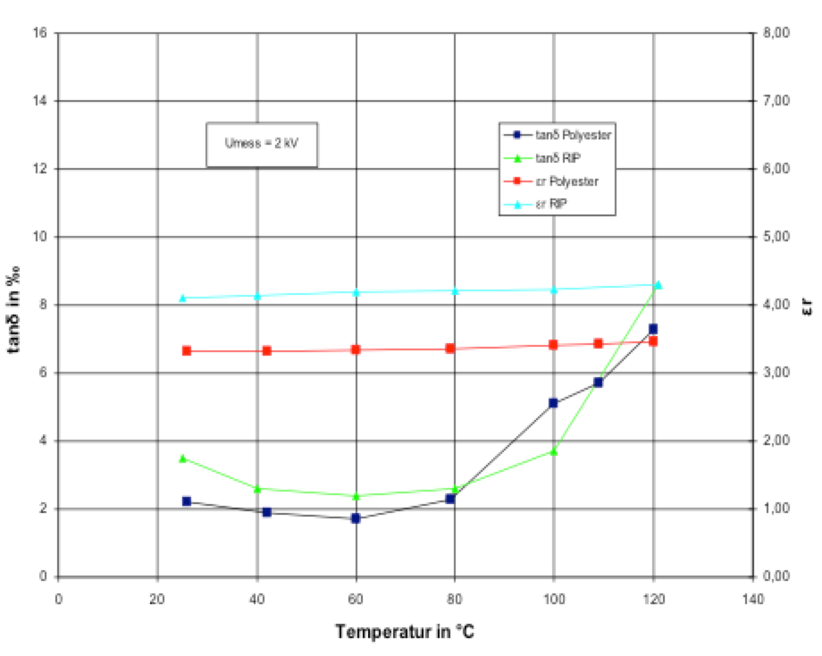
At the same time, from a dielectric point of view, resin-impregnated synthetic material has stable properties that are comparable in permittivity and power factor to the crepe paper used in RIP bushings. The curves in Fig. 4 show power factor and relative permittivity for these materials as a function of temperature. This similarity in dielectric properties allows for easy interchangeability of RIP/RIS bushing designs in terms of dimensions as well as electrical ratings.

RIS Bushings
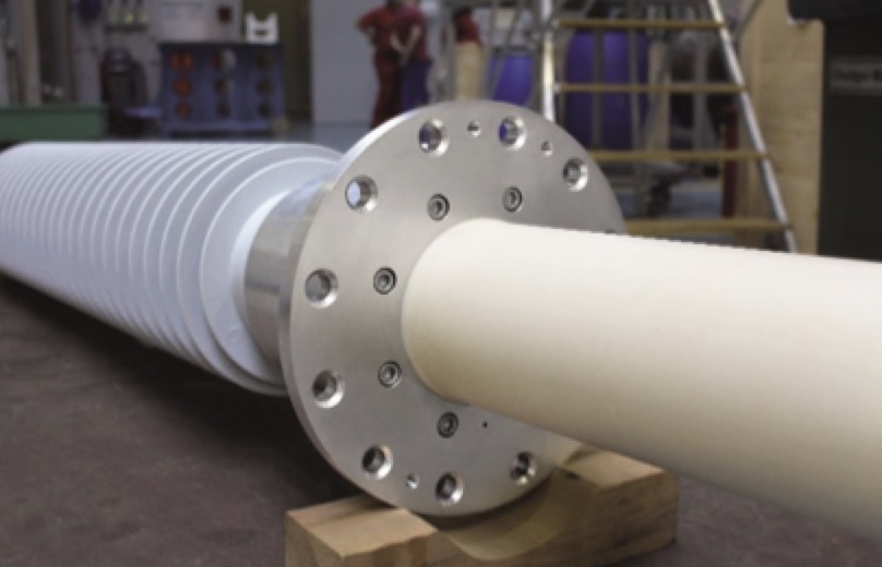
Since introduction, RIS style bushings have been installed and placed in service around the world. For example, some types of RIS bushings were introduced into the IEEE market in 2016, mainly at 230 kV, 345 kV and 550 kV system voltages. Annex 1 shows the typical technical specification for a 550 kV 3000-amp RIS replacement bushing according to IEEE C57.19.01 ratings. The distinctive slender construction of these bushings and use of standard components such as insulators, flanges, etc. allows easy customization of an RIS transformer bushing to dimensionally match whatever legacy bushings are being replaced.
The main advantages of RIS bushings, equipped with composite insulator housings, include:
• Construction free of oil and paper;
• Flame-resistant properties;
• Insulation thermal class of 120ºC;
• Lower sensitivity to humidity ingress during long-term storage;
• More controlled winding and also better electric field profiles;
• No dangerous fragments if housing damaged by internal or external factors;
• Low risk of damage due to improper handling and vandalism due to high impact strength and shock resistance;
• Lower weight, simplifying handling and reducing stress on transformer tank;
• Suitability for even very low ambient temperatures;
• Seals designed as O-rings in self-contained channels and made of temperature-resistant elastomers;
• Voltage tap and/or test tap according to IEEE requirements;
• Easier transport and storage in any position;
• Availability per IEEE voltage classes and current ratings up to 550 kV;
• Complying and exceeding applicable IEEE bushing standards and tested accordingly.
Routine Testing
According to IEEE C57.19.00, routine tests are intended to verify quality and uniformity of workmanship and materials used in manufacturing transformer bushings. Every unit manufactured to this standard must undergo a full such test as part of the production process. Since condenser bushings made of synthetic materials are yet to be covered by any IEEE standards, acceptance criteria for some routine tests are still not defined. Manufacturers are therefore required to demonstrate ratings by what they consider equivalent or more adequate test limits. Suitable limits for power factor and partial discharge testing in the case of RIS bushings are discussed below:
Bushing Power Factor
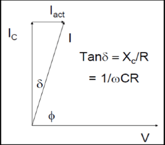
Power factor is the measure of internal dielectric losses within the bushing insulation, relative to its capacitive reactive power, expressed in percentage. Fig. 5 shows the phasor representation of the resistive and total currents flowing through the condenser core, with Cos Ø being the ‘power factor’ of the insulation. In an ideal capacitor, the active current, Iact, would be near zero (i.e. no losses) and the ideal power factor would also approach zero as the phase angle, Ø, nears 90º. In practical terms, a power factor of 0.005 (0.5%) or lower is considered healthy.
As for bushings using other insulation technologies, RIS bushings are factory tested for C1 main insulation capacitance and power factor at 10 kV at normalized ambient temperature of 20ºC. These values are stamped in the nameplate for reference and condition assessment of the bushing in the field. Typical C1 power factor values for a new RIS bushing range in the order of 0.25% to 0.4%, depending on bushing voltage class. Field-testing RIS bushings at temperatures other than the normalized 20ºC requires application of correction factors, available in the instruction manual or from the manufacturer, as shown in Fig. 6. Deviations in C1 capacitance or power factor are indications of possible ageing or damage within the insulation and therefore must be investigated.
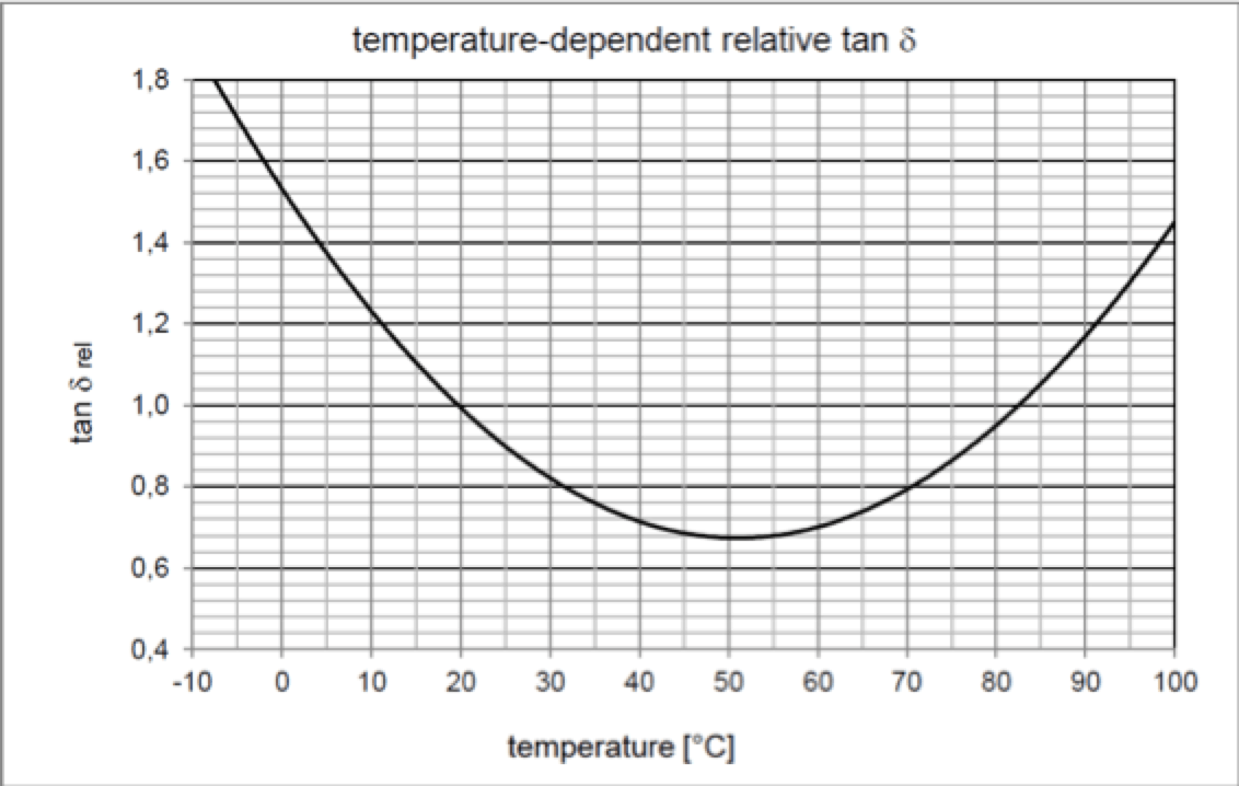
Correction factor, K, is the reciprocal of the relative Cos Ørel: from the correction curve in Fig. 6: K = 1/Cos Ørel. For example, C1 field-testing of an RIS bushing, with nameplate power factor of 0.26%, at cold ambient temperature yielded:
Mean temperature of bushing based on ambient and transformer oil temperature:
Tbushing = 10°C
Measured C1 Cos Ø from insulation analyzer:
Cos Ø @10°C = 0.32%
Relative Cos Ø for 10ºC, from curve:
Cos Ørel = 1.2
Correction factor: K = 1/Cos Ørel = 0.83
Corrected C1 power factor to normalized ambient of 20ºC: Cos Ø = K * 0.32 = 0.26%, matching nameplate value.

Partial Discharge (PD)
Partial discharges occur whenever there is discontinuity in electric field intensity that exceeds the dielectric withstand of a small portion of an insulating material. It is therefore critical that factory acceptance testing detects any PD anomaly for inception and extinction at the prescribed voltage level. Dry type RBP bushings have intrinsically higher partial discharge levels since tiny voids and cracks are normally formed during manufacture of their condenser cores. In fact, PD-related damage is a common cause of failure for this type of bushing since self-healing of the insulation, as the case for air or OIP insulation, is not possible.
By contrast, modern resin-impregnated RIS dry-type condenser cores for transformer bushings undergo more stringent impregnation and drying. This process is carried out under vacuum and strictly controlled temperature and duration, ensuring no formation of voids or cracks. The result is bushings with no detectable PD up to the highest system voltages. Validation of the manufacturing process is done during routine testing of the complete bushing. Here, PD is measured at increasing AC test voltage steps up to the one-minute power frequency withstand test level, UP, while simultaneously also measuring main insulation C1 capacitance and power factor. Only external test laboratory background PD should be detected and 1 pC internal PD is set as acceptance criteria during the bushing test at 10 kV; 0.5VL-G; 1.05VL-G; 1.5VL-G; 1.82VL-G; 2.0VL-G; UP and decreasing back to 10 kV through the same voltage steps. This special factory test confirms that PD inception voltages for RIS bushings are never reached, even at the highest possible bushing operating voltages or temporary system overvoltages. It also verifies that there are no deviations in C1 capacitance and power factor values at various test voltages.
Impulse Testing
According to IEEE C57.19.00-2004, Section 7, any impulse testing of transformer bushings is considered a design test and not a routine test. This means that impulse tests are not required during factory acceptance tests. For end-users, it is considered best practice to include impulse tests in the transformer bushing technical specifications they issue in order to ensure that the manufacturer selected has implemented some form of impulse testing during the routine test plan. For example, the impulse test sequence included in IEC 60137-2017, Section 9.3 should be requested for all bushings rated above 69 kV voltage class. The impulse test sequence should include, as a minimum:
• one full lightning impulse of negative polarity at 105 % of rated withstand voltage followed by;
• two chopped lightning impulses of negative polarity at 115 % of rated withstand voltage, followed by;
• four full lightning impulses of negative polarity applied at 105 % of rated withstand voltage.
Full AC routine tests should be performed before and then repeated after the impulse test sequence. This practice is particularly important for replacement bushings, where these would not be subjected to any impulse tests during the transformer factory test.

Bushing Replacement
During routine maintenance and inspection of power transformers, several critical aspects are checked in regard to the bushings. Condition of the bushings is assessed based on results of this inspection or through an on-line bushing sensor. Main reasons why a bushing needs to be replaced include:
• Increase in power factor, capacitance or PD above manufacturer recommended values;
• Loss of oil or identified oil leak;
• Presence of combustible gasses in the bushing oil;
• Damaged bushing.
Other factors to consider in determining whether or not to replace a bushing are:
• Inadequate bushing specification or technology for the application;
• Older style bushing that do not allow for installation of remote monitoring.
Further special issues to consider include:
• Outdated/changed technical specification or obsolete standards;
• Unusual operating conditions and renewable energy/special applications;
• Demanding load profiles under abrupt changes in operating and ambient temperatures;
• Bushing air-side termination with rigid bus connection.
Selecting Replacement Bushings
Thousands of transformer bushings are replaced every year. RIS bushings are compatible for replacing legacy bushings from most manufacturers and their manufacturing process allows for customization of dimensions as well as for special designs. When replacing bushings connected via draw lead cables, RIS bushings can be provided with customized adapter bolts or studs to match existing draw lead studs with no or only minimal changes to the draw lead cable. When replacing bushings in high seismic zones or near coastal region where pollution and salinity are severe, bushings equipped with composite insulators and hydrophobic silicone sheds should be used. These insulators are ideal for such service locations since they are mechanically stronger than porcelain and also provide better performance under heavy pollution.

Key Parameters to Consider
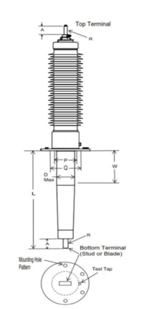
Fig. 7 provides critical dimensions, as per IEEE C57.19.01-2017 Section 4.
• Suitable bushing technology;
• Current rating equal or greater than existing bushing;
• Turret, tank cover and CT opening allowance;
• Static shielding requirements and tank clearances;
• Lower length “L” dimension;
• Lower end diameter ‘Dmax’;
• Bottom connection configuration A, R;
• Flange mounting BCD and number of holes;
• Air side height and air clearance requirements;
• Mounting angle to vertical;
• Top terminal configuration, A, R.
Meeting the above critical dimensions as well as verifying internal transformer tank electrical clearances and shielding provisions will help minimize risk of bushing incompatibility.
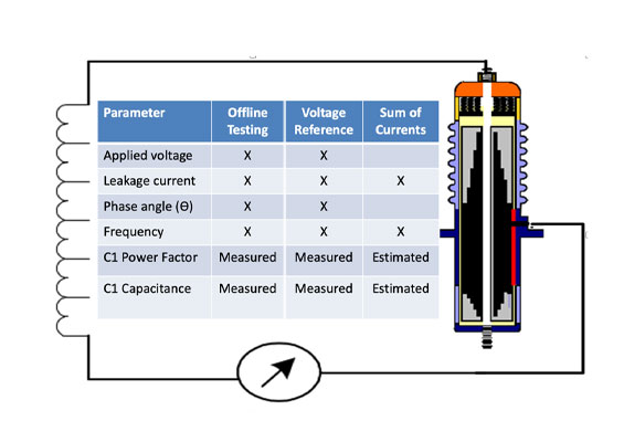
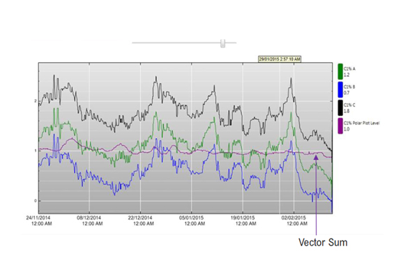
In addition to improvements in bushing technology, on-line sensors also contribute to prevention of transformer failures. For example, Siemens has an upcoming sensor system measuring capacitive leakage current and providing comparison/sum of values to provide basic information on health of a bushing. Benefits include reducing unplanned outages as well as cost savings achieved through planning replacement or mitigation measures.
Conclusions
Resin-impregnated synthetic style bushings represent an exciting technological innovation and these oil-free, paper-free dry transformer bushings are now available for system voltages up to 550 kV. The flame-resistant insulating body of each RIS condenser bushing is made of a special synthetic impregnated with epoxy resin under vacuum. The design of these new bushings is based on mature RIP condenser core technology, proven in field for more than 60 years. While paper is a good electrical insulation material, it is also hygroscopic and absorbs moisture from its environment. Humidity negatively impacts power factor and ageing of bushings but proper drying of paper is time and labor-intensive process during manufacture. Following an intensive development program, the special paper used in RIP bushings can now be replaced with a synthetic web with more homogeneous properties and minimal moisture absorption that substantially reduces or even eliminates such disadvantages.
RIS bushings are characterized by stable dielectric properties, attributable in part to the major reduction in risk of moisture absorption at exposed active surfaces, e.g. the oil end of transformer bushings. In addition, their higher temperature class gives bushings of this series greater thermal reserves. Since RIS bushings are not oil-filled, there are no constraints with regards to the storage position. The standard RIS bushing are designed for installation in a position 0-30° from the vertical and in many cases horizontal installations at 90º from vertical are possible.
References
[1] C57.19.00-2004 IEEE Standard General Requirements and Test Procedures for Power Apparatus Bushings
[2] CIGRE Transformer Reliability Survey WG A2.37 Interim Report April 2012
[3] CIGRE Transformer bushing reliability A2-755 2019
[4] Bushings for power transformers, K. Ellis. AuthorHouse, 2011.
[5] Section 4.1.2, CIGRE Transformer bushing reliability A2-755 2019
[6] Bubble evolutions in bushings, ABB publication 1ZBC000001C2704, 2011.
[7] Parts and Service News For the Power Transformer and Circuit Breaker Maintenance Community, March 1998, Special No. 1
[8] C57.19.01-2017: IEEE Standard for performance characteristics and dimensions for power transformer and reactor bushings
[9] IEC 60137-2017: Insulated bushings for alternating voltages above 1000V