The global expansion of high voltage power grids is driving a significant increase in the deployment of new transmission and distribution (T&D) components, including high and ultra-high voltage cables. To ensure proper cable installation and the correct assembly of accessories, international IEC standards mandate electrical testing after installation—known as commissioning tests—for newly installed cable circuits.
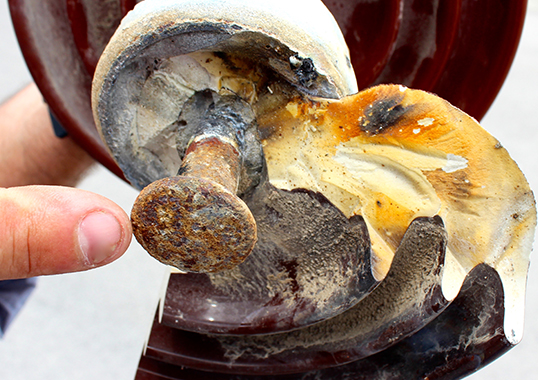
These tests are typically conducted using specialized mobile test installations mounted on trucks, capable of energizing cables to the required test voltage. In conjunction with this, partial discharge measurements are performed to detect potential insulation defects. The occurrence of electrical breakdowns during commissioning tests highlights the critical importance of these procedures in identifying latent installation issues before cables are put into service.
This edited contribution to INMR by Bas Verhoeven and Klaus Vaterrodt of KEMA Labs reviews a statistical analysis conducted using an internal database that contains records from hundreds of commissioning tests. Results reveal insightful trends when examining the number of tests performed annually, categorized by voltage class and circuit length. These findings contribute to a deeper understanding of the reliability and performance of HV cable systems under real-world conditions and reinforce the necessity of commissioning testing.
Methods for Commissioning Testing
The use of cross-linked polyethylene (XLPE) insulated cables for high-voltage connections began in the late 1980s. Unlike traditional paper-oil insulated cables, XLPE cables are not suitable for DC commissioning tests due to the risk of space charge accumulation. This phenomenon can lead to insulation degradation and long-term reliability issues, making DC testing methods unsuitable for modern XLPE cable systems. Alternative Test Methods for commission tests:
• VLF (Very Low Frequency) Testing
Conducted at 0.1 Hz, this method combines the benefits of AC voltage testing with the simplicity of DC technology. However, the non-sinusoidal periodic polarity reversals can initiate electrical treeing, potentially leading to insulation breakdown. Consequently, VLF is only used for medium voltage cables.
• DAC (Damped AC Voltage Testing):
While DAC also induces treeing phenomena, the primary concern lies in the monopolar voltage pre-stress it imposes on XLPE cable systems. As a result, many experts consider DAC more suitable for diagnostic assessments like partial discharge measurement rather than commissioning tests.
• Resonant AC Testing
Performed at frequencies between 20 and 300 Hz, this method avoids the drawbacks associated with VLF and DAC. Although the equipment is typically large and heavy, recent advancements in modular design have significantly improved its portability and practicality.

Concept of Resonant Test System
The concept of Resonant Test Systems was pioneered by Prof. Zaengl at ETH Zurich, Switzerland. The proof of principle was demonstrated around 1980 using short 150 kV cable sections. Commercial testing of longer high and ultra high-voltage cable connections began in the late 1990s. A notable milestone was the first 400 kV cable test conducted in 1998 for BEWAG (former TSO in Berlin) carried out by IPH and KEMA.
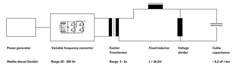
The cable’s inherent capacitance, together with a large external fixed inductor, constitutes a series-resonant circuit, as illustrated in Fig. 1. At the resonant frequency, the voltage across the cable increases substantially, governed by the circuit’s quality factor (Q-factor). Provided that resistive losses in the inductor, exciter transformer and the internal impedance of the variable-frequency power converter are minimal, the Q-factor typically lies within the range of 100 to 200.
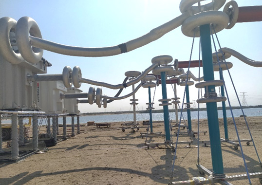
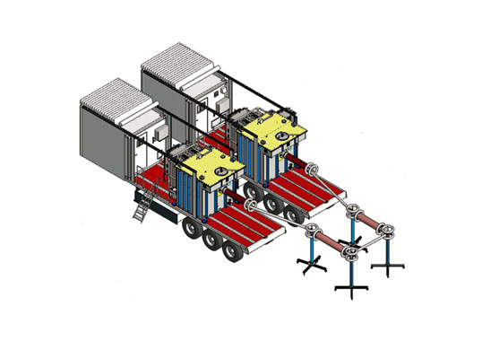
A low-voltage power electronic converter, capable of operating at variable frequencies between 20 Hz and 300 Hz, is tuned to the resonant frequency and supplies the series-resonant circuit via an exciter transformer with a voltage transformation ratio between 1:2 and 1:5. This resonant series excitation (RSE) system is designed to energize cables up to 250 kV with a maximum current of 80 A. The complete system is mounted on a 40-ton truck, enabling transport via standard road infrastructure. For testing extended cable lengths, multiple RSE units can be connected in parallel. To achieve higher test voltages, systems may be cascaded or configured in hybrid arrangements combining both parallel and cascade topologies.
Requirements in IEC standard
The standards IEC 60840 and IEC 62067 are applicable to extruded high-voltage cable systems. Both include provisions for electrical testing after installation (commissioning testing). The primary objective of these tests is to verify the integrity of the cable system including all accessories, by energizing the cable at 1,4 to 1,7 × U0 for a duration of one hour. The cable system is deemed suitable for service if no electrical breakdown occurs during this test.
The standards recommend the use of a sinusoidal waveform with a frequency in the range of 20 to 300 Hz. For very long cable systems, the test frequency may be reduced to 10 Hz. Alternative methods such as very low frequency (VLF) or damped AC (DAC) are not recommended for commissioning tests.
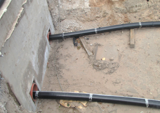
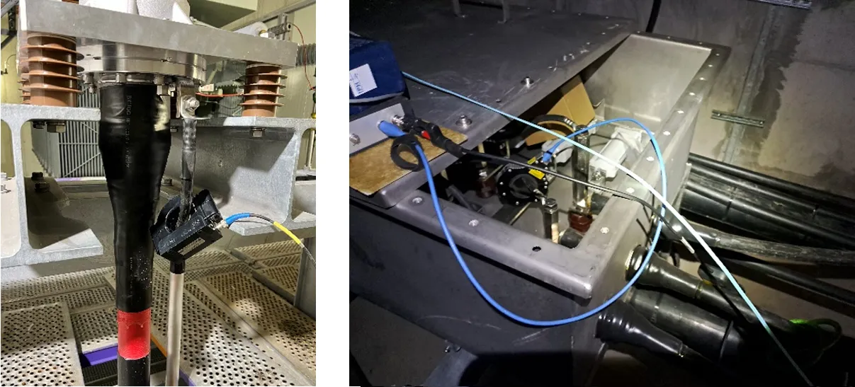
Partial discharge (PD) measurements are advised during the AC voltage test; however, PD testing is not considered a substitute for the voltage withstand test. PD sensors are typically installed on the grounding leads of the terminations at both ends of the cable, as illustrated in Fig. 2a. Due to signal attenuation within the cable, PD signals become undetectable after approximately 2 to 3 km. Consequently, for longer cable systems, distributed PD sensors must be installed at each cross-bonding joint to ensure effective monitoring as shown in Fig. 2b.

On-Site Test: Database
KEMA Labs has been conducting commission tests for customers, primarily across Europe, for over 25 years. The general data from these tests is systematically archived in a dedicated database. The data collected in the database contains records of on-site tests performed by KEMA Labs at its Arnhem (NL) laboratory. The key characteristics of this database are summarized below:
Period: 2010 to 2024 (data in 2021 is missing due to IT issue that year.)
Number of circuits tested: 839
Electrical breakdowns: 75
Voltage class: 66 kV to 420 kV
Total length of circuits: 2,400 km
PD test performed: 78%
Individual circuits length: 20 m to 56 km
In the context of this review, a cable circuit is defined as comprising all three phases. Therefore, the total length of cable tested amounts to 3 × 2n400 km = 7,200 km. The total cable length tested by KEMA Labs is approximately 20,000 km.
Over the years, the number of cable circuits tested annually has remained relatively stable, averaging approximately 60 circuits per year. The individual circuit lengths exhibit substantial variability, ranging from as short as 20 meters to as long as 56 kilometers. Furthermore, the tested cable circuits span a range of system voltages from 66 kV to 420 kV, contributing to a diverse dataset. To analyze the database, the following three research questions were formulated:
1 Reduction in Breakdowns Over the Years
Has the number of breakdowns decreased over time, potentially reflecting improvements in material quality but mainly in the skills and expertise of cable jointers?
2 Voltage Dependency
Does the system voltage of a cable circuit significantly influence the likelihood of breakdowns?
3 Length Dependency
Is there a statistically significant relationship between the circuit length and the number of breakdowns?

On-Site Test: Statistical Analysis
The probability of breakdown is calculated based on the length of the tested circuit, using the following formula, where category is in years, voltage class and circuit length:
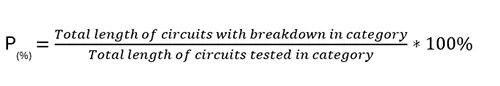
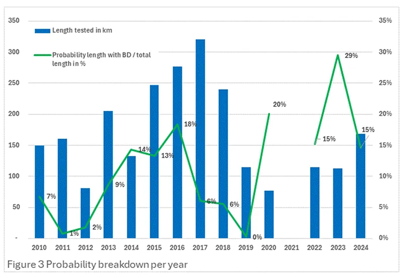
Fig. 3 presents the annual total length of circuits tested. The green line represents the calculated breakdown probability per year, derived by the length of circuits that experienced a breakdown divided by the length tested in that year. The overall average breakdown probability across all years is approximately 11%. However, the probability exhibits significant year-to-year variability, and no clear in- or decreasing trend can be observed. Therefore, the first research question—whether the number of breakdowns has decreased over time due to improved material quality and jointer expertise—cannot be clearly answered.
To address the second research question, the database was analyzed by voltage class, grouped into three categories: ≤ 110 kV, > 110 kV & < 220 kV, and ≥ 220 kV. Each class comprises a substantial total circuit length, ensuring statistically robust results, as illustrated in Fig. 4.
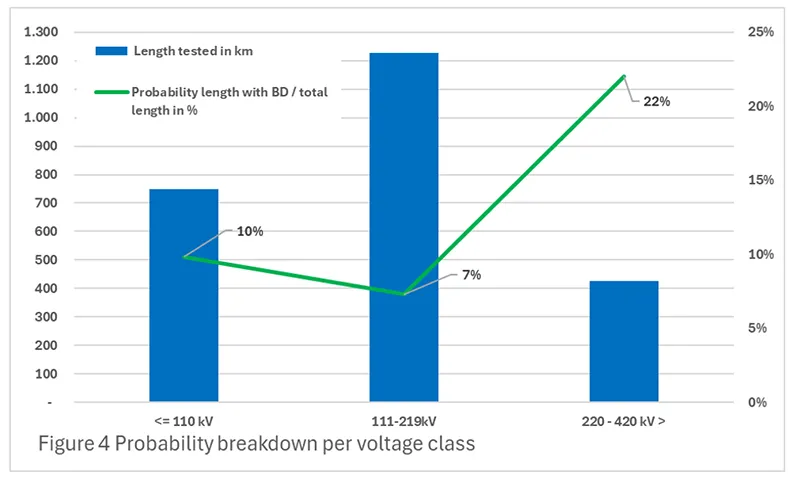
The breakdown probability for the two lower voltage classes ranges between 7% and 10%. In contrast, the ≥ 220 kV category shows a markedly higher breakdown probability of 22%. According to expert insights from KEMA Labs, this elevated risk at ultra-high voltages is primarily due to the increased electrical stress inherent to both cables and accessories in such systems. Even minor imperfections during the installation of joints and terminations—often carried out under suboptimal environmental conditions such as inadequate temperature control, high humidity, or dust exposure—can lead to failures. Lower voltage systems, by comparison, experience a lower less electrical stress due to the design, making them more tolerant to installation imperfections.
For the third research question, the database was segmented into 9 circuit length categories, each containing enough tested circuits to ensure statistical validity.
Fig. 5 displays a histogram of the number of circuits per length category, along with the corresponding breakdown probability (green line).
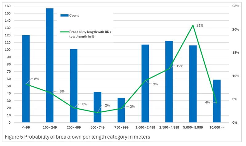
For circuits up to approximately 1 km, the breakdown probability ranges from 2% to 8%. However, for circuits between 5 and 10 km, the probability increases sharply to 21%. Expert interpretation suggests that shorter circuits (≤ 1 km) of the cable are typically delivered on a single drum / length and do not require joints. In contrast, longer circuits necessitate cable joints every ~1 km, and these joints are a dominant factor in breakdown occurrences. Thus, the longer the circuit, the more joints are required, increasing the likelihood of failure.
Interestingly, for circuits ≥ 10 km, the breakdown probability drops significantly to 4%. Further analysis revealed that these circuits are predominantly offshore cables, for example to offshore wind farms. These cables are typically manufactured in one-long length with factory-installed joints under controlled conditions and are fully tested before deployment via specialized cable-laying vessels. Despite the long length, these circuits only require locally installed terminations and no or very limited number of field joints. A second contributing factor is that very long cable circuits are typically rated at or below 150 kV, a voltage class associated with a lower breakdown probability, as illustrated in Fig. 4.
Partial discharge (PD) measurements were conducted on 653 out of the 838 circuits tested during commissioning. Among the 75 circuits that experienced electrical breakdown, PD testing was performed on 58. In 33 of these cases, PD activity was detected prior to breakdown. Notably, in several of these circuits, the PD level exhibited a gradual increase over a period of seconds to minutes leading up to the failure. In contrast, 25 circuits showed no detectable PD activity prior to breakdown, suggesting that the time interval between PD inception and breakdown was extremely short—possibly below the detection threshold (time-resolution) of the PD measurement system. Only 4 circuits exhibited measurable PD activity without experiencing breakdown during the 1-hour commissioning test. Subsequent inspection of the associated accessories, mainly joints, revealed small signs of degradation, likely due to minor installation defects.
Currently, there is insufficient reliable data on circuits that passed commissioning but subsequently failed shortly after being put into service. This limits the ability to draw firm conclusions about the predictive value of PD measurements for long-term reliability. However, it supports the recommendation in the standards to include PD measurements during commissions.

Conclusions & Recommendations
Breakdown Frequency & Trends
The annual number of electrical breakdowns per circuit kilometer tested exhibits significant scatter, with no discernible trend over the period analyzed. This suggests that the overall quality of cables, accessories, and—most critically—the installation practices have not demonstrated measurable improvement.
Voltage Class & Breakdown Probability
For cable systems rated below 220 kV, the probability of electrical breakdown ranges between 7% and 10%. In contrast, systems operating at 220 kV and 400 kV exhibit a significantly higher breakdown probability, slightly exceeding 20%. This disparity is attributed to the fact that higher voltage designs operate closer to the limits of material specifications. Consequently, even minor imperfections during accessory installation in the field are more likely to result in failure, whereas lower voltage systems are more tolerant of such deviations.
Circuit Length & Joint Influence
Cable circuits shorter than 2 km, typically consisting of a single cable section without joints, show a breakdown probability between 2% and 9%. However, as circuit length increases—necessitating one or more joints—the breakdown probability rises to approximately 20%. This underscores the critical role of joints as the most vulnerable component in cable systems. Even when joints are independently tested and certified, flawless installation remains essential. This requires both high expertise from jointers and optimal environmental conditions during installation.
Recommendations for Commissioning Practices
Based on the findings, it is strongly recommended that 1hr AC voltage commissioning tests be performed on all newly installed cable circuits. While partial discharge (PD) measurements can provide valuable insights into the integrity of the cable system, they should be considered complementary. PD testing cannot replace the diagnostic reliability of the 1-hour AC voltage withstand test.

References
[1] EXPERIENCE OF AC VOLTAGE TESTS WITH VARIABLE FREQUENCY USING A LIGHTWEIGHT ON-SITE SERIES RESONANCE DEVICE, W. Zaengl et all, Cigré, 1982
[2] IEC 62067 Ed. 3.0, “Power cables with extruded insulation and their accessories for rated voltages above 150 kV (Um = 170 kV) up to 500 kV (Um = 550 kV) – Test methods and requirements”, 2022
[3] IEC 60840 Ed. 5.0, “Power cables with extruded insulation and their accessories for rated voltages above 30 kV (Um = 36 kV) up to 150 kV (Um = 170 kV) – Test methods and requirements”, 2020