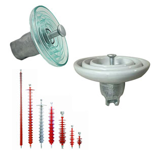
There are several alternatives when it comes to external insulation of EHV & UHV bushings, including porcelain, which can also be coated with RTV to improve pollution performance, a hybrid housing consisting of a porcelain core support with an HTM housing; or a fully composite housing.
This edited past contribution to INMR by A. Pastore of GE Vernova in Italy in co-operation with Alberto Pigini, compared performance of these alternatives in design aspects and requirements based on tests performed at laboratories worldwide.

Electrical Performance
In regard to electrical performance, the different insulation options for EHV & UHV bushings can be grouped into two main categories:
• HTM (hydrophobicity transfer material) insulators such as RTV silicone coated porcelain, hybrid solutions and composite solutions;
• non-HTM solutions, namely uncoated porcelain insulators.
Overvoltage Performance
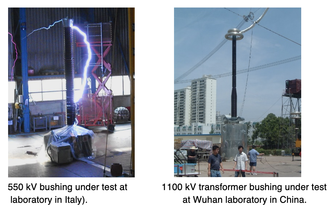
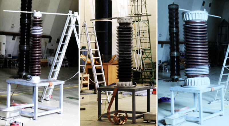
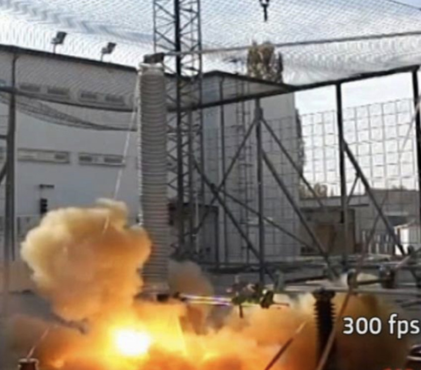
The most critical condition for external bushing insulation from the overvoltage point of view, although not commonly known, is represented by tests with Switching Impulses (SI) of positive polarity under rain. Examples of such test set-ups are shown in Fig. 1.
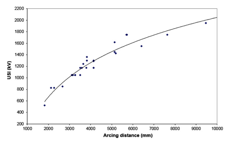
Flashovers under switching impulses develop mainly in air, unless the distance between sheds of the insulators being used is too small. Fig. 2 summarizes some test results obtained over the years. Due to the arc occurring mainly in air, testing found no significant difference between HTM and non-HTM insulation. Based on such broad test experience, design indications have been derived for internal product standardization from the switching performance point of view and bushing arcing distances have therefore been standardized based on SI level.
Pollution Performance
Performance Under AC Voltage
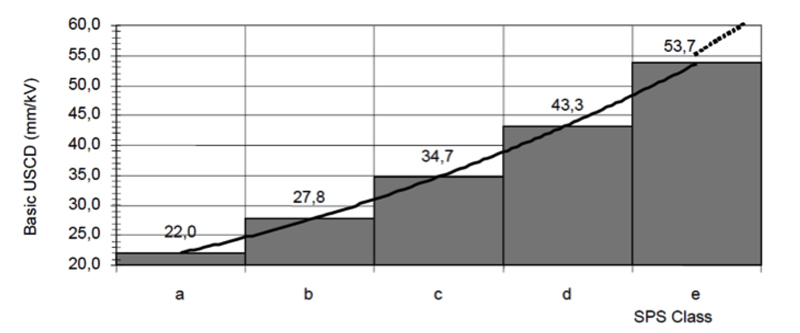
IEC 60815 TS Parts 2 & 3 offer guidelines for selection of insulators from the pollution point of view in AC. Basically, the same Unified Specific Creepage Distances (USCD) are indicated for non-HTM (e.g. ceramic) and HTM (e.g. composite) insulators, thereby making any deviations the responsibility of those who write the specification. Moreover, specifications generally assume that the same USCD is applicable to cap & pin insulators or station insulators having average diameter equal to or lower than 300 mm and indicating a correction of USCD only for large station insulator diameters.
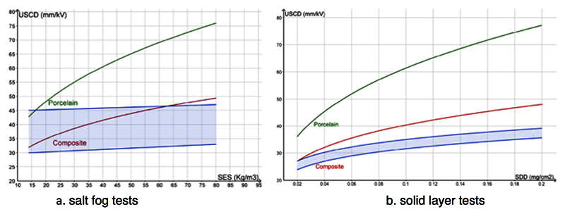
Applicability of the above indications in the case of non-HTM porcelain insulator housings was verified by performing ad hoc tests at a HV laboratory using Procedure B of the solid layer method. Fig. 4 provides results for the insulator housings shown in Fig. 5. These results were then compared with those following the indications as per IEC 60815 TS. A discrepancy can be noted, indicating that station insulators may require USCD higher than what is indicated in the standard, something that may need to be considered during its next revision. The same indications, namely a higher USCD is necessary for station insulators than for cap & pin insulators, were also found during related salt fog testing conducted in Italy and Mexico.
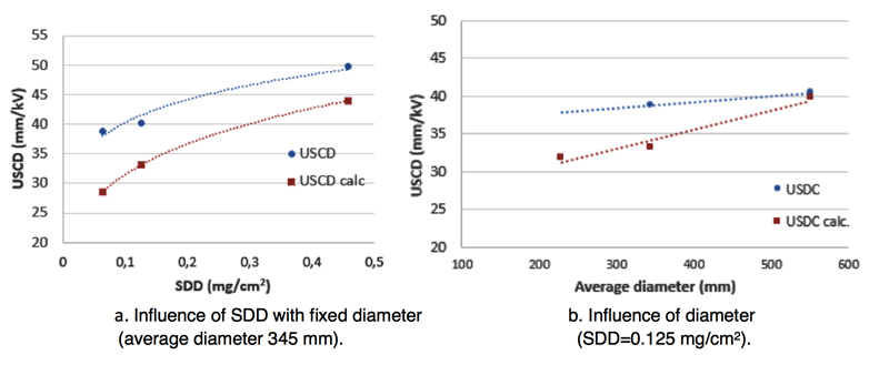
Tests to verify pollution performance of HTM insulators, i.e. composite housings, were carried out at a laboratory in Sweden. Given absence of a standardized test in this case, the salt fog method with quick flashover procedure was used. This allowed obtaining an indication of insulator performance after many surface flashovers, thereby conditioning the insulators and leading to an estimate of pollution performance that is closer to what might actually be encountered during long-term service (see Fig. 6).
At a salinity of 80 g/l, a USCD of 37 mm/kV was estimated, i.e. about 65% of the value estimated for ceramic housings based on a conservative estimate and considering that ceramic insulators may actually require higher USCD than in IEC 60815.

Performance Under DC Voltage
Guidelines for selecting insulators from the pollution point of view in DC are proposed in IEC 60815 TS Part 4, which gives design curves for both non-HTM and HTM insulators with reference to solid layer and salt fog parameters (shown in Fig. 7). As the case for AC, these curves are again assumed to be applicable both to cap & pin insulators and to station insulators with average diameter equal to or lower than 300 mm, with correction factors to be applied only for insulators of larger diameter.
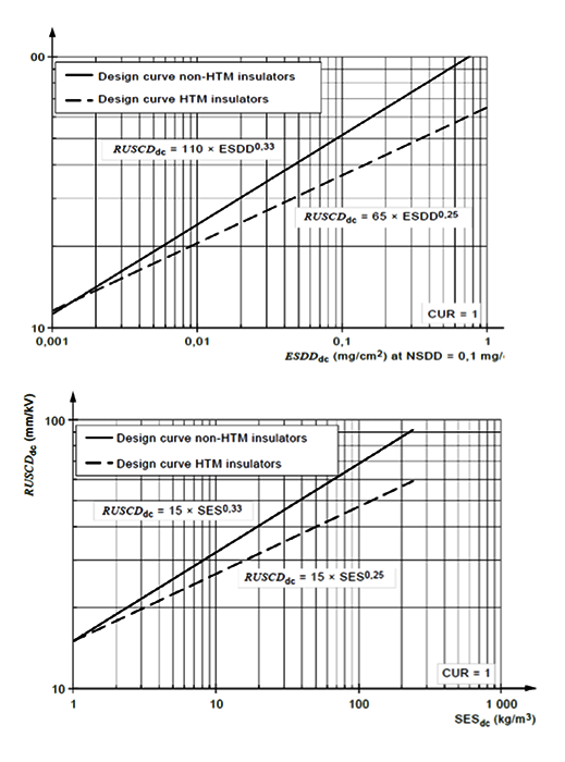
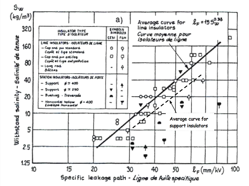
Fig. 8 compares the performance of line insulators and station insulators for the non-HTM case (i.e. ceramic insulators) using data from a past CIGRE paper and based on tests carried out in Italy and Germany. These indicate that direct application of line insulator data to station insulators has to be made with caution.
For station insulators, reference is made to maximum insulator diameter.
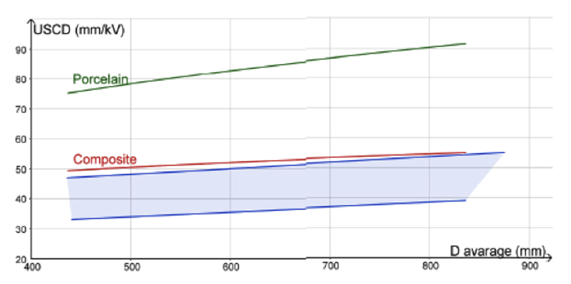
More recently, additional tests were made to compare experimental results with indications as per IEC 60815 Part 4 with special attention to HTM insulators. Again, in the absence of standardized testing methods, the quick flashover procedure was used for salt fog and the so-called ‘rapid procedure’ for solid layer. Experimental results of salt fog and solid layer pollution tests performed on composite housings of large diameter from different manufacturers (see Fig. 9 for an example) showed that results are influenced largely by insulator characteristics, as shown in Fig. 10. This however confirms need for a USCD much lower than for porcelain insulators, especially at relatively high contamination levels, with the ratio of USCD for composite versus ceramic insulators being less than 65%. Comparison of test results with IEC specifications therefore suggests that, in general, the IEC approach may be conservative in the case of HTM insulators.
Blue area: Range of experimental results for composite insulators.
Red & green lines: Design curve suggested in IEC 60815 Parts 2 & 3 respectively for composite and porcelain insulators
Fig. 11 shows that dependence of USCD on insulator diameter is much lower for HTM insulators than for ceramic insulators. This means the former offer greater advantage, especially for the larger diameter insulators typically required for UHV AC and DC applications.
Blue area: Range of experimental results for composite insulators.
Red & green lines: Design curve suggested in IEC 60815 Parts 2 & 3 respectively for composite and porcelain insulators

Design Indications
The above findings indicate that, looking only to withstand requirement under pollution, HTM insulators (and hybrid ones as well) could potentially be used with USCDs much lower than normally applied for porcelain, even if the final USCD selected for design must take into account the need to comply with long-term performance requirements (i.e. an ageing limitation). The advantages of HTM solutions in terms of pollution performance, especially for large diameter insulators required for the upper range of EHV and UHV, and the possibility with composite insulators to use efficient creepage factors higher than for ceramic equivalents, make the HTM solution (i.e. composite and hybrid insulators) the best candidate for AC applications in harsh environments. This also applies in general for DC applications (i.e. cases where performance under pollution conditions dominates design. Moreover, in the case of DC, hybrid insulator solutions are typically not used since the bushings are frequently placed at angles close to horizontal and a porcelain core is too heavy.
Icing Performance
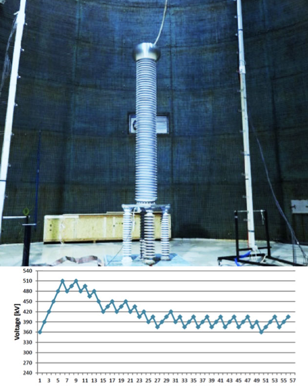
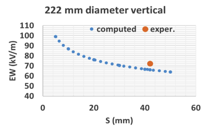
For some environments, insulator design must comply with expected performance under icing and sometimes under heavy ice conditions, i.e. with the insulator practically short-circuited by ice (i.e. the most critical case). Tests on HTM and non-HTM insulators were performed at three laboratories, with set-ups shown in Fig 11. Performance of HTM and non-HTM insulation was similar in spite of some possible initial advantage for non-HTM insulators during the initial phase of ice formation. Once an ice coating has formed, however, ice dominates insulation performance and fully masks insulator characteristics. Based on experience, a software tool for statistical design of insulators under heavy ice conditions has been developed. As example, Fig. 12 outlines maximum allowable stress for vertical insulators per m of arcing distance in the withstand condition versus ice thickness.

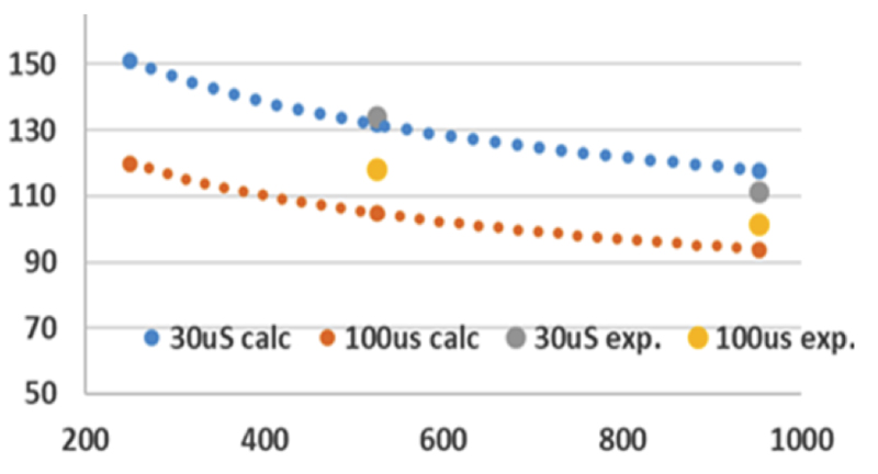
(water conductivity 30 µS/cm). DC voltage. Comparison of calculations with experimental results.
Much higher stresses can be allowed for inclined samples, as in applications such as wall bushings. Fig. 13 shows examples of calculations and comparison of experimental results for insulators inclined as per in-service conditions, where influence of insulator diameter is shown as well.
Seismic Performance
Earthquakes can be disastrous to the integrity of electrical grids and many studies have been carried out and are still in progress to limit these consequences. Bushings mounted on frames (i.e. transformers, reactors, GIS, walls) that amplify ground motion and being thin, high and heavy, are subject to even higher mechanical stresses than other grid components, especially in the EHV (420-550 kV) and UHV (≥800 kV) voltage ranges. As such, the critical components of a bushing are its condenser core and airside insulator. The first links mainly to insulation technology. Oil impregnated paper (OIP) insulation with condenser core made of paper impregnated with a fluid and all the components that hermetically contain the oil becomes more critical than solid resin impregnated paper (RIP) or resin impregnated synthetic (RIS) technologies, where no fluid is present. Second, since OIP technology was the first to have been developed, it is more traditionally associated with use of porcelain insulators. By contrast, the other ‘newer’ technologies are more frequently connected with use of HTM-composite insulators. Porcelain is heavy, rigid and fragile – all characteristics that are negative in terms of seismic withstand. Nonetheless, EHV and UHV bushings are typically OIP insulated and still equipped with porcelain insulators due mainly to the fact that utilities that use such bushings mostly favour traditional porcelain. Therefore, these must be carefully optimized for seismic performance by employing only highest quality materials (e.g. extra high strength porcelain, reinforced flanges, optimized cementing between porcelain and flange) as well as extensive use of FEM analyses along with subsequent seismic testing to verify simulation results.
Fortunately, UHV bushings are normally installed vertically – a condition that helps seismic withstand compared to the inclined position, where relevant dead load plays an important role in considerably increasing seismic stresses (see Fig. 14b). A mechanically optimized OIP UHV bushing (800-1100 kV) can normally withstand seismic acceleration of up to 0.3 g, corresponding to a medium level in IEC’s seismic standard where the lowest level is 0.2 g and the highest is 0.5 g (g being the earth’s acceleration of 9.81 m/s2). EHV OIP bushings can withstand a level of up to 0.5 g if placed vertically. In order to increase seismic withstand, both UHV and EHV bushings should ideally be equipped with composite insulators. In all of the above cases, a hybrid insulator solution would not help in terms of increasing seismic performance due to presence of the heavy porcelain core.
Solid insulation bushings equipped with composite insulators are seismically stronger because, in addition to their solid condenser core:
• the filler between core and insulator is normally dry (i.e. polyurethane foams or high viscosity gels) which act as damper between core and insulator, thereby increasing overall bushing damping;
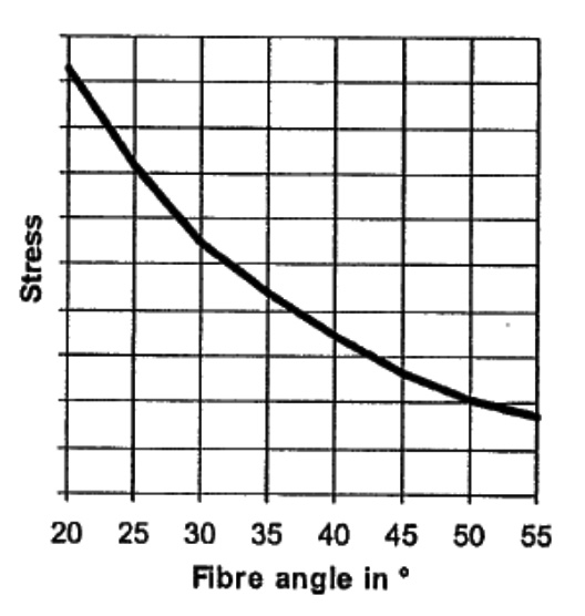
• a composite insulator is light, elastic and with good mechanical performance, which can be further increased by changing the winding angle of the fiberglass used in its hollow tube (see Fig. 15). While the standard winding angle is normally about 35 to 40° (with respect to insulator axis) this angle can be reduced thus increasing material properties by up to 50%;
• the bushing is lighter and consequently seismic acceleration generates a lower force (F = m x a);
• the insulator, in conjunction with filler, is an elastic system and therefore overall damping is lower. This reduces seismic response by decreasing maximum acceleration applied to the bushing;
• on the other hand, these classes of bushings, generally in the EHV range (420-550 kV), are frequently tested in an inclined position (see Fig. 14) where seismic stress is higher due to the dead load.
Dry bushings in the EHV range equipped with composite insulators can withstand the highest seismic level of 0.5 g, even in an inclined position and up to the worst angle of 45° (see Fig. 14a).
A final aspect to consider relates to direct moulding, a process that consists of moulding silicone sheds directly onto the bushing’s condenser core. This eliminates need for a composite insulator as well as the filler needed for the gap between insulator and fiberglass tube. This kind of bushing is structurally less strong and generally made only up to the HV range of 170 kV. Therefore, their mass is relatively small and seismic forces are not so high.

Safety Aspects
From the safety point of view, porcelain insulators, even if still the main type used worldwide, are critical due to risk of explosion in the event of internal flashover that comes into contact with the body. The thermal shock from the arc generates a dangerous explosion with projection of sharp chunks of porcelain all around and possible serious injury to persons and damage to nearby equipment. This is one of the reasons why porcelain insulators are progressively being substituted with composite insulators that do not suffer this type of violent phenomenon. In case of internal arc, the composite insulator breaks but does not explode. This is another positive characteristic for such insulation, in addition to the pollution and seismic performance advantages outlined above. A hybrid insulator solution is not used when focused on the safety aspect since the drawbacks of porcelain in terms of explosion risk do not change.
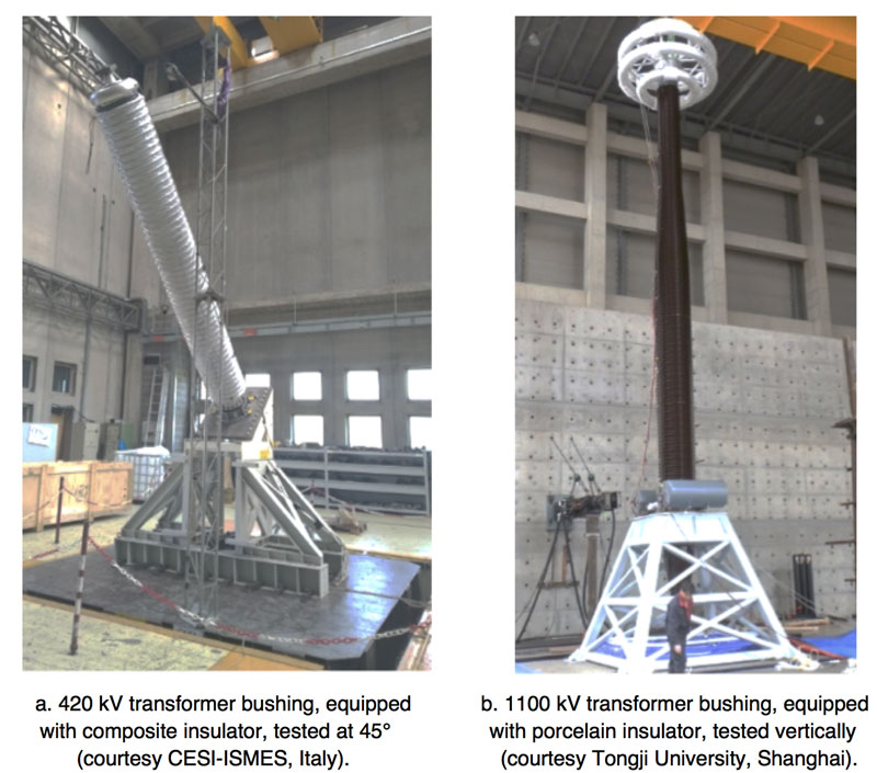
One of the latest developments in OIP bushings, traditionally equipped only with porcelain, has been to offer them in the EHV range with composite insulators instead. This avoids the possible drawbacks of porcelain while maintaining known, reliable OIP technology and is a compromise being considered by more and more utilities in recent years. For example, to demonstrate the explosion proof capability of such bushings, Italian TSO Terna recently introduced the internal arc test, typically used for years in the case of current transformers. The goal is to verify that when a 420 kV bushing is run with a current of 63 kA for half a second there is no projection of solid parts outside a radius of 2 m from the bushing’s airside axis. This test has been carried out with success for 420 kV class transformer bushings using both insulating technologies, OIP and RIP (see Fig. 16).
Another important safety aspect relates to the possibility to reduce risk of fire not only of the bushing in case of flashover but also of the transformer itself. An OIP bushing contains a flammable fluid that can burn in case of internal arc. Due to its structure, if a component such as an insulator breaks following flashover, it loses its tightness can allow transformer oil to exit through it, leading to possible worst case burning of the transformer. Use of dry type bushings reduces such risk because the bushing, being a single-piece, acts as a cap on the transformer. Even in case of internal damage, spill of transformer oil is avoided reducing fire risk.

Conclusions
The behaviour of non-HTM (porcelain) and HTM (composite and hybrid) insulators was analysed from different points of view. In terms of wet switching impulses performance, there is no appreciable difference because the flashover happens mainly in air following the water flow. IEC Standards specify the same USCD for HTM and non HTM insulators, cap & pin and station types, introducing only a correction factor for average diameters larger than 300 mm. Tests carried out in AC at different laboratories using the solid layer as well as salt fog methods demonstrate to the contrary that performance of HTM insulators is significatively better than for porcelain and that line insulators require a USCD lower than necessary for station insulators. This should be considered in any IEC Standard revision.
For DC voltages the IEC Standard confirms the same concept. Again, experimental results using salt fog and solid layer methods demonstrate that the behaviour of HTM insulators is remarkably better than non-HTM insulators. This phenomenon becomes more pronounced with larger diameters and in this case cap & pin types behave better than station insulators.
Under icing conditions, especially when the ice layer becomes thick, behaviour in AC and DC of HTM and non-HTM insulators is basically the same because conduction phenomena are dominated by ice, thereby completely masking insulator surface.
Seismic withstand is critical for all bushings, especially in the UHV range. OIP insulation and porcelain are typically the main type used and all components must be optimized to realize a bushing that is seismically resistant. Dry bushings equipped with composite insulators have superior behaviour under seismic stresses as well as in terms of safety. Composite insulators do not explode in case of internal flashover whereas non-HTM insulators, both porcelain and hybrids, have risk of explosion. Moreover, dry bushings help to contain transformer oil and therefore help decrease risk of fire compared to OIP bushings.

References
[1] IEC 60815 TS Part 2 – Selection and dimensioning of high-voltage insulators intended for use in polluted conditions – Ceramic and glass insulators for a.c. systems.
[2] IEC 60815 TS Part 3 – Selection and dimensioning of high-voltage insulators intended for use in polluted conditions – Polymer insulators for a.c. systems.
[3] A. Pigini and al., “Disconnector design from the pollution point of view”, paper submitted for publication.
[4] P. Lambeth e C. De Tourreil, “Electrical performance measurements of artificially and naturally aged polymeric insulators”, International conference on overhead line design and construction: Theory and practice, London, 1988.
[5] G. Pirovano, P. Omodeo Gianolo, A. Pigini, “Assessment of the pollution performance of composite insulators”, ISH 2013
[6] IEC 60815 TS Part 4 – Selection and dimensioning of high-voltage insulators intended for use in polluted conditions – Insulators for d.c. systems.
[7] R. Cortina, G. Marrone, A. Pigini, L. Thione, W. Petrusch, M. P. Verma “Study of the dielectric strength of external insulation of HVDC systems and application to design and testing” Cigre general session 1984, paper 33.12.
[8] CIGRE WG C4303, “Artificial Pollution Test for Polymer Insulators. Results of Round Robin Test”, CIGRE Brochure 555-2013, 2013.
[9] G. Testin, M. Boutlendj, P. Cardano, A. Pastore, M. Saravolac, M. Sehovac, A. Pigini “Methodologies for pollution tests on composite housings”, Cigre General Session 2016, Paper A3-115.
[10] A. Pigini, “Design and testing of polymeric insulators to verify the pollution performance under DC voltage”, INMR World Congress 2015.
[11] P. Cardano, M. Nosilati, E. Stella, V. Girlando, G. Testin, M. Saravolac, A. Pigini, A. Dariani, S. Yuan, “Station insulation performance under heavy icing conditions”, Cigre General Session 2016, Paper B3-304.
[12] A. Pigini, R. Cortina, M. Marzinotto, G. Lagrotteria, “Line insulator performance in presence of ice and snow”, ISH 2017
[13] P. Cardano, G. Testin, V. Fogliani, A. Pastore, M. Sehovac, “Development of UHV bushings for extremely severe seismic conditions”, INMR World Congress 2017.
[14] G. Testin, P. Cardano, M. Sehovac, M. Boutlendj, A. Pigini, “HV & UHV bushings design optimization from safety point of view”, INMR World Congress 2013.