Porcelain and glass strings have been widely used for suspension applications on UHV DC projects in China due to their mechanical and electrical properties as well as the depth of local operating experience with such insulators. However, about 15 years ago reports started to be received of hardware corrosion problems affecting large numbers of porcelain string insulators installed on early ± 800 kV lines. These problems included corroded iron caps on insulators located at the negative polarity and corroded pins on insulators at the positive polarity.
The corrosion mechanism was closely studied and tests as well as simulations were carried out. Results indicated that corrosion on caps could increase contamination accumulation on insulator surfaces and decrease flashover voltage. Pin corrosion could decrease mechanical strength. This edited past contribution to INMR by Prof. Wang Liming of China’s Tsinghua University, proposed solutions.

The scale of China’s power grid has increased rapidly as has development of the country’s UHV DC technology. Numerous projects have already been put into operation and are now optimizing allocation of the country’s energy resources. Early such projects included the ±800 kV Chusui Line, from Yunnan to Guangdong, and the Xiangshang Line, from Yunnan to Shanghai, both commissioned in 2010. Starting October 2011, however, corrosion phenomena were reported on the hardware of many porcelain and glass insulators on these lines. The number of iron cap corroded insulators on Chusui Line was more than 24,000 according to inspection results while over 2000 corroded insulators were discovered on the Xiangshang Line by March 2012.
With increasing operating time, the number of insulators having hardware corrosion problem also increased and this was deemed to threaten security and stability of the power system. Subsequently, 82 porcelain and glass disc insulators suffering from pin corrosion were randomly retrieved from the positive polarity of the Chusui Line in March 2013.

Causes of Corrosion
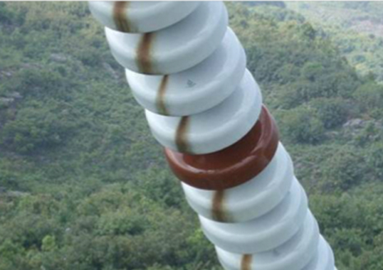
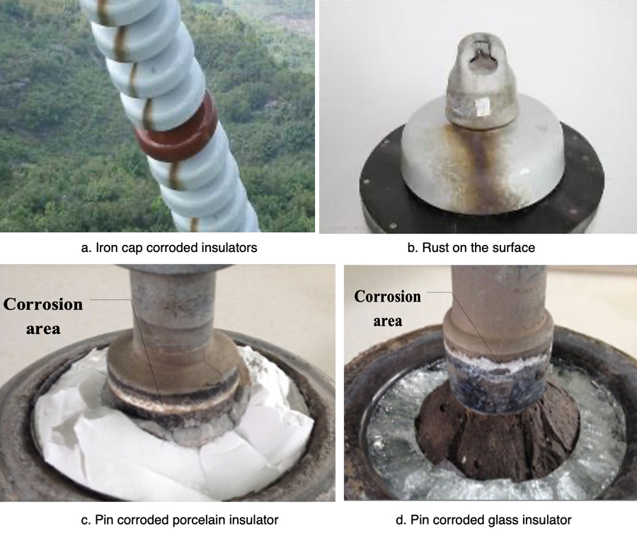
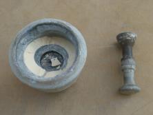
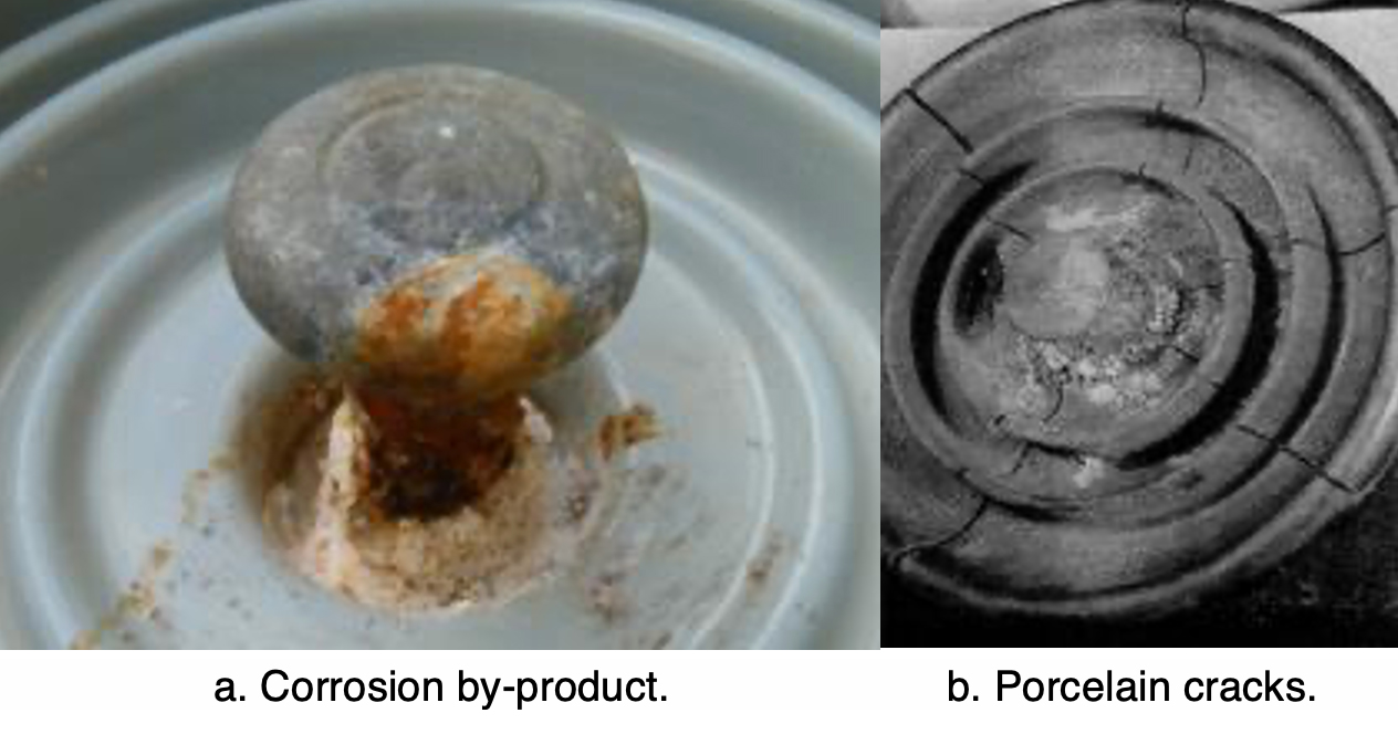
Corroded porcelain and glass insulator samples were hung in a V-string with cap-corroded insulators located at the negative polarity and pin-corroded ones concentrated at the positive polarity. The corrosion area of iron caps was typically the lowest part and there was an obvious rust channel on the insulator surface (as shown in Figs. 1a and 1b). In the case of pin-corroded insulators, the corrosion area was mainly the annular region at the cement-zinc sleeve interface (as illustrated in Figs. 1c and 1d). Moreover, the lowest portion of the zinc sleeve corroded more seriously than other parts.
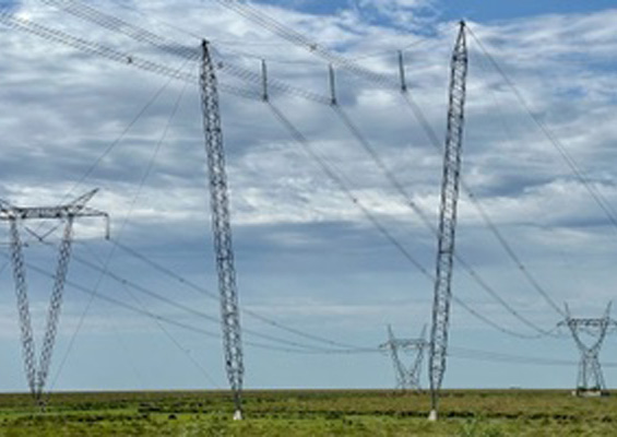
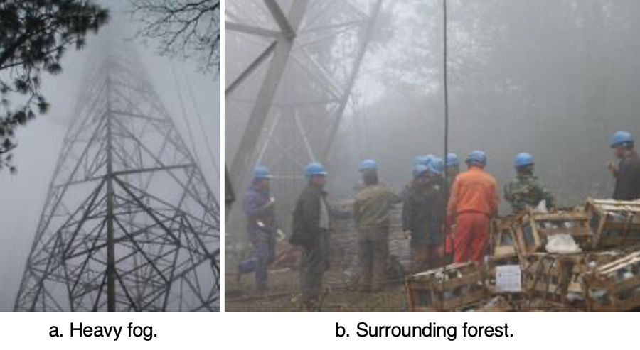
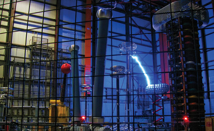
Electrolytic reactions play a major role in the corrosion process due to the polarity phenomenon affecting hardware. Insulators that corroded most seriously were locates in forested areas where humidity is high and there is often continuous heavy fog in late autumn, winter and early spring. For example, the environment surrounding tower #407 on the Chusui Line is shown in Fig. 2.
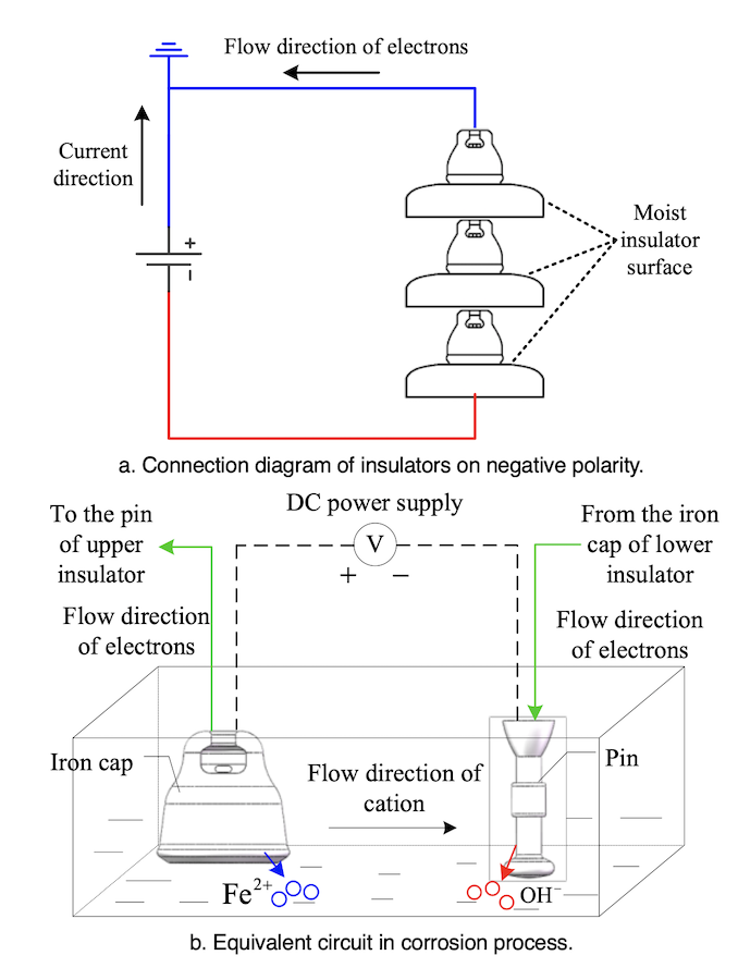
The principle behind electrolytic corrosion of iron caps is shown in Fig. 3. The electrolytic loop here consists of a DC power supply, hardware and electrolyte. The iron cap connected to the positive side (ground side) of the power supply is an anode whereas the pin connected to the negative side is the cathode. Ferrous ions are formed by oxidation reaction of the iron cap whenever the insulator surface becomes damp.
Fe→Fe2++2e–
H+ and OH– ions exist in the electrolyte as a result of water ionization and a reduction reaction occurs on the cathode side. Cations migrate to the cathode and anions moves to anode under applied DC voltage. Precipitates are formed by Fe2+ and OH–. Due to the existence of oxygen in the solution, a further oxidation reaction can take place. The constituents of rust are shown as:
mFeO+nFe2O3+pH2O
where the values of m, n and p vary under different temperatures, pH values and oxygen contents.
Simulation Test Method
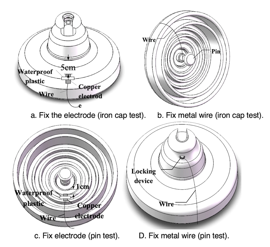
The spray water method was used to simulate the corrosion process affecting insulator hardware. Before the test, the copper electrode was fixed onto the surface of insulators. The distances between electrode and insulation element (i.e. porcelain or glass) were about 5 cm and 1cm for iron cap & pin tests respectively (see Figs. 4a and 4c). The metal wire connected to the other end of the copper electrode was fixed on the pin and locking device for the iron cap & pin tests respectively (see Figs. 4b and 4d).
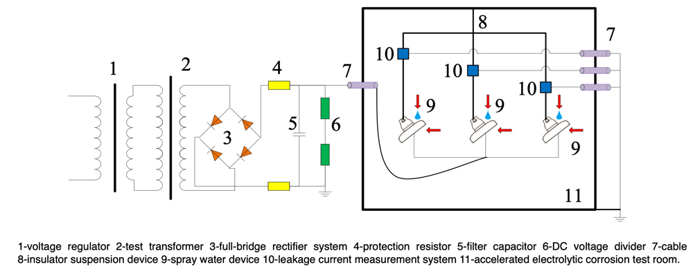
During the test, an NaCl solution was sprayed onto the insulator surface to form the electrolyte. For the iron cap test, the voltage applied to the pin was in the range -0.8~-1.5 kV, the iron cap was grounded and the conductivity of the NaCl solution and its spray velocity were 8~10 mS/cm and 8~10 L/h respectively. For the pin corrosion test, the voltage applied to the pin was in the range of +0.4~+0.8 kV and the iron cap was grounded. Conductivity and spray velocity were 2~3 mS/cm and 2~3L/h respectively. The experimental set-up is shown in Fig. 5.

Influence on Mechanical & Electrical Characteristics
Iron Cap Corrosion
Three pieces of iron cap corroded porcelain insulators retrieved from tower #407 of the ± 800 kV Chusui Line were used to carry out a contamination degree measurement. The surface of these insulators was divided into three parts: one was the region with accumulation of corrosion by-products on the upper surface (area A); another was the area with no corrosion by-products on the upper surface (area B); the third was the lower surface (area C), as shown in Fig. 6. Measurement results are presented in Table 1.
Results indicated that ESDD and NSDD of area A were much higher than those of areas B and C, i.e. the contamination degree of the rust channel area was higher than for other areas.
Pollution Flashover Testing
The negative and positive polarities of the ± 800 kV Chusui Transmission Project were put into operation in June 2009 and June 2010 respectively. While this transmission line had not experienced any flashover incident, there were reports of discharge phenomena in Aug. 2011 at the negative polarity on tower #407. For example, sparks could be seen and there was resulting noise. The XZP2-300 type porcelain insulators on this particular structure had experienced corrosion early on and were already seriously corroded. As such, each February or March during annual maintenance with the line out of service every suspension type insulator was replaced. Therefore, flashover tests conducted on samples removed from this tower reflected their condition after one-year of service.
Pollution flashover tests were carried out in a 26m × 26m × 30m fog chamber with maximum output voltage of DC power supply being 1000 kV. Four groups of XZP2-300 type porcelain insulators removed from the Chusui Line were used to conduct these tests. Groups 1 and 2 were retrieved in March 2013, while Groups 3 and 4 in March 2014. Groups 1 and 3 consisted of 14 iron cap-corroded insulators, and Groups 2 and 4 were made up of 14 pin-corroded insulators. These were hung in a V-string (76°) with each side made up of 7 insulator discs. The boost voltage method was used to conduct the flashover test and the flashover time of each group was 6. Test results are presented in Table 2.
Findings showed that the flashover voltage of iron cap-corroded insulators was 20% lower than that of pin-corroded insulators. Moreover, in order to analyze the cause of the heavier pollution concentrated in the rust channel area, the conductivities of solutions with different masses of rust were measured and compared with the same mass of NaCl.
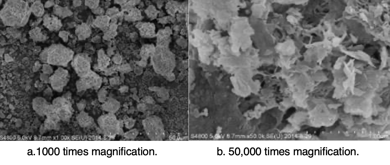
It can be seen from the results (see Fig. 7), that rust is not soluble in water and has little influence on conductivity of the solution. Rather, the high pollution degree at the rust channel area is caused by the rough surface, making cleaning of contamination more difficult. The micromorphology of iron cap corrosion by-products is shown in Fig. 8.

Influence of Pin Corrosion
Mechanical Stress Calculation
The XZP2-300 type porcelain insulators on tower #407 of the Chusui Line were used for simulation by means of the FEM method. These porcelain insulators were hung in double V-strings (76°) with each string made up of 69 units. The transmission line employs six-bundle LGJ-630/45 type aluminum steel reinforced (ACSR) conductor. Referring to standard GB/T 1179-2008, the diameter of each wire is 33.8 mm and its mass 2079.2 kg/km. The span between adjacent towers is 500 m and maximum conductor sag is 19 m so that actual length of wire between two towers is 501.8 m. Each tower bears the wire weight of the span evenly, namely:
![]()
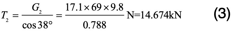
The static tension that insulators bear in each string is:
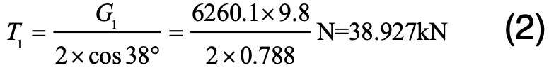
The weight of each XZP2-300 type insulator is 17.1 kg. The first insulator counted from the cross-arm bears the maximum static tension:
As such, the total static tension on this insulator is:
![]()
Calculation results of mechanical stress and strain on the first insulator from cross-arm are shown in Fig. 9.
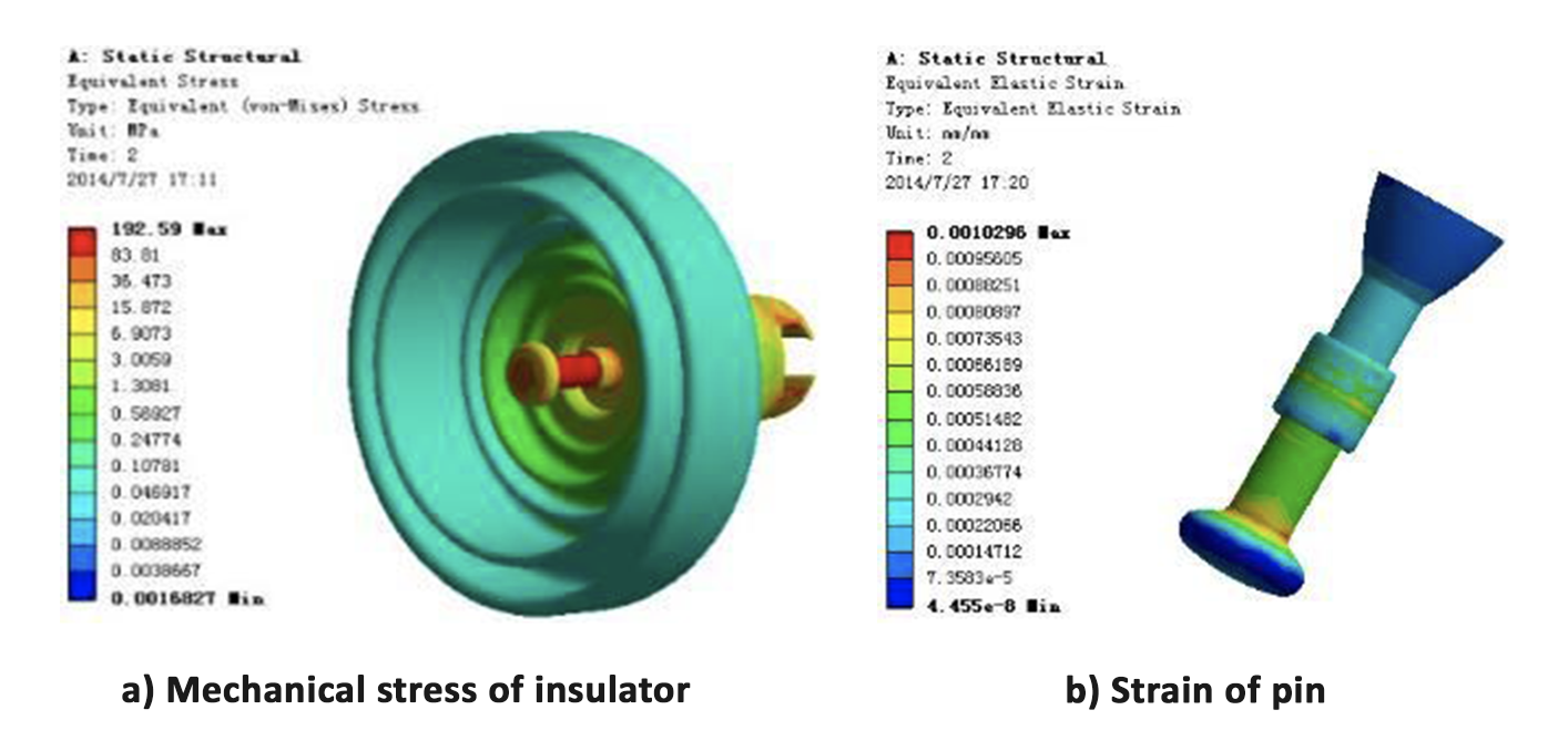
Fig. 9 shows that, in the case of the pin, the part exposed to air and the cement-zinc sleeve interface experience great strain under the stress. If the cross-section of this pin is reduced due to corrosion, the portion exposed to air is easy to pull off. Similarly, if the adhesive strength between pin and cement decreases due to expansion from corrosion by-products, the entire pin could be pulled from the iron cap.
Mechanical Tensile Failure Test
Mechanical load test in accordance with Chinese National Standard GB/T19443 were carried out on XZP2-300 type porcelain insulators, including new production units, cap-corroded units and pin-corroded samples. In terms of new XZP2-300 type porcelain insulators where rated mechanical failure load is 300 kN, the failure load of these insulators fell mainly in the range of 380~410 kN. But for pin-corroded insulators with less than 4 years of service, the final failing load was in the range of 340~370 kN. Final failure mode is shown in Fig. 10.
Test results indicate that, even in the case of pin-corroded insulators where the zinc sleeves have not been penetrated and pin cross-section has not been reduced, mechanical strength decreases. This is because hoop stress at the cement-zinc sleeve interface weakens the strength of the bond between them (see Fig. 11).

Remedial Solutions
Solution for Corroded Caps Still In-Service
A U-shaped zinc ring has been designed to suppress electrolytic corrosion of the iron cap of those insulators in service. as shown in Fig. 12.
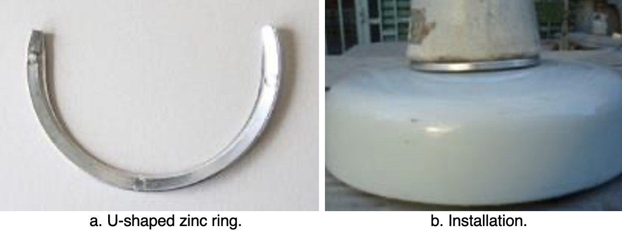
To verify the effectiveness of this zinc ring, XZP2-300 type porcelain insulators were used to conduct accelerated corrosion test with the spray water method, intended to simulate electrolytic corrosion. The iron caps were grounded and the voltage applied to pins was during the accelerated corrosion test was -0.8~-1.5 kV. Test insulators were hung in a 76° V-string – the same as on the actual transmission line. During the corrosion simulation, the electric charge quantity was set as 81,000 C, based on the maximum average annual amount of corrosion charge (i.e. 2618 C/year) obtained from the Chusui Line and given the insulator’s expected 30-year service life. The respective insulator sections with the biggest depth of corrosion in their iron caps, both with and without the zinc ring, are illustrated in Figs. 13 and 14.
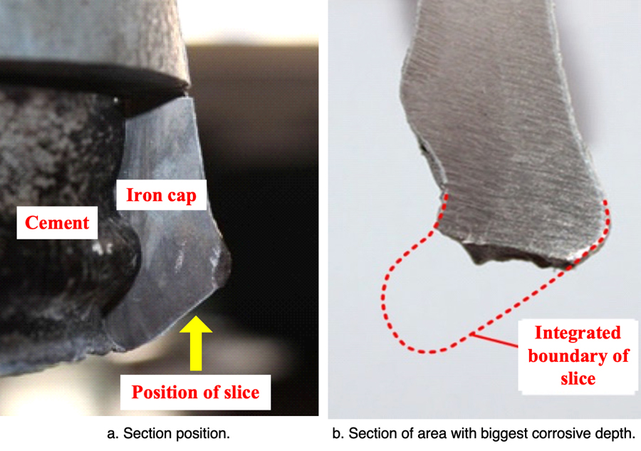
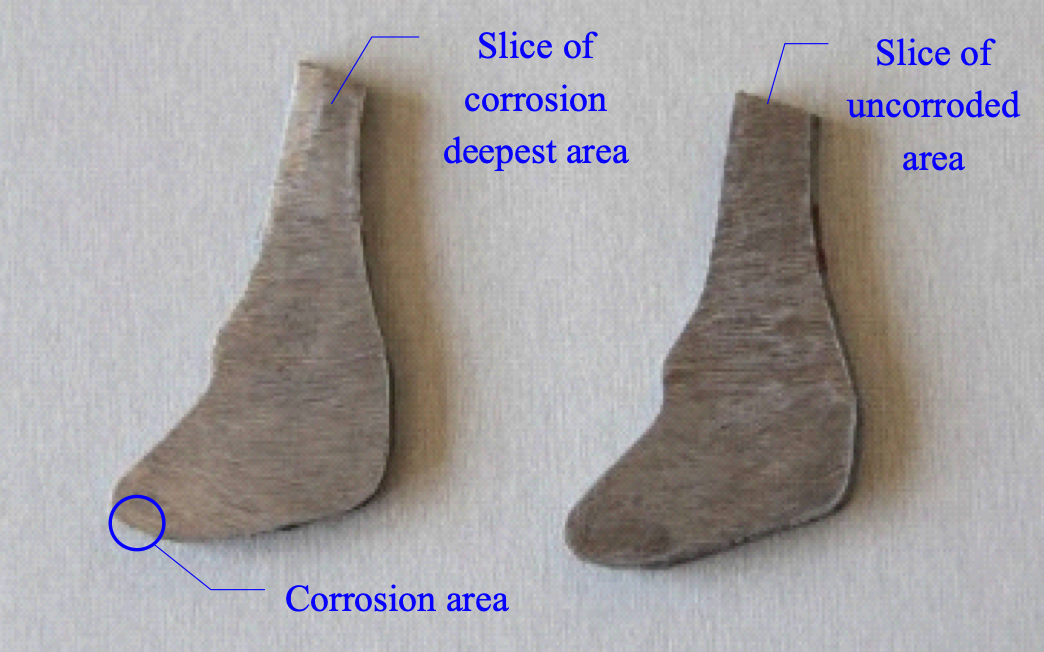
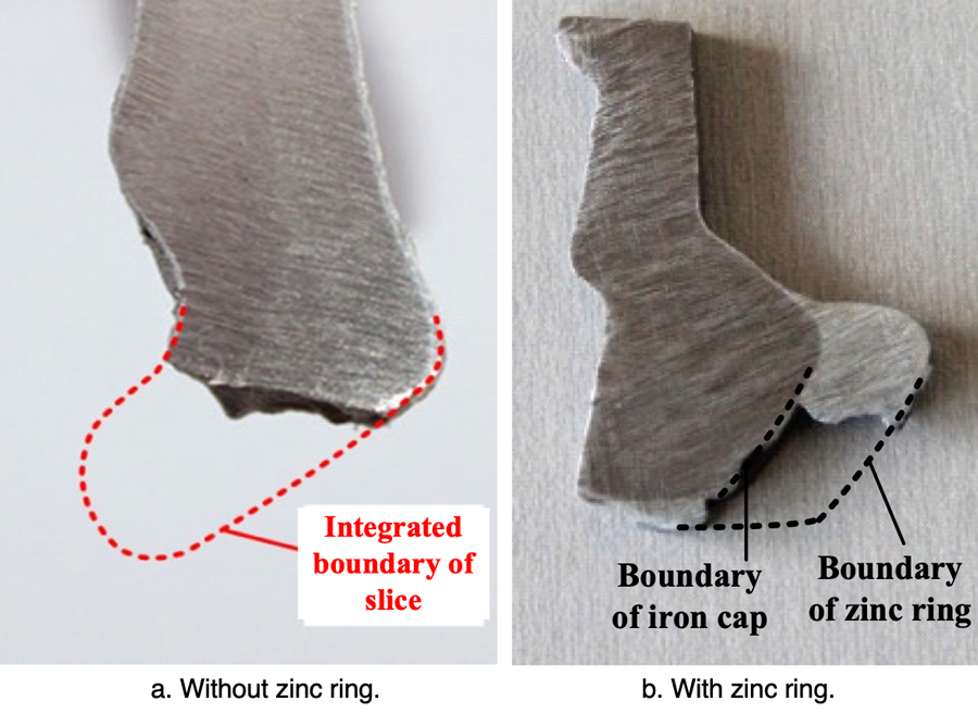
Corrosion depth of the iron cap without a zinc ring is quite large. However, after installation of the ring, the section with the deepest corrosion is almost the same as that of the non-corroded area. Therefore, installing such a U-shaped zinc ring is deemed effective in suppressing further electrolytic corrosion of iron caps.

Solution for Cap Corrosion on New Insulators
In the case of new insulators, a zinc ring attached to the iron cap has been designed to suppress electrolytic corrosion (see Fig. 15). The structure and size of these rings were optimized according to test results from sample insulators.
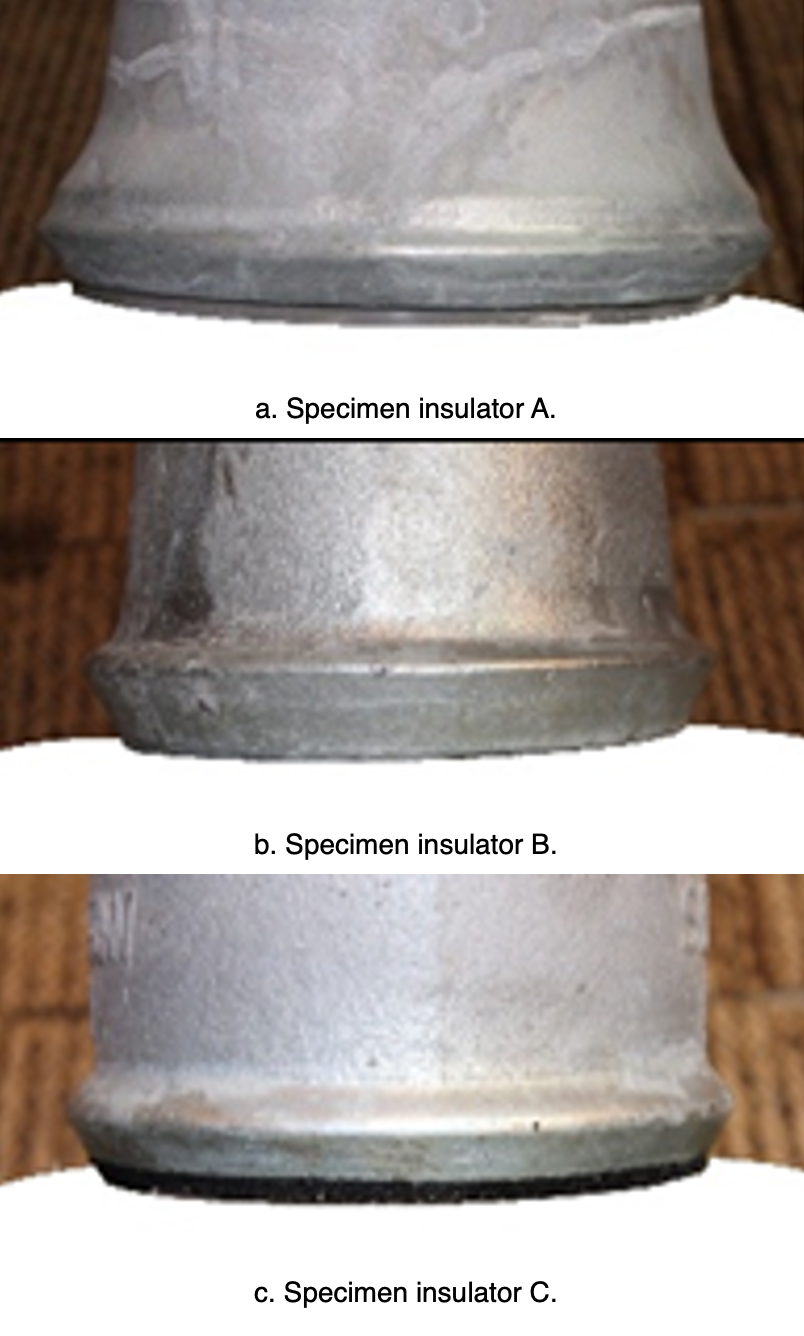
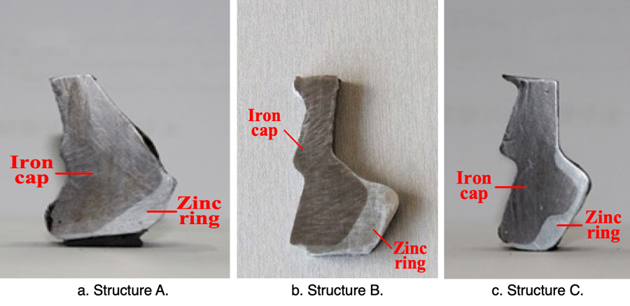
In the simulated corrosion, the electric charge quantity was set as 45,000 C. The respective sections with the highest depth of corrosion in caps, with and without a zinc ring, are illustrated in Fig. 17.

Solution for Corroded Pins
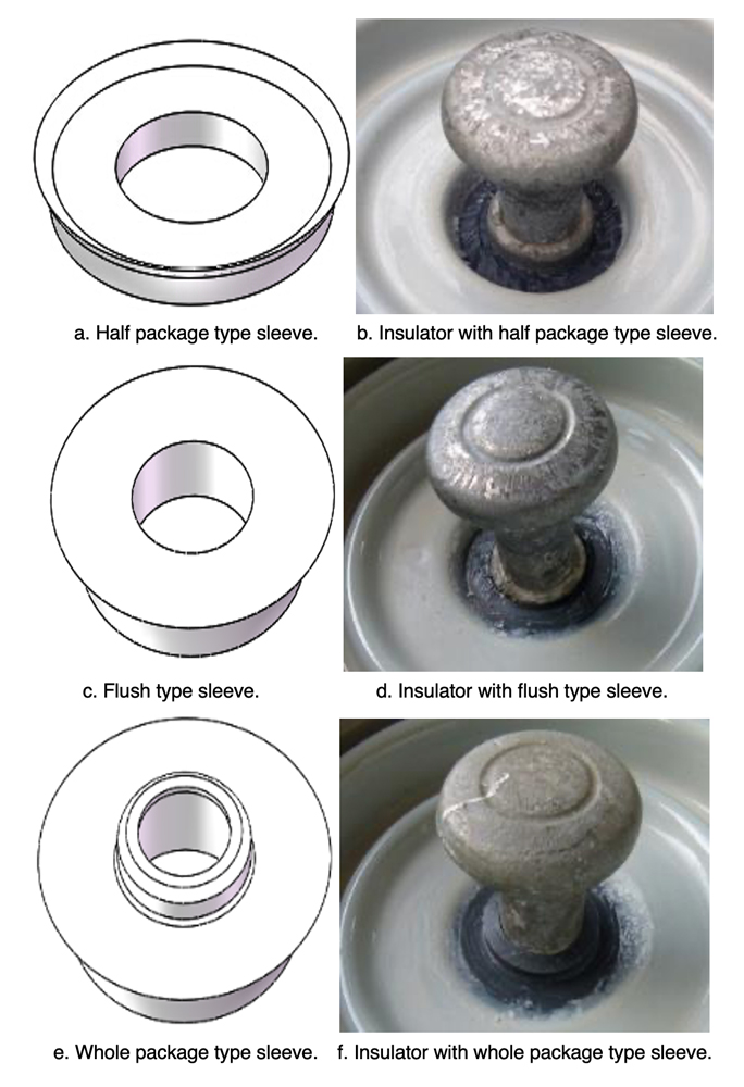
Based on the research described earlier, mechanical strength of insulators in services decreases even if their pins are not corroded and become thinner since expansion caused by corrosion by-products reduces bonding strength between cement and zinc sleeve. Thickening the zinc sleeve is therefore not effective here and the recommendation is rather to install an organic material sleeve onto the zinc sleeve (as in Fig. 18). Such an organic sleeve can be manufactured with either of two types of material: one a high temperature vulcanized (HTV) silicone rubber; the other a semi-conductive rubber made by adding conductive carbon black to HTV silicone rubber. This sleeve alters the corrosion process, effectively shifting the corroded area from the cement-zinc interface to the exposed portion of the zinc sleeve that does not bear any hoop stress, and avoids any decrease in bond strength between cement and zinc sleeve. Improved suspension disc insulators having these organic sleeves are then used mainly in regions with high humidity and serious pollution. For XZP2-300 type porcelain disc insulators, units having ‘half package’ type, ‘flush’ type and ‘whole package’ type organic sleeves installed are designed as shown in Fig. 19.

Tests using the water spray method were conducted on XZP2-300 type porcelain insulators having different organic sleeves installed. Electric charge quantity was set as 45,000 C, based on maximum average annual amount of corrosion charge on the Chusui Line (1500 C/year) and the 30-year expected service life of insulators. A 1000-kg cement block was then hung on these insulators for 6 months after which they were exposed to a tensile load test in accordance with Chinese National Standard GB/T19443. Tensile failure load and pins are shown in Figs. 21 and 22.
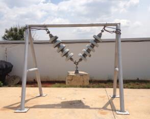
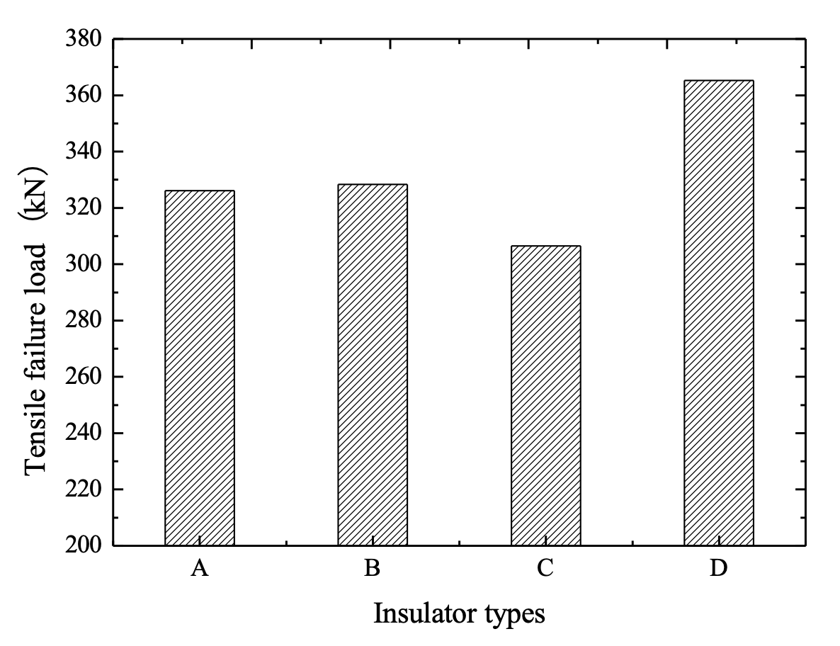
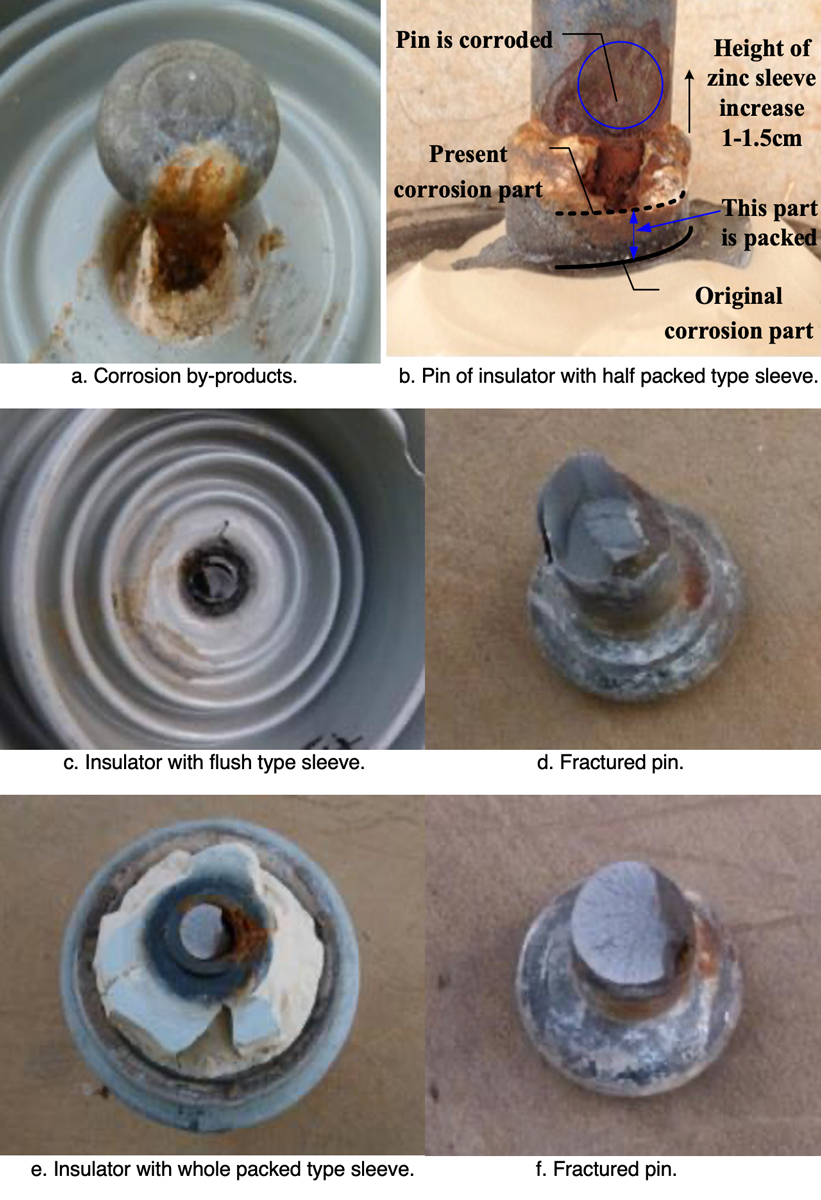
Fig. 22b confirms that installing the half package type organic sleeve alters the corrosion area on the zinc sleeve. The original corroded part of the cement-zinc sleeve interface bears radial stress whereas the new area of corrosion is the exposed portion of the zinc sleeve that does not have to withstand hoop stress. As such, expansion from corrosion by-products cannot have an adverse impact on insulator mechanical strength. Test results (see Fig. 21) verify the effectiveness of a ‘half package’ type organic sleeve. However, corrosion on pins with flush type as well as whole package type sleeve installed can reduce pin cross-section and decrease mechanical strength. Moreover, test results indicate that the part of the zinc sleeve between the two lines is packed by the organic sleeve and cannot be used as a sacrificial electrode to protect the pin. In other words, installation of the half package type organic sleeve can reduce the effective size of the zinc sleeve and lead to pin corrosion, as evident from the blue circle in Fig. 22b. In order to overcome this problem, it is recommended to increase the height of the exposed part of the zinc sleeve by 1~1.5 cm, based on existing height.
Conclusions
1. Hardware corrosion phenomena have occurred on ± 800 kV UHV DC transmission lines due mainly to electrolytic corrosion.
2. Iron cap corrosion can lead to more contamination accumulating on the insulator surface and decrease flashover voltage of the entire string.
3. Pin corrosion can reduce the mechanical strength of the insulator.
4. Zinc rings and U-shaped zinc rings can be used to suppress cap corrosion on new as well as on those insulators already in service.
5. Installing an organic material sleeve can solve the problem of decreased mechanical strength caused by expansion of corrosion by-products.