Insulators, whatever the material, are tested to better predict behavior in the field throughout their service life. While the best measure is actual field experience, it is impractical to build this for every different design or iteration. It is therefore necessary to understand the key factors that influence performance of a transmission line and its components in order to best assess the competence of any specific insulator design and material. For example, design testing of polymeric type insulators originally focused on evaluating the characteristics required of every effective insulator, i.e. dielectric strength, environmental stability, resistance to tracking and erosion, UV resistance and thermal stability. However, testing expanded into also verifying specific material properties such as hydrophobicity, flammability and resistance to the impact of corona.
This edited contribution to INMR by Jeff Butler of Hubbell Power Systems in the United States discusses different aspects of insulators that should be considered when trying to optimize line design, construction and operation and presents a case study of how this was done for one particular 500 kV line.
Power grids must address unique challenges that threaten performance of transmission lines. For example, it is important to understand the impact of pollution, both human-caused and natural. Moreover, it is also necessary to look at influence of humidity. There are two specific aspects when considering impact of environmental pollution: if contamination is corrosive, traditional insulator construction methods based on hot dip zinc galvanizing may be at risk. The second and more universal concern is presence and level of airborne contaminants that accumulate on insulator surfaces.
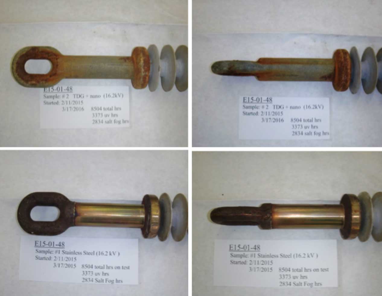
The main focus when addressing concern of corrosion of insulators is on the ferrous material used in connecting to hardware and end fittings. In the case of ceramic bell/disc type insulators, life of hardware can be extended by increasing the presence of sacrificial zinc, either through reinforced galvanizing or by addition of zinc sleeves. Polymeric insulators allow additional options. For example, stainless steel could be considered against corrosion with typically 10 times the performance of hot dipped galvanizing (HDG).
Testing, however, has shown that use of stainless steel threatens the ability to maintain an effective end fitting seal as well as the crimping properties that protect the insulator. A better option therefore would be use of ferrous end fittings and hardware but with thermal diffusion galvanizing (TDG) rather than standard HDG. For example, tests conducted at Hubbell Power Systems have suggested that TDG protection levels against salt corrosion are similar to stainless steel 304 (see Fig. 1) yet TDG does not affect the material properties needed to maintain an effective seal. The TDG option is also more economical than stainless steel and more environmentally friendly versus HDG.
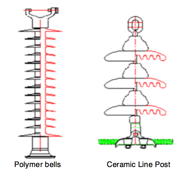

The second principal concern for service areas with contamination that deposits onto surfaces is the ability of an insulator to defend itself against the impact. Leakage and creepage are a measure of the distance along the surface of the insulator between metal end fittings (see Fig. 2). Using air as insulating medium across an insulator, contamination that collects along its surface can create conductive paths that reduce effective leakage distance. This risks compromising performance.
Standards such as IEC 60815 aim to provide guidance for each applicable pollution level (see Table 1). Previously, IEC 60815–1986 used a basis of line-to-line voltage and a distance ratio of mm/kV to define leakage distance and pollution class. Subsequently, IEC 60815–2008 attempted to clarify this ratio by relating it to line-to-ground voltage and also added an additional class distinction. This way, standards attempt to establish a more universal basis for comparing pollution classes. However, this also leads to the challenge of how best to define the correct pollution class for any particular service environment.
Empirical evidence serves as perhaps the most effective method, using actual field experience from existing electrical installations. Another method is through determination of Equivalent Salt Deposit Density, which relies on information from pollution monitors, dummy insulators or other sources to provide comparable pollution performance. Additional resources that assist estimating pollution levels include websites that track air contamination – both natural and industrial.
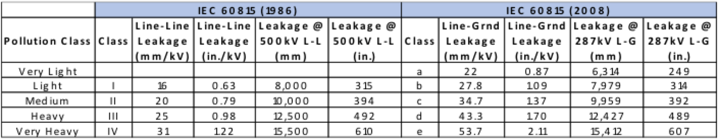

Once the correct ratio is determined for the applicable system voltage, a simple formula will find the target leakage distance that best defines proper choice of insulator. Significant improvements in insulator design over the years have allowed for various options to maximize leakage distance – from fog type ceramic bells to extra high leakage profiles on polymeric insulators. Nonetheless, independent of material, the role of leakage distance is to prolong the ability of an insulator to withstand the presence of surface contamination without resulting flashover between successive cleaning cycles, whether from rain or routine maintenance.
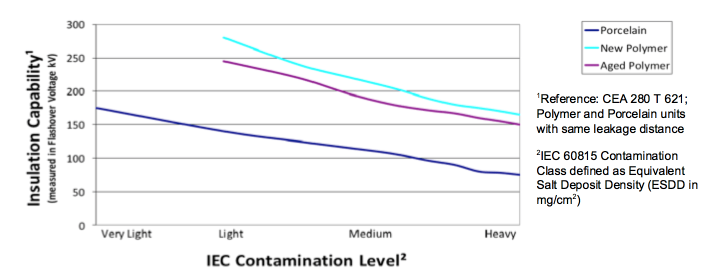
One effective means to verify the ability of an insulator to perform its function in a contaminated real-world environment is through a test of ESDD level combined with measuring flashover voltage. During such tests, insulators are exposed to varying levels of contamination while energized with voltage levels to induce flashover. Flashover is the phenomenon whereby voltage exceeds the insulating air gap across the insulator, which becomes compromised based on level of contamination present. It is of course important to avoid flashovers on transmission lines since auxiliary equipment such as breakers or re-closers can then be triggered and cause service interruptions.
For example, a flashover test comparing porcelain and polymeric insulators having similar electrical ratings and leakage distance revealed that porcelain (the dark blue line in Fig. 3) demonstrates relatively poor flashover performance across all voltages and contamination levels. By contrast, polymeric insulators, both new and aged, demonstrate superior flashover performance across all voltages and contamination levels due to inherent advantages of hydrophobicity and optimized geometry. Since hydrophobicity causes water to bead and prevents formation of a surface sheet of moisture, leakage currents are reduced. Hydrophobicity also aids in cleaning surfaces from contaminants since when water beads and runs off of a surface it removes loose contamination deposits. In this particular example, polymer insulators were tested as new and aged to allow for any possible decrease in hydrophobicity. But, as demonstrated, such decrease is minimal and superior performance versus porcelain is maintained. Silicone rubber insulators are therefore preferred in contaminated areas due to lower leakage currents combined with self-cleaning properties.

Environmental humidity levels have direct impact on power losses from transmission lines. As humidity level rises, leakage current increases relative to the length and resistance of the leakage path on insulator surfaces and to the rate at which moisture is supplied or removed. As stated above with regard to contamination performance, polymer insulators offer optimized geometry compared to porcelain bells by having smaller cores as well as a weathershed area that still meets leakage distance requirements. Such optimized geometry results in a higher leakage current density that in turn leads to the phenomenon of ohmic heating. This allows polymer insulators to dry faster than porcelain. In fact, laboratory testing has demonstrated that power losses for porcelain insulators are on the order of 10 times those measured for polymeric insulators.
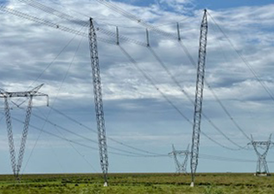
Another benefit of selecting polymeric insulators for transmission lines relates to transport requirements. Many projects are located in relatively inaccessible areas and increased public resistance to transmission towers is only pushing right-of-ways to even more remote areas. In addition, many projects span vast distances between generation and load centers. In such cases, traditional use of large equipment and extensive manpower may be neither feasible nor economical. When such challenges arise, polymer insulators offer distinct advantages due to reduced weight and packaging of complete insulators. Weighing more than 90% less than porcelain equivalents at 500 kV, the reduced weight and easier handling of polymer insulators provide a key advantage to minimize expense and environmental impact of construction.
Case Study for Optimized Transmission Line Design
High voltage transmission lines must be designed with focus on efficiency balanced with performance. The costs of the line will then justify whether or not it is a viable project. Such costs actually begin years before the line is constructed due to expense of design or land acquisition. Other costs persist over the entire life of a line to account for its operation and maintenance.
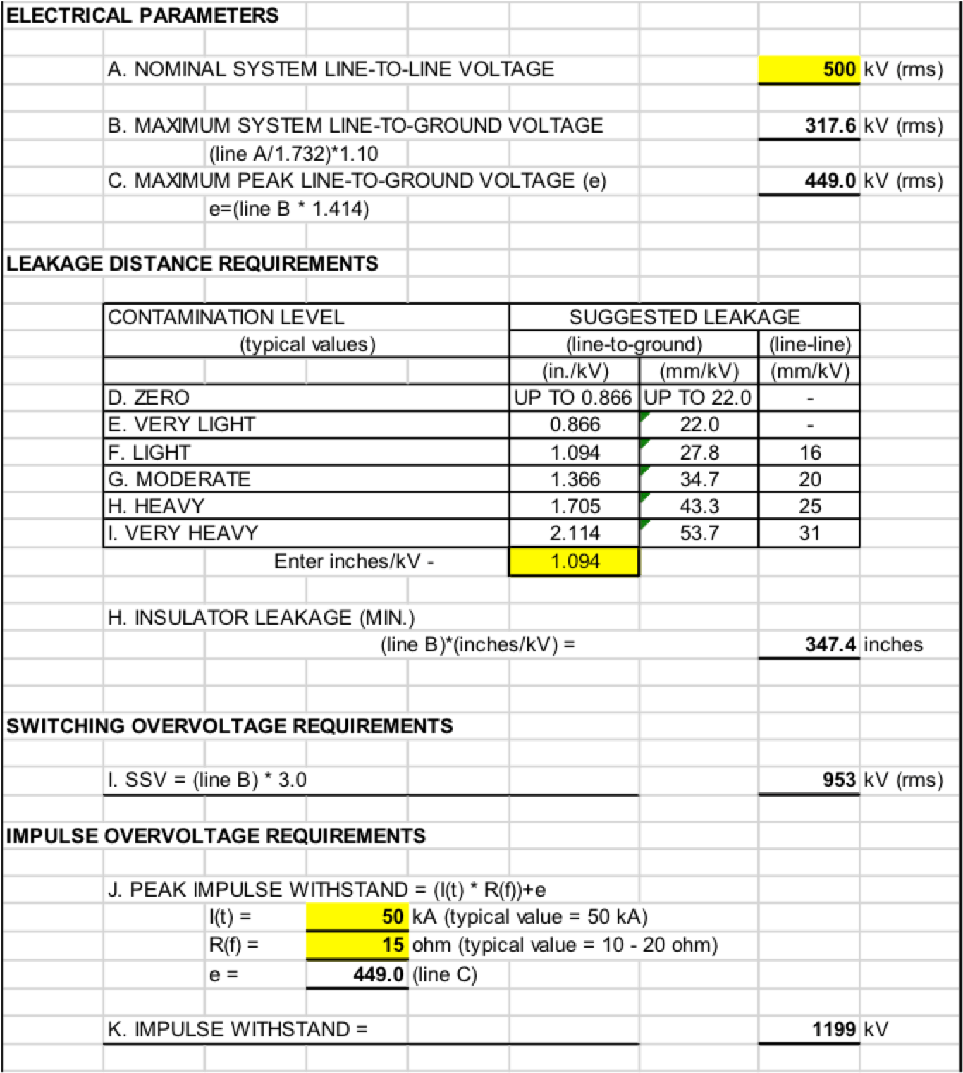
Extensive research exists that can assist optimization of conductor size and spacing or configurations that reduce power losses and minimize electric field phenomena. Below, a simple case study is explored with the assumption that certain tower and line design parameters have already been completed. Using the example of a 500 kV AC transmission project, a comparison is made of the impact of different choice of insulator material. The line in this case is in the United States and runs approximately 100 miles (160 km).
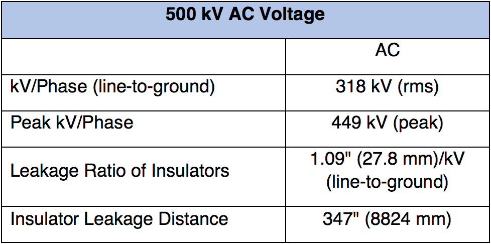
The service area was determined to be a light pollution environment and therefore applicable leakage ratio was defined per IEC 60815 and then related to system voltage to determine insulator leakage distance (see Table 2). In this way, pollution class that establishes creepage distance is usually one of the primary factors in proper insulator selection. Based on the criteria that have been presented for this line, specification of insulator characteristics can be developed and Table 3 shows the details applicable to proper selection of insulators for this project.

Insulator designs for the applicable data can now be established. Table 4 compares insulator selection and design for different material options based on type of assembly, i.e. tangent, angle or dead-end.
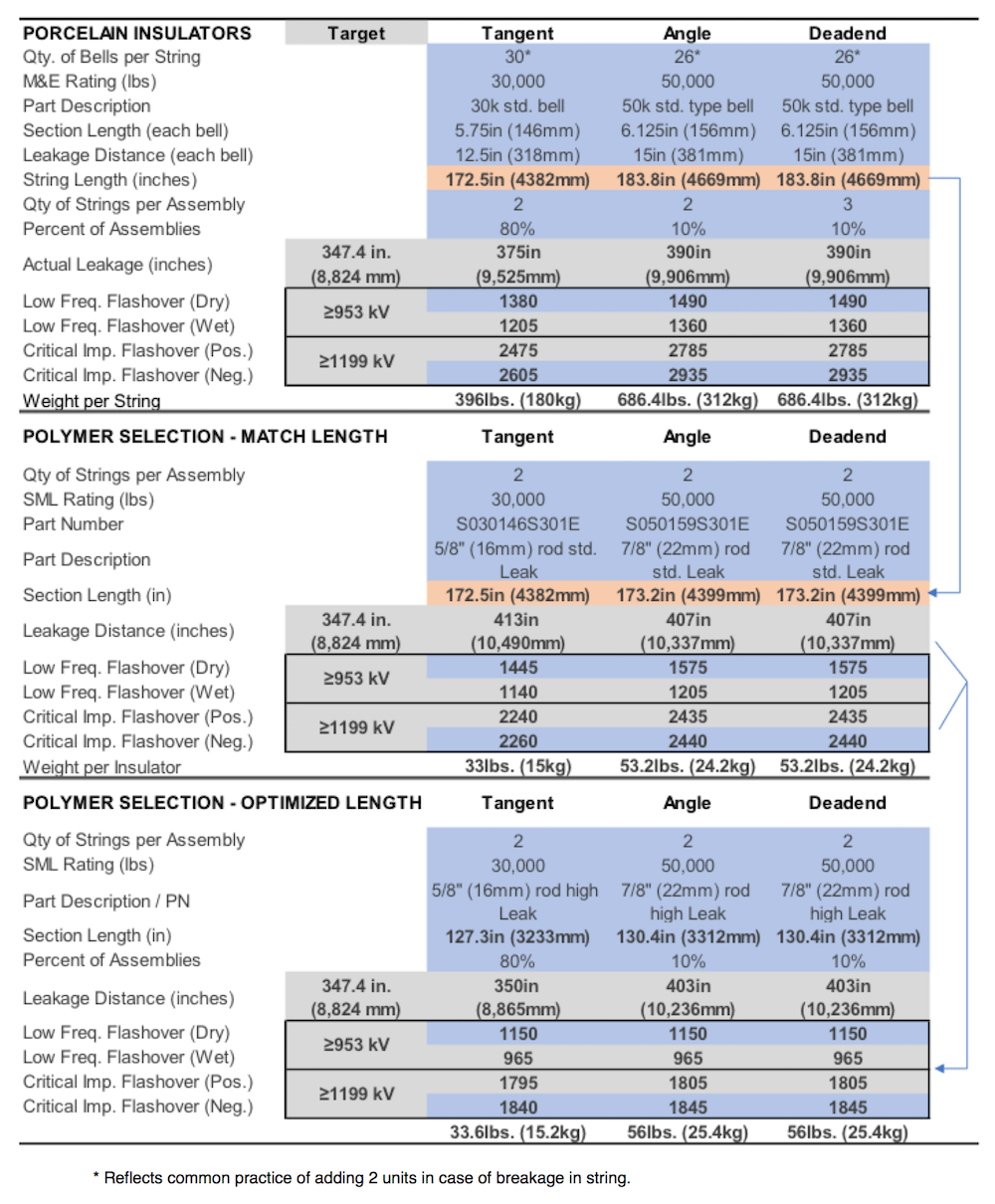
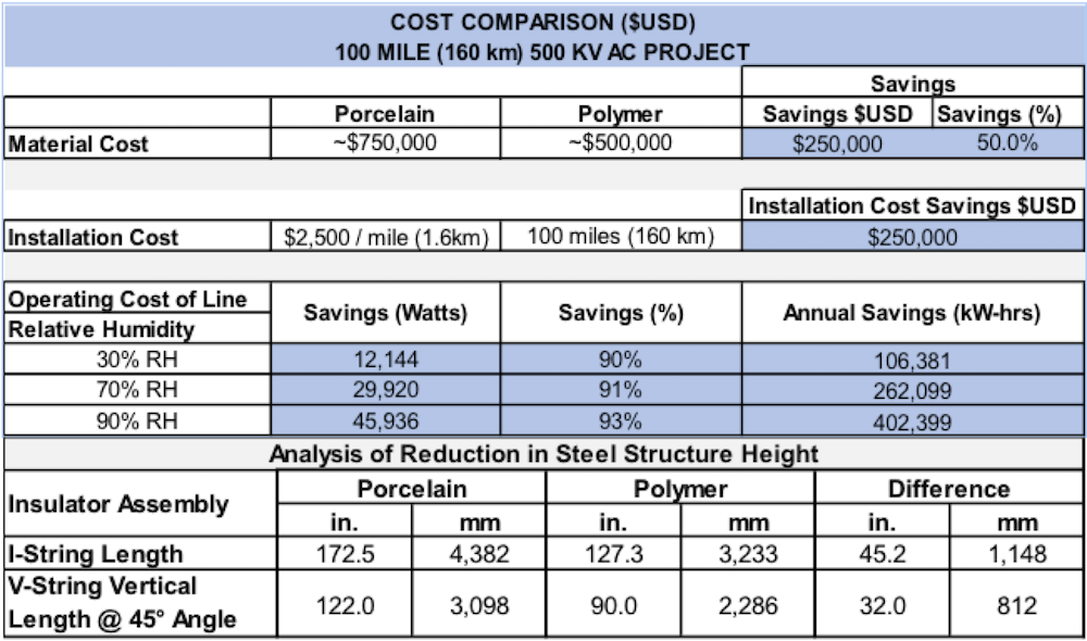
Table 5 compares relative costs based on selection of insulator for this 500 kV line. First of all, based on material selection, cost savings with polymer are alone over 50%. Secondly is comparative cost of installation. Due to efficiencies in packaging, weight, and installation of polymer insulators, one large contractor, for example, has quantified the savings realized as ~US$ 2500/mile, i.e. US$ 250K in the case of this particular project. A third level of cost comparison relates to impact of power losses on the system. As stated, all energized electrical equipment experiences some losses and these mean less generated power is reaching customers. Due to wide variation in power costs, monetary analysis is not provided here but it is nevertheless significant that polymer insulators can offer up to ~90% lower power losses compared to porcelain equivalents. A fourth level of cost savings relates to design of insulator assemblies and towers. Due to dramatic length differences for optimized designs, as shown in Table 4, as well as related weight differences, tower costs can be reduced and lead to significant additional savings along the entire length of the project. Clearly, overall cost of a transmission line is greatly impacted by selection of insulator material
.

Conclusions
There are many challenges to realize effective and efficient design for any high voltage transmission line. Thorough analysis must be made of impact of pollution, land availability and need for power delivery, coupled with environmental factors such as temperature, humidity and terrain challenges. Fortunately, more than 100 years of experience in transmission line design and construction combined with improved manufacturing processes, materials and testing are offering industry new options and methods. These options not only provide advantages in terms of cost savings but also offer decades of reliable performance. It is therefore important for key decision-makers and influencers to consider the impact that insulator selection decisions can have on optimizing transmission lines.
Bibliography
Bernstorf, R. A., & Ryan, D. (2007). Silicone Compounds for High-Voltage Insulators: Compounding Silicone Rubber. Aiken, SC: Hubbell Power Systems.
Bernstorf, R. A., & Ryan, D. (2007). Silicone Compounds for High-Voltage Insulators: HPS Silicone Testing. Aiken, SC: Hubbell Power Systems.
Ferguson, David (2006). Approaching zero discharge: in plant evaluation of zinc thermal diffusion cotaring technology, phase 1. Clean Techn Environ Policy (2006).
Goch, W. P., Bernstorf, R. A., & Elrod, J. W. (1986). Power Loss Comparisons in Porcelain and Polymer Suspension Insulators. Wadsworth, OH: The Ohio Brass Company – Hubbell Power Systems. Sept. 1986.
Hackam, R. (30 Sept. 1998). Outdoor High Voltage Polymeric Insulators. International Symposium on Electrical Insulating Materials.
International Electrotechnical Commission – IEC (1986) Publication 815: Guide for the selection of insulators in respect of polluted conditions.
International Electrotechnical Commission – IEC (2008) IEC 60815-2-2008: Selection and dimensioning of high-voltage insulators intended for use in polluted conditions.
National Electrical Manufacturers Association – NEMA (1984) NEMA HV2-1984: Suspension and Post Type Insulators for Electric Power Overhead Lines General Use Information.
Schwalm, Andy (2010). Insulators 101. IEEE/PES 2010 Transmission and Distribution Conference and Exposition. New Orleans, LA. April 2010