Transient overvoltages occur on all power systems. While arresters can be used to effectively control the most frequent type of such overvoltages, namely those caused by switching operations, transients due to lightning are more difficult to mitigate. How the insulation on any power system is protected is basically an economic issue. Clearly, it would not be reasonable to insulate only for the operating voltage and thereby allow any transients to trigger insulation failure. Similarly, it seems equally unreasonable to insulate for all transient events, even if this were possible. An intermediate solution that requires some reasonable investment in insulation and protective equipment is therefore the compromise most often taken. This carefully selected combination of insulators and arresters is then referred to as insulation coordination.
Insulation coordination is a well-developed engineering practice and one where the characteristics of the system in terms of insulation and arresters cross paths. The task of coordinating insulation withstand with the desired performance levels of the system can be significantly different if arresters are applied versus not applied. This coordination task as well as the task of selecting and locating arresters can be simple while at other times complex, requiring computer simulation. However, as a good first approximation, system performance can be modeled using the formulas presented in IEC 60071-1, 60071-2 and 60071-4. These standards cover 99% of what needs to be known to perform a lightning or switching surge insulation coordination study. IEEE 1313.1 and 1313.2 are another excellent source for better understanding this engineering practice while a third highly acclaimed reference is “Insulation Coordination of Power Systems” by Andrew Hileman (1999).
This edited past contribution by arrester expert, Jonathan Woodworth, reviewed fundamentals to help engineers decide whether a comprehensive study must be undertaken and what might be the benefits.

Insulation Characteristics
All insulation has limits to its withstand capability. Because it is not possible to insulate sufficiently to withstand all lightning surges, insulators are designed and tested to determine the levels at which they will flash over.
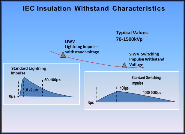
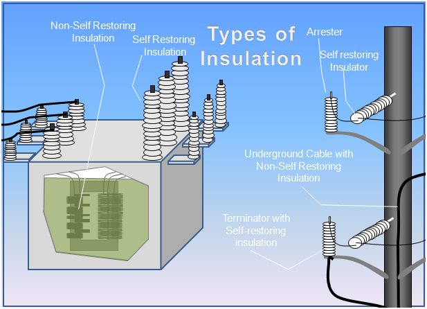

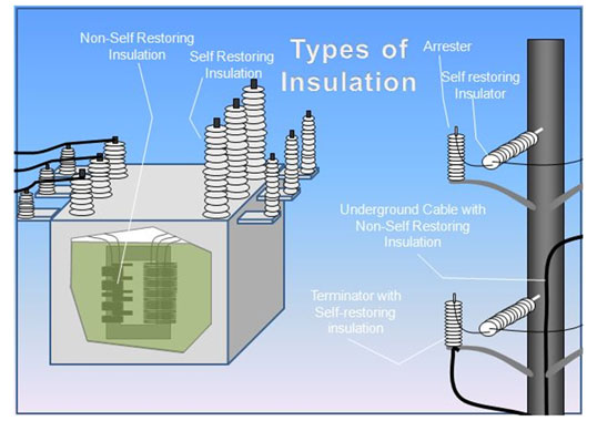
Insulation has two fundamental characteristics: lightning impulse withstand and switching impulse withstand, shown graphically in Fig. 1. The LIWV characteristics of external self-restoring insulation (see Fig. 2) are universally tested and verified under dry conditions. The actual direct length between the insulator terminals is the most significant factor in determining these fast impulse characteristics. The SIWV of external self-restoring insulation is universally tested under wet conditions because this withstand characteristic depends on an insulator’s creepage or leakage distance when wet (this being the total distance between the two terminals along the surface of all sheds).
Substation Insulation Coordination for Lightning Surges
Substations are subject to two types of overvoltages that can stress insulation. Even if a station is well shielded, lightning surges can enter indirectly. All stations connect to the rest of the system via incoming and outgoing overhead conductors. In the case of air-insulated substations, if lightning strikes these lines within the span of one or two towers from the substation, a surge is likely to enter the station along the conductors.
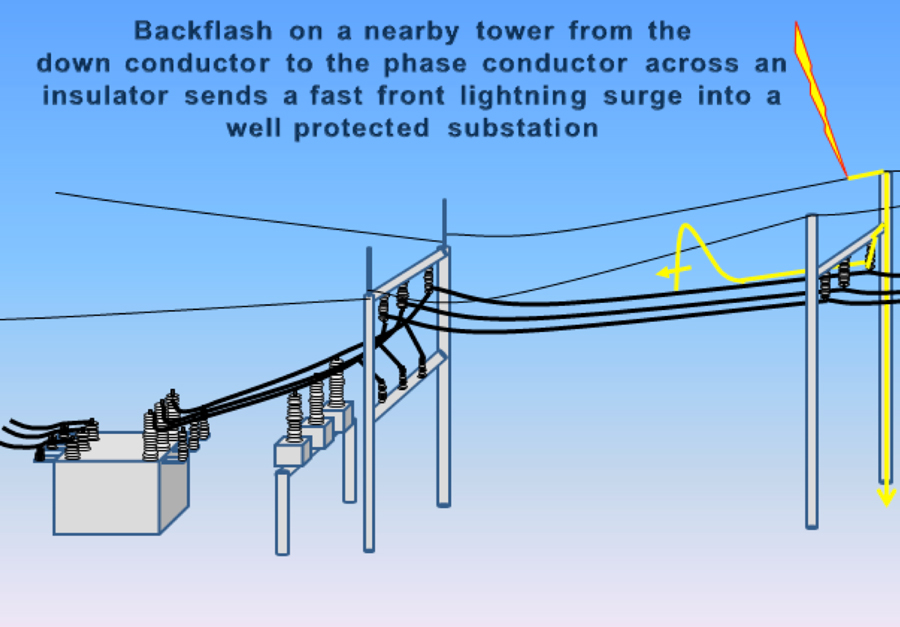
Even well shielded transmission lines can allow a fast rising surge to enter a nearby station if there is a backflash to the conductor during a switching or lightning surge (see Fig. 3). However, owing to the high insulation withstand on systems above 245 kV, such back-flashovers are much less probable then on systems below this voltage level. Moreover, they are rare on systems of 500 kV or higher.
Fast rising surges on an incoming conductor have a high probability of flashing over insulation in the station if there are no arresters. The amplitude of these incoming surges will be equal to the flashover level of the backflashed insulator. If the only mitigation tool is an arrester at the transformer, it will protect the transformer if properly coordinated with the transformer insulation. The arrester may even protect equipment on the surge side to some extent. In this type of coordination scenario, the probability of occurrence is quite low over the expected life of the transformer, which is probably 30-40 years. However, if a properly selected arrester is not located near the transformer, it only takes one such event to cause failure of a very expensive asset in the circuit.
Another important part of this coordination scenario is the state of the circuit breaker. If the breaker is in the open position, it will become an end point on the circuit. Because endpoints represent a significant change in impedance, voltage will be reflected and cause a doubling effect at the breaker. This voltage doubling effect (i.e. traveling wave theory) will likely cause the breaker insulator to flashover resulting in yet another path for current to flow to ground.
The voltage doubling effect can also occur if the breaker is open during operation to break the power frequency fault back at the tower. Since lightning seldom occurs as only a single stroke, another stroke along the original path can send a second fast rising surge down the same line. Due to these two potential open breaker scenarios, it is advisable to apply arresters at the line entrance of the station to eliminate the voltage doubling at the breaker and an almost certain flashover of its insulation.
Yet another variable to consider in substation coordination for lightning is the number of incoming lines to the station. Fortunately, more lines make it harder to flashover insulators at the substation but, at the same time, increase the likelihood of an incoming surge. Both factors are therefore used in the formulas used to determine proper coordination.

Separation Distance
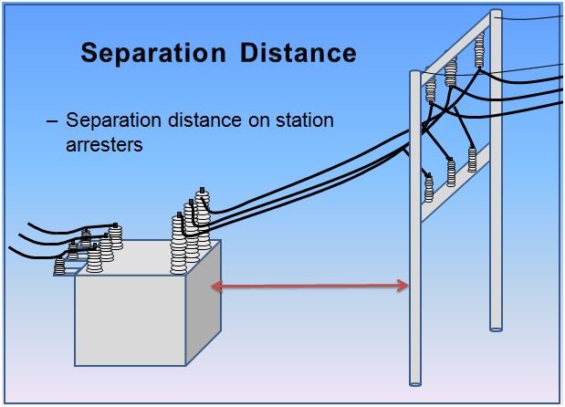
Separation distance is another important consideration when it comes to protection of substations and their insulation coordination. Arresters will limit or clamp a fast rising surge according to their own UI characteristics immediately in their vicinity. However, as protected insulation is located further from the arrester, it is increasingly less protected from fast rising surges as described above. (Note: There are no separation distance issues for slow rising surges from switching sources.)
This reduced protection is again due to the effects of traveling waves and reflections. For this reason, the location of and distance between critical insulation points in the substation need to be known before a proper insulation coordination study can be completed. Of course, the non-self restoring insulation of the transformer is generally of highest consideration when it comes to separation distance issues. The formula for determining the farthest possible distance between an arrester and the transformer it protects is found in the above references as well as in IEC 60099-5. The higher the system voltage, the shorter the separation distance becomes because the ratio of transformer withstand voltage to system voltage is reduced.

Substation Insulation Coordination for Switching Surges
Switching surges are of concern only on systems of 245 kV and above since their magnitudes for systems below that level generally do not exceed 1.5 pu of the system phase-to-ground voltage. This is due to the fact that line capacitance, length and voltage are not high enough to result in challenging surges.
There are numerous sources of slow front switching surges at substations and circuit breakers or switching devices are involved in all forms of such surges. Fault and fault clearing overvoltages are generated in the unfaulted phase when the fault is first initiated and when the voltage is re-established.
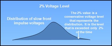
Switching surge statistical level, known as the 2% voltage (see Fig. 5), range from 1-2 per unit of the crest phase-to-ground voltage if they are mitigated with pre-insertion resistors or arresters. However, if they are not mitigated, their levels can easily exceed 2.0 pu. When energization and re-energization surges are mitigated, load rejection surges need attention. Switching inductive and capacitive currents need particular attention when the associated breakers experience pre-strike or restrike. In this case the range of 2% voltages is 2 – 2.5 pu.
There are two methods used in the practice of insulation coordination for this scenario. The deterministic method is used exclusively when applied to non self-restoring insulation. When coordinating self-restoring insulation, statistical (also known as probabilistic) methods are almost universally used. The basic difference between these methods is that in the deterministic method absolute maximum and minimum values are coordinated. For example, the maximum residual voltage of an arrester for a slow front surge is coordinated and compared to the minimum withstand level of transformer switching impulse. When using the statistical method in determining the flashover rate of the 25 self-restoring post insulators in the substation, the probability of flashover occurrence and magnitude of the surge are used in the calculation. The results are a probability distribution representing the overall switching surge flashover rate.
Arrester Characteristics & Substation Insulation Coordination
Arresters are a fundamental part of insulation coordination in the substation. They are used universally to protect the non self-restoring insulation of power transformers. As stated above, the coordination of non-self restoring insulation is accomplished using the deterministic method. This is because there are no acceptable test methods that can determine the probability of disruptive discharge in oil/paper insulation systems. Therefore the only option is to accept a deterministic approach.
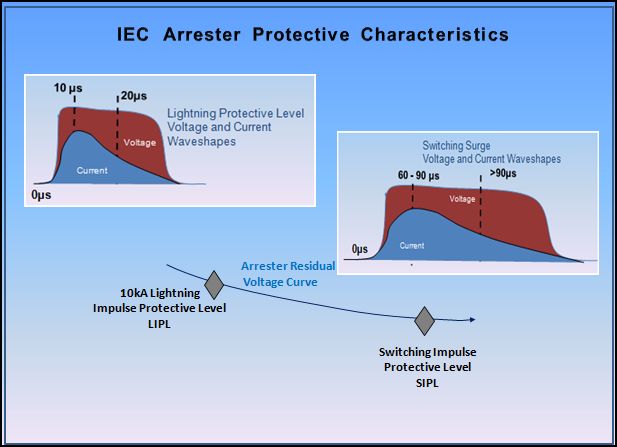
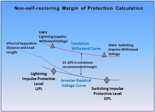
Arresters applied in substations characterized by three voltages relative to insulation coordination; the arrester operating voltage (Uc), the lightning impulse protective level (LIPL) and the switching impulse protective level (SIPL). These are shown in Fig. 6. For non self-restoring insulation, a deterministic comparison is undertaken. After the insulation and arrester characteristics are determined, they are coordinated to ensure there is ample safety margin between them. The comparative graph is shown in Fig. 7 and referred to as the Margin of Protection.
Environmental Effects on Insulation Coordination
Flashover voltages for air gaps depend on the moisture content and density of air. Insulation strength increases with absolute humidity up to the point where condensation forms on the insulator surfaces. Because insulation strength decreases with decreasing air density, longer strike distance is required to attain the same flashover voltage at 2000m elevation then at 100m above sea level. A detailed description of the effects of air density and absolute humidity are given in IEC 60-1 for different types of voltage stresses. When determining the co-ordination withstand voltage, it should be kept in mind that most adverse conditions from the strength point of view (i.e. low absolute humidity, low air pressure and high temperature) do not usually occur simultaneously. In addition, at any given site the corrections applicable for humidity and ambient temperature variations basically cancel each other. Therefore, the estimation of strength can usually be based on the average ambient conditions at the location.
When contamination from salt or industrial pollution is present, the response of external insulation to power-frequency voltages becomes important and may dictate longer creepage or leakage distances. This type of contamination does not adversely affect lightning and fast front withstand levels. Flashover of insulation generally occurs when the surface is contaminated and becomes wet due to light rain, snow, dew or fog without any significant accompanying washing effect.

Transmission Line Insulation Coordination
Transmission line insulation coordination is also separated into two categories: lightning and switching. The performance assessment methods are based on expected lightning and switching overvoltages and their corresponding insulation levels. Since line insulation is self-recovering, their performances are usually determined by the statistical method. The basic practices outlined in substation insulation coordination also apply to line coordination.
The sum of the back flashover rate (BFR) and shielding failure rate (SFR) determine the flashover rate (FOR), expressed in flashovers/100km/year. The back flashover rate is the most significant cause of outages on transmission lines. While the fast-rising surge associated with a backflash seldom makes it to the substation due to corona effects, the resulting fault current and breaker operation is felt over the entire length of the system. Oftentimes, a switching surge is experienced immediately following any lightning induced flashover.
Another significant variable usually involved in lightning flashover coordination is the system elevation. The CFO of a line insulator can be reduced by as much as 20% at higher elevations and, since transmission lines often traverse high elevations, this factor must be considered. For higher elevations, insulators might need to be lengthened or arresters applied. Both are excellent means of mitigation.
Switching impulse studies need only be considered for lines exceeding 245 kV. For lines below this level, switching surge magnitudes generally do not overstress normal insulation configurations but, for levels above 245 kV, the stresses can be significant.
The switching surge flashover rate (SSFOR) is determined by numerical integration of the Stress-Strength relationship. The stress in this case is the switching impulse voltage or switching overvoltage (SOV) quantified by a probability distribution. Strength is the switching impulse withstand voltage (CFO). IEC 60071-2 defines this process in detail. If arresters are used to mitigate the SSFOR, the evaluation method is modified to accommodate the change in the SOV since it will no longer be a normal distribution but instead a truncated distribution.

Distribution Systems Insulation Coordination
The practice of distribution system insulation coordination is limited. Still, there are a number of specific deterministic practices that are quite important. The margin of protection calculations for some system configurations can determine when and when not to use arresters. For example, on underground circuits where voltage doubling is common, a margin of protection calculation can reveal that applying an arrester only at the riser pole for systems above 25 kV can be essential. When this is the case, then open point arresters are recommended to provide a lower risk of cable failure.
On delta distribution systems, a close check of the margin of protection can often show that there is little margin compared to well-grounded systems. This is due to the fact that higher rated arresters are applied to these circuits to give them ample overvoltage withstand capability. By raising the operating voltage of the arrester, the clamping voltage is also increased and the margin between the transformer’s withstand curve and the arrester’s clamping curve is decreased.
Another factor that can have a major impact on insulation coordination on distribution systems is the lead lengths on arresters. Long leads can effectively render an arrester unable to protect non self-restoring insulation on distribution equipment.
Conclusions
While a number of variables can be involved in the engineering of insulation coordination and which can make this task quite complex, optimization of application of arresters can result in significant savings on insulation cost for all types of systems.