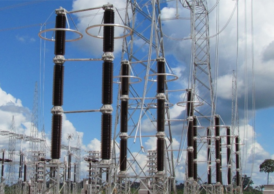
Several years ago, a HV cable termination operating in a Mediterranean country experienced catastrophic failure, scattering high velocity porcelain shards in all directions. The installation was next to a parking lot but fortunately the failure occurred when it was mostly empty. Otherwise, the event might have proven much more than a repair job for maintenance crews and become a public relations problem for the power company. While cases such as this are rare, they are not isolated and serve as constant reminders of the explosion risks whenever electrical arcing occurs inside a porcelain-housed component filled with oil or pressurized gas. There are potential risks for polymeric-housed components as well, although of a different nature.
This edited past INMR article, contributed by experts at CESI in Italy, addressed major safety issues that impact test programs for components such as HV cable terminations, surge arresters and bushings.

Safety & Risk Assessment at Substations
These days, transmission system operators (TSOs) in many countries are searching for solutions to meet growing demand for electrical power. The only realistic option will be more HV, EHV and UHV AC and DC systems – which means growing populations of cable terminations, bushings and arresters placed into service. Stringent international regulations are also pushing utilities to rely on testing as one of the most effective means to demonstrate that they are working with due diligence whenever specifying such equipment. This requirement becomes all the more important if one considers the growing numbers of substations and electrical installations located near population centers as well as the accompanying push to reduce substation ‘footprints’. Both trends represent increased risk factors in terms of danger to public safety as well as the economic consequences of collateral damage should there be a catastrophic failure. It is therefore increasingly important to look for possible upgrades in technology while also decreasing failures at the early stages of service life. The latter can only be achieved through more detailed installation practices in which all critical functions are well defined and where greater attention is paid to the skills required of the workers involved.
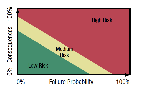
According to ISO/IEC Guide 51 safety is “freedom from unacceptable risk”. This can be achieved by reducing risk to some tolerable level that takes into account that there will always be some amount of residual risk, i.e. the risk that remains even after all possible protective measures have been undertaken. This risk is then determined by arriving at some optimal balance between the ideal of absolute safety and the demands met by the product, which includes benefits to the user, suitability for purpose and cost effectiveness. Safety criteria must be considered first in order to be able to specify the required safety level and to perform the related risk assessment. One way to do this is to combine all the technical as well as non-technical (e.g. social and economic) parameters that play a role so as to evaluate failure probability and its consequences. The final risk can then be estimated using the so-called Whitman (Farmer) diagram, shown in Fig. 1. For example, to reduce residual risk and also to lower the cost of the consequences, explosion-free cable terminations and bushings are increasingly being specified.
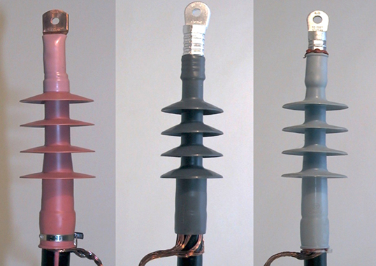
HV Cable Terminations
Table 1, taken from a CIGRE Technical Brochure, illustrates rates and consequences of failures of cables and accessories in relation to overhead lines. Here, the major consequence looked at is measured by repair time.
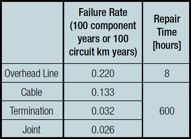
Table 1: Typical Failure Rates for 380 kV XLPE Cable Systems & 380 kV Overhead Line Values per System (3 phases)*
At the same time, if a termination that is about to fail happens to be filled with oil, the oil can ignite or be spilled into the environment. In certain cases, a resulting explosion can also damage adjoining apparatus, which means even longer repair times and higher costs – quite apart from the risk of personal injury to whoever happens to be nearby at time of failure. Indeed, one of the compelling reasons to specify explosion-free terminations at the transition from overhead lines to cables is to avoid dispersal of debris from any explosion resulting from overpressure due to internal short circuit.

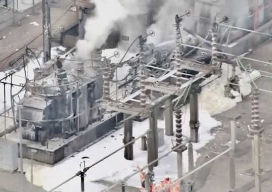
Bushings
Failures of bushings are responsible for a significant proportion of all transformer failures and can also be extremely violent. Although often regarded as only accessories, the fact is that bushings are the single major cause (roughly 80%) of all failures and fires involving transformers filled with insulating mineral oil (even though fire actually occurs in less than 15% of all transformer failures). Failures of bushings can result in the porcelain housing shattering into shards and other fragments that are projected at high velocities over a wide area. Oil sprayed into the surroundings through the cracked unit can also become ignited by the arc associated with the fault. In extreme cases, fireballs some five times higher than the transformer itself have been observed following the explosive failure of a bushing.
Physical protection against explosions and fires involving HV bushings in service are often difficult or even impossible to put in place due to the size and location of the equipment. Whenever a particular type of bushing is regarded as being at unacceptably high risk of such failure, access to the site should be limited, during which time design changes to improve safety can be discussed with the manufacturer. Because of the considerations discussed above, explosion-free designs of HV bushings – still seen as a comparatively new technology – are increasingly being used to obtain lower risk solutions in applications where substations are located in urban areas with buildings in the vicinity. While testing of explosive behavior may not yet be mandatory, it is increasingly being conducted these days in order to enhance reliability and reduce risk, irrespective of location of the installation.
Surge Arresters
HV metal oxide arresters are generally considered extremely reliable components with very low failure rates. Still, proper selection of a unit’s ratings and characteristics with respect to the electrical, mechanical and environmental stresses is crucial to maintaining this low failure probability.
The risk of failure can therefore never be completely disregarded, especially in places where attention to quality is not overly stringent or where type testing is not universally applied. Potential reasons for surge arrester failure include: severe energy stresses related to temporary overvoltage phenomena or lightning and switching events; moisture ingress; and ageing of internal parts. With respect to short circuit performance, two different surge arrester designs have to be considered:
Type A: Designs with internal gas volume
These arresters are either porcelain or polymer-housed with a tube design. Design A type surge arresters are fitted with pressure relief devices at both ends intended to vent any internal overpressure and to transfer the arc to the outside.
Type B: Designs without internal gas volume
These surge arresters are polymer-housed, with either a ‘wrapped’ or ‘cage’ design. In the case of Design B type arresters, any gas generated internally will be expelled directly through the housing. This can take place through a ‘weak point’ intentionally placed there for this purpose (for the wrapped design) or through the space between loops (for the cage design).
Potential risk factors in the case of arrester failures can involve three aspects:
1. In the case of violent shattering, there is the possibility of ejection of housing fragments, resistor blocks or metal fittings and connections. Here, porcelain-housed designs present a greater risk simply because porcelain fragments are inherently more dangerous than soft polymeric fragments.
2. There is the possibility that arrester failure ignites a fire near the installation site. In this case, the risk for a polymer-housed design is greater since the polymeric material and FRP structure can potentially both catch fire. For porcelain designs, the only parts that can ignite are the sulfur cement and O-rings.
3. Possible detachment of the connection between the arrester and the power circuit. This is linked to the risk that connections, which are melted by the burning arc and pulled off by electro-dynamic forces, are projected toward and damage neighboring apparatus. Arrester failure can then evolve into a multi-phase short circuit. In order to avoid this, the top cap and connection must be properly designed to withstand short circuit currents.

Procedures for Internal Arc Testing
Testing and certification are important tools to ensure both the safety and reliability of electrical networks. For the reasons discussed above, among the HV components most often submitted to testing for safety reasons are cable terminations, arresters and bushings. The main difference when it comes to testing these components lies in the applicable situation in respect to the norms. While IEC and IEEE standards already exist for arresters, there are still no international standards available for HV bushings and cable terminations. Rather, technical specifications for these have been prepared by major national utilities, such as Terna, EdF/RTE, etc. while European standards (HD) are also available.
The HD standard, for example, prescribes triggering the internal arc in a termination by drilling a hole in the main insulation. A 1.5 mm2 copper wire then connects to the screen/metal sheath or a piece of metal is connected to the shield/sheath in order to simulate failure. Later, a short circuit current is applied, whose values (kA and seconds) are chosen according to the maximum short circuit current of the circuit where the HV termination is to be installed. In spite of the fact that the scope of this standard is limited to cables and accessories up to 170 kV, the same test modalities are also now being used for higher ratings of terminations as well as for bushings. Based on experience gained from such tests over past years, it can be stated that an internal arc test on HV terminations and bushings is usually demanding for both the laboratory and the manufacturer involved, since:
• test set-up and auxiliary electrical facilities such as power source connections, etc. need to be expressly installed and then dismantled after the test;
• demanding protection measures have to be put in place to avoid environmental problems;
• ejected parts from violent shattering can damage the test chamber and even the nearby surroundings;
• smoke and noise are harmful to test staff and the environment, which, taken together with the high test ratings, may require overnight tests.
These challenges will only become greater in the future if one considers the increasing market demand for higher values of short circuit current.
As for surge arresters, the ‘classical’ IEC pressure relief test procedure initially developed for gapped silicon carbide porcelain-housed types and then extended to cover metal oxide porcelain-housed designs was found not to be suitable to cover the polymer-housed arresters developed since the 1990s.
A significant revision of testing technique and procedure as well as of the relevant standard itself was therefore necessary to address the problem. This activity was undertaken by TC37 MT4 and the task took several years.
One of the challenges was finding a compromise between the need to represent actual service phenomena as faithfully as possible and the technical limitations as well as costs at existing high power laboratories.
Also, a major change had to be introduced for Design B type arresters in the short circuit preparation phase, i.e. replacing the classical shorting wire placed all along the resistor column by an electrical pre-failing procedure better able to simulate actual service phenomenon. The relevant standard – IEC 60099-4 am1 – was published in May 2006.
One of the problems that had to be faced by laboratories when testing Design A type arresters at rated short circuit current is their increasingly significant high arc resistance as they become longer. This issue, together with reduction of available test voltage due to the high symmetrical current required, can lead to a major reduction of the asymmetry factor achieved during testing. To overcome this, a three-phase test setup has been introduced. A delayed operation for making the third phase significantly increases prospective asymmetry factor and enables the required testing performance to be achieved. In regard to testing Design B type arresters, the critical issue is the pre-failing process. Here, the resistor blocks have to be electrically pre-failed such that during the following test phase the power arc can be established when energized at test voltage by the power supply. A proper selection of suitable pre-failing test circuits and procedures is crucial to allowing testing of surge arresters with both high rated voltage and high rated current. In fact, for such surge arresters the available test voltage of the power supply is a small percentage of the rated voltage of the unit under test.

Short circuit testing of HV arresters can also be quite demanding for any high power laboratory, for much the same reasons discussed above for terminations. These types of issues will only become more relevant as testing involves bigger and bigger units with increasing test currents. Based on experience gained testing arresters on behalf of several different manufacturers according to the latest IEC standard as well as other applicable national or international standards, the following conclusions can be drawn:
1. Compared to other type tests prescribed for arresters, the short circuit test remains the critical one since the percentage of failing results is considerably higher than for the other tests;
2. Testing at rated current is usually far more important in regard to risk of violent shattering versus testing at reduced or low currents;
3. For polymer-housed arresters, testing at low current is the more critical in regard to the risk of fire ignition;
4. Detachment of the connection between the arrester and the power circuit is a potential problem area, however is still not being adequately considered within the evaluation criteria of present international standards.
Conclusions
Worldwide demand for power networks will only increase, pushing utilities to install growing populations of HV cable terminations, bushings and surge arresters. At the same time, attention to safety and the environment are also growing. Proper selection of the ratings and characteristics of these components together with high quality levels will be key to reducing the probability of failures even though risk of such events can never be completely disregarded. Therefore, laboratory tests to simulate internal fault will remain a useful tool to help select those products that have safe performance during failure and reduce risk of violent explosion or fire on the network. Requirements for safety of substation equipment will only become more stringent. As such, it will also become more important to harmonize and standardize testing requests coming from utilities across the globe.