Among the important trends in the electricity supply industry is growing emphasis on safety as well as reducing risks associated with explosive failure of components, especially those that contain flammable materials. In this regard, dry type cable accessories offer clear environmental and safety benefits compared to conventional outdoor cable terminations that employ insulating oil. The challenge, however, has been that any new dry insulating material to replace oil needs to offer not only high dielectric strength but also good thermal conductivity since convective thermal dissipation is lost when a liquid is replaced by dry insulation.
This edited contribution to INMR by Andrea Nassi and Guoyan Sun of Brugg Cables reviews progress developing and testing a new dry insulating material for application on outdoor cable terminations as well as for other HV apparatus.


The common oil-insulated outdoor cable termination used in interconnection between overhead and underground power transmission networks consists mainly of:
1. an insulator made of porcelain or a polymeric housing moulded over a GFRP tube;
2. a stress cone; and
3. an insulating fluid that fills the void between stress cone and inner walls of the insulator.
An insulating fluid is suitable for both low and high voltage applications since these offer generally good dielectric performance. Dissipation of thermal losses due to cable current and dielectric losses (which are proportional to the cable conductor voltage) are achieved mainly by convection and conduction. Such a design is easy to produce at relatively low cost and is suitable for all voltage levels.
Nonetheless, dry type cable accessories provide certain advantages, mainly from the environmental and safety points of view. Apart from eliminating fluid insulation media and their related expansion mechanisms, dry type solutions also offer benefits such as easier and faster installation, thereby significantly reducing outage time in cases of replacement.
Given this, cable accessory manufacturers have worked to develop concepts for a fully dry outdoor termination. Still, physical limits have been encountered at the highest voltage levels and it has proven difficult to test a universal design that is not only scalable but that can also be offered at a competitive price. Generally, development and market introduction of any HV equipment based on new technologies and concepts is rather slow. Users in the conservative power supply industry generally most trust technologies that have a 30 to 40 year track record of functionality and reliability.
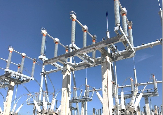
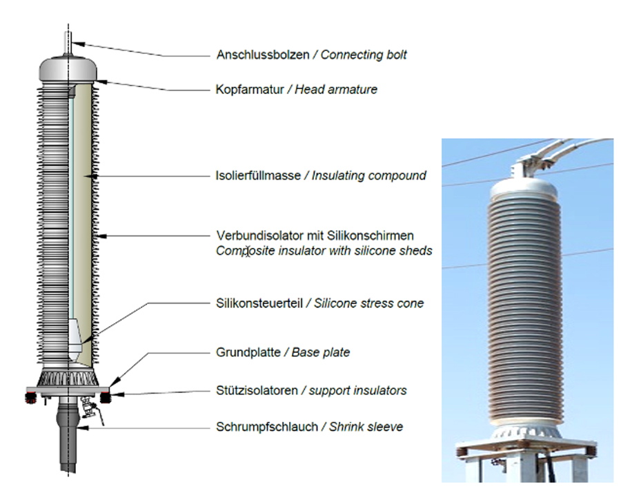
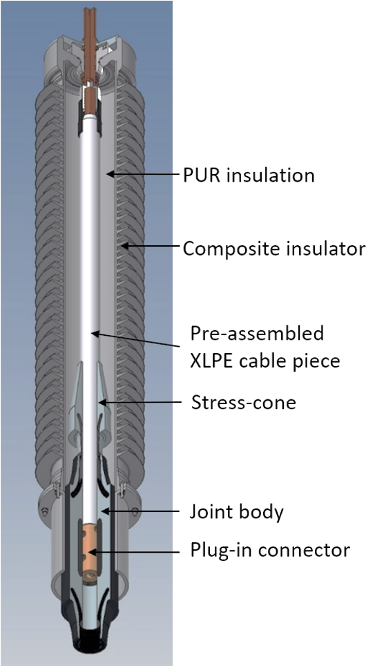
Standard cable terminations (as shown in Fig. 1) with a stress cone use geometrical field grading that makes them bulkier with relatively wide body diameters. New designs for outdoor cable termination have aimed to replace the insulating fluid with a dry or gel type insulating medium. This has worked well, especially for voltages up to Umax of 170 kV. But from Umax of 245 kV and higher, depending on design, field control techniques, materials and volumes, physical limits are reached when it comes to direct replacement of the insulating fluid due mainly to thermal runaway.
Certain commercial and technical aspects need to be considered when developing any new HV apparatus:
• Product requirements and market needs;
• Electrical and mechanical aspects, including dielectric materials, type/prequalification tests, ampacity, seismic characteristics;
• Unknown long-term behaviour of new materials;
• Cost;
• Existing competitive designs (patents issued and granted);
• Customer acceptance.
Additional market requirements in the case of cable terminations include:
• easy on-site assembly;
• protection & security of personnel;
• low life cycle cost;
• ease of monitoring.

Methods to Control Electric Field
Selecting a suitable method for grading electric field is perhaps the most critical step when designing any new high voltage equipment. First of all, it must keep local field enhancement within design rules as well as the dielectric strength limits of the insulating medium being used. Secondly, it will have an impact on geometry and size of the equipment and materials being used. The former will determine apparatus quality; the latter will affect overall development and production costs and thus market competitiveness.
There are different field grading methods and materials, depending on system type (AC or DC) and voltage level. The two principal methods can be differentiated based on whether capacitive or resistive current dominates the field grading mechanism:
1. Capacitive field grading, which can be geometric electrode grading, capacitive field grading with conductive elements in the insulation (condenser body) and refractive grading with high-permittivity materials;
2. Resistive field control, which uses materials where electric field depends on their resistivity and permittivity characteristics.
Resistive field control has not yet been substantially developed and successfully implemented in high voltage applications. This is due to high permanent conductive thermal losses and associated complex electric field and frequency dependent resistivity and permittivity. Broadened use will therefore require further research and development with comparatively slow integration, especially at these voltage levels.

New Dry Type Outdoor Cable Termination Combining Conventional Termination with Cable Joint Body
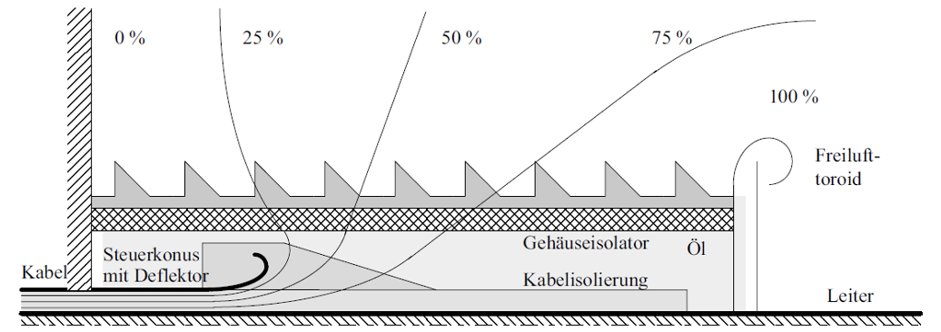
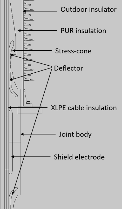
Since polymeric cables such as XLPE use geometric field control, it is easier to keep the field control between conductor and cable screen using a deflector, as shown in Figs. 1 & 2. (Note: Older oil insulated cable terminations for oil cables use capacitive grading partly by winding conductive foils between the paper insulation and then impregnating with oil).
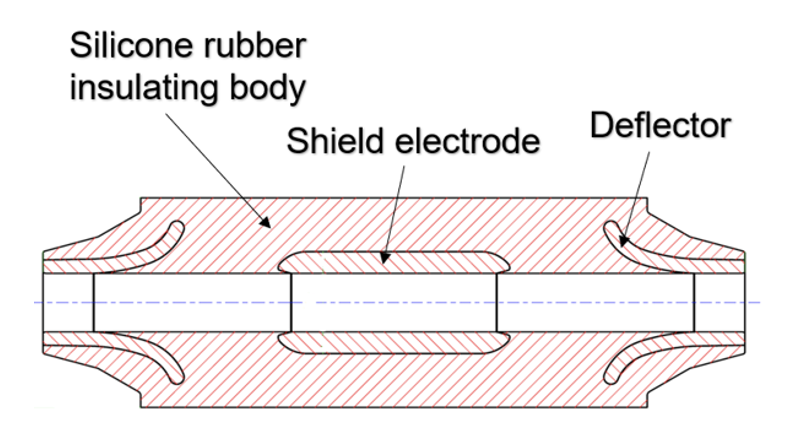
The same field control principle is used in a cable joint that consists of a middle deflector (shield electrode) at high potential and 2 grounding deflectors. Electric field is then concentrated between the middle deflector and the side ground deflectors (see Fig. 3).
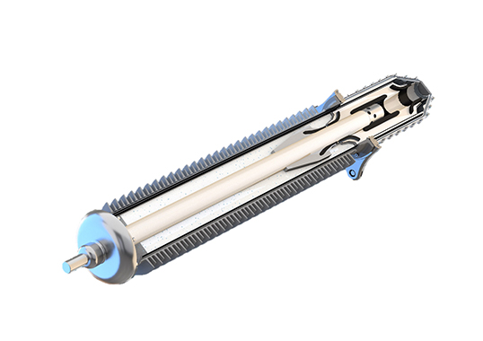
The newly developed dry cable termination combines a conventional termination with a single stress-cone and a joint body on the lower side, which creates the same interface for the cable entry as a cable joint. The empty bulk space within the outdoor insulator is then filled with a dry insulating compound in place of insulating oil (see Fig. 4).
The intersection point of the stress cone of an oil-filled outdoor sealing end and a joint is the deflector, which is at the same potential as the cable sheath. Both are at ground potential. Joining them gives the possibility to insert a cable into a geometric field control and then shield its conductor by the HV shield electrode.
The basic approach in this new dry type design is to factory cast the space between the XLPE cable and the inner tube of the insulator with a dry insulating compound. This design offers the possibility of a plug-in dry type design for the cable connection. A protection box/casing is applied over the silicone body following insertion of the cable and serves to protect the termination against the environment, including water, humidity and dirt. At the same time, this allows for thermal or mechanical expansion of the silicone parts of the termination in both axial and radial directions.

Results of Simulation
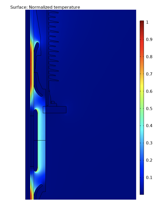
To verify the new concept, FEM simulations of electric field distribution were first performed based on a standard Umax 170 kV cable joint and 170 kV outdoor cable termination. Figs. 5 & 6 show the 2D model of the axial symmetric cut of the critical parts of this dry type termination, i.e. the joint body, stress-cone and HV cable.
Dimensions and design were kept the same as existing state-of-the-art components that have proven long-term functionality and quality. Results showed no higher electric fields than typical for standard cable joints. Electric field was normed to the Emax, which in this case is within the cable insulation (see Fig. 6).
Development of Insulating Compound
The new material to be developed using this concept was the insulating compound, which is filled and cured in the factory. Following are the main specifications established before starting material development and testing:
• high dielectric strength;
• good thermal conductivity;
• low production costs.
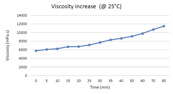
Achieving sufficiently good thermal conductivity is crucial since thermal dissipation by convection, given in any liquid insulating material, is lost when replaced by a dry insulation. The compound developed is a 2-component polyurethane-based resin with a hardening time of about 24 h. Fig. 7 shows its change in viscosity over time and there is sufficient time for optimal casting in the factory and relatively short curing of 24 h.
The following key material characteristics were achieved:
• initial viscosity: 5000 – 6000 mPas;
• pot-life (@25°C): 80 min;
• gel time: 8 -10 h;
• hardening time: 24 – 48 h;
• relative permeability Ɛr (@50 Hz): 3.7 (IEC 250);
• dielectric strength (50 HZ, sample thickness 2mm): 20-24 kV/mm (IEC 243);
• thermal conductivity: 0.25 W/m*K (ISO 117).
This ‘PUR’ insulating compound is filled in the factory and the cable termination delivered to the site as a plug-in termination. The interface for the cable is the connector within the joint body and a sliding contact was developed for this. One part is pre-assembled in the factory and placed within the shield electrode of the termination’s lower part. The second part is assembled on-site on the prepared XLPE cable and its conductor. The termination is slid onto the cable using silicone grease.

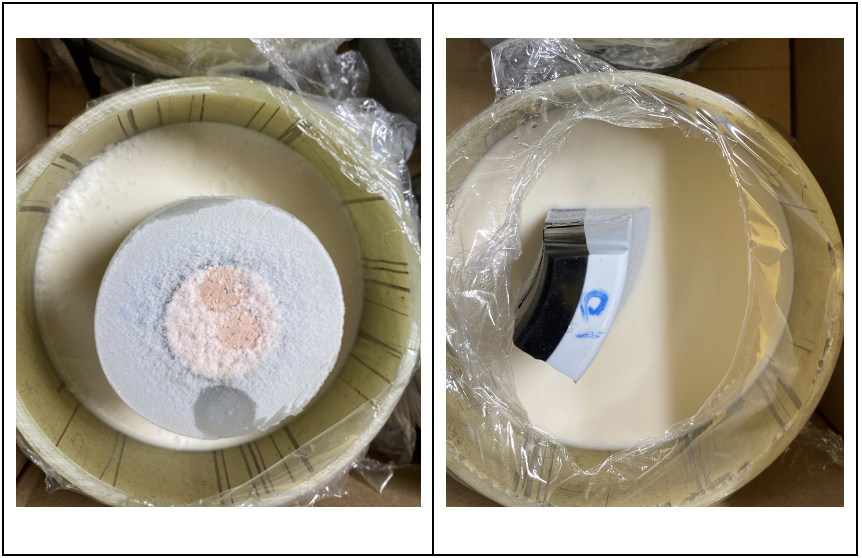
Investigating Interface During Cold Start of Termination
In a cold start scenario, sufficient adhesion between the XLPE-PUR insulation, silicone-PUR insulation and GFRP-PUR insulation interfaces must be provided. To test for this, small geometry samples were cooled to -80°C and their adhesive properties optically tested. The samples had the same adhesive behaviour as a sample at room temperature and at temperatures up to 90°C (see Fig. 8). After the cold samples were heated, their adhesive properties remained the same. This important property of the PUR insulating compound allows the dry type termination to be installed at sites where cold starts are probable.
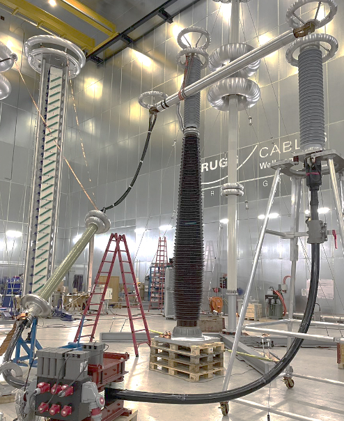
Type Test According to IEC 60840
The termination passed the type-test requirements according to IEC 60840 for 170 kV system voltage, including 20 heating cycles (see Fig. 9).
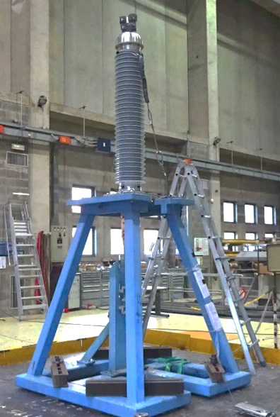
A seismic test was also passed successfully according to a customer specific test specification based mainly on IEEE 693-2018, with 1g horizontal and 0.8g vertical ZPA.
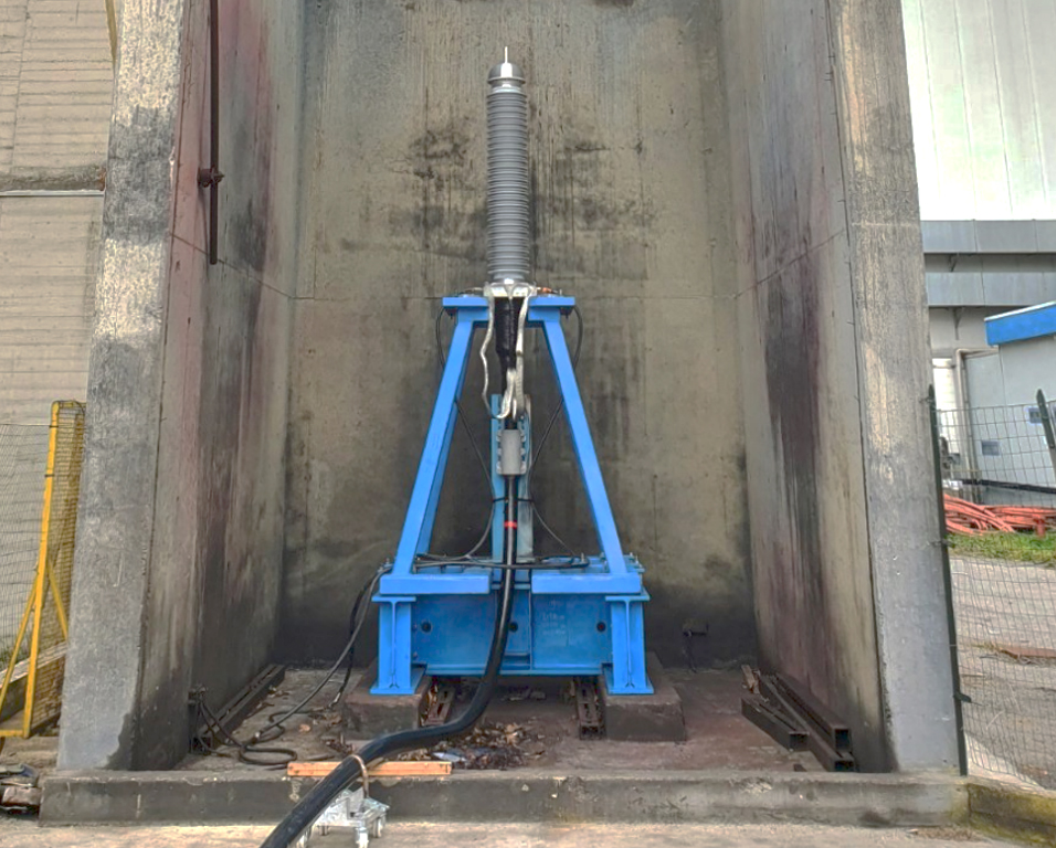
Explosion-Proof Dry Outdoor Termination
An internal arcing test was performed with the condition that no parts of the damaged termination are allowed outside a radius of 3 m from the centre of the termination. The short circuit current was 31.5 kA with a duration of 0.5 s. The test passed successfully. The test object remained on the original position. No solid debris belonging to the termination were found more than 3 meters away from the termination (see Fig. 11).
Outlook
The next steps in developing new cable terminations based on this concept will be:
• environmental long-term ageing testing (2000 h), including salt fog testing at elevated phase-to-earth voltage;
• extending the product range down to 72 kV system voltage;
• type-testing according to the IEEE Standard (for the U.S.);
• exploring the thermal limits of this insulating medium, i.e. -> testing a 245 kV dry type termination.
References
[1] A. Küchler, 2005, Hochspannungstechnik: Grundlagen – Technologie – Anwendungen, Springer Berlin Heidelberg, Berlin, Germany, 427-440
[2] F. H. Kreuger, 1991, Industrial High Voltage, vol. I. Delft University Press, Delft, the Netherlands, 151–165
[3] T. Christen, L. Donzel und F. Greuter, 2010, “Nonlinear Resistive Electric Field Grading Part 1: Theory and Simulation”, IEEE Electrical Insulation Magazine, Vol. 26, No. 6, 47–59
[4] T. Christen, L. Donzel und F. Greuter, 2011, “Nonlinear Resistive Electric Field Grading Part 2: Materials and Applications”, IEEE Electrical Insulation Magazine, Vol. 27, No. 2, 18–29.
[5] X. Qi, Z. Zheng, and S. Boggs, 2004, “Engineering with nonlinear dielectrics,” IEEE Electrical Insulation Magazine, vol. 20, No. 6, pp. 27–34, 2004.
[6] J. Debus, 2015, Untersuchungen der Anwendungsmöglichkeiten mikrovaristorgefüllter Feldsteuerelemente in der elektrischen Energietechnik, Darmstadt-DE
[7] K. Oono, S. Kaneko, I. Takaoka, 2007, “Development Of Dry Type Outdoor Termination for 66 – 110KV XLPE Cable”, Jicable ’07