Metal oxide surge arresters have very high reliability. MOSAs can function almost indefinitely, assuming they have been well designed, properly manufactured and operated within their specified range of applied voltage, temporary overvoltage, surge magnitude and surge energy. It is of course also important that they are not damaged due to some external physical force. Nonetheless, arresters do occasionally fail in service, implying that one or more of these factors have been violated. ‘Failure’ usually means that the arrester has suffered an internal short circuit, placing a fault (most often line-to-ground) on the system. Almost invariably, this fault results in operation of a circuit-interrupting device, whether circuit breaker, recloser or fuse, causing disruption of service. If the arrester is equipped with a disconnector, as are most distribution arresters in the U.S., the disconnector should operate when the fault current flows following an arrester short circuit, thereby isolating it either from the ground or from the line, depending on where the disconnector is installed. Then, upon re-energization, the failed arrester is no longer in the circuit electrically and service can be continued, albeit with reduced level of surge protection.
In the case of a station arrester, failure will typically cause a system lockout until either that portion of the substation can be by-passed or until the arrester is removed from service. While it is desirable to avoid arrester failures at all times, the consequence of a station arrester failure is typically far more severe than for a distribution arrester. Generally, a considerably greater disruption of service accompanies failure of a station arrester. Moreover, the cost of replacing a station arrester is orders of magnitude higher than for a distribution arrester.
This edited 2015 contribution to INMR by Steve Brewer of Hubbell Power Systems explains why these devices must be monitored as well as the most effective ways this can be accomplished.

Goals of Field Testing
The primary reasons why field-testing programs are undertaken by end users include:
1. Determining if the arrester is near end-of-life;
2. Predicting when end-of-life will occur; and
3. Evaluating if the arrester is still providing protection to the insulation it is protecting.
The first two objectives can reasonably be achieved while the third goal is often not practical in a field environment. Fortunately, with today’s MOV arresters and the design tests they must pass there is virtually no duty that can impact an arresters ability to protect.
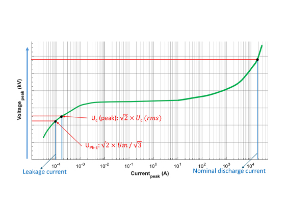
In order to better understand end-of-life testing, it is important to have knowledge of how the surge arrester behaves under power frequency conditions not only when the arrester has aged but also when it is tested in the factory prior to shipment. Under normal line-to-ground power frequency voltages, surge arrester current is nearly all capacitive. The chart below shows relationship between the voltage and current on a new surge arrester:
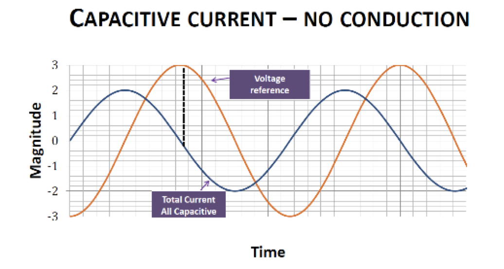
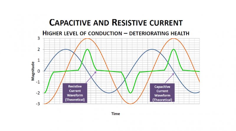
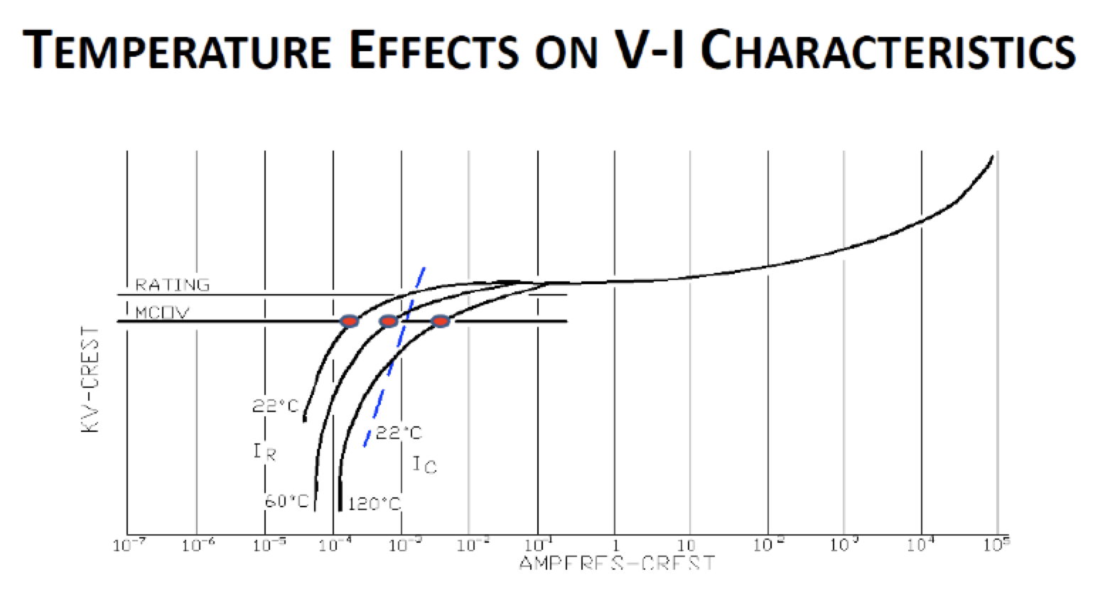
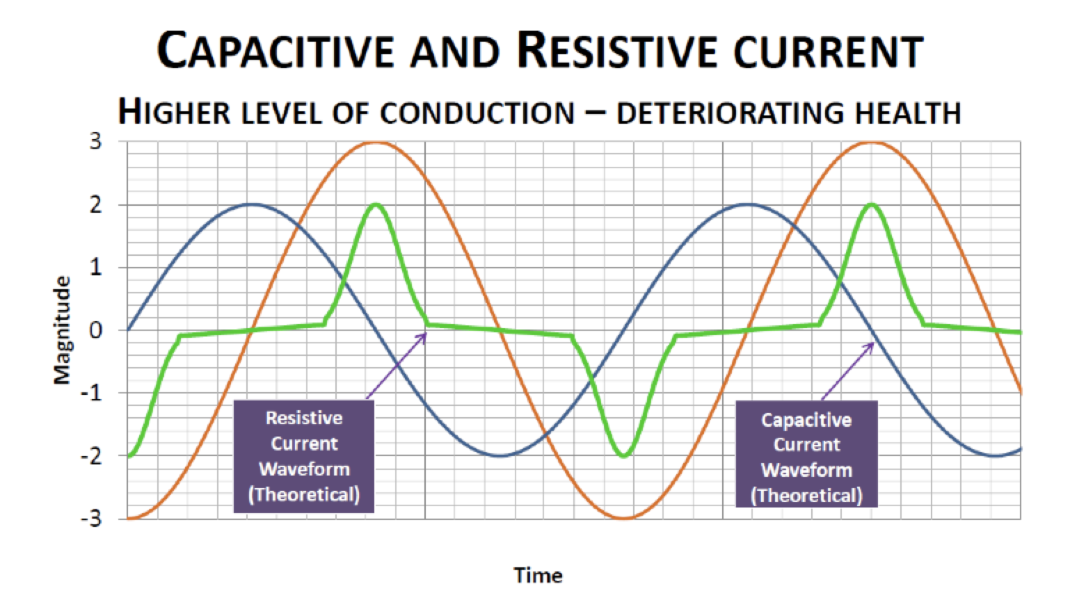
As voltage on the arrester increases, the current waveform becomes much more resistive in nature. This characteristic is also true if the voltage remains constant but the internal temperature of the arrester increases for some reason. Monitoring the resistive component of current over time is going to be key in all efforts to evaluate the internal state of the arrester and to predict its ultimate demise. MOV blocks exhibit a negative temperature coefficient and, as such, the resistive component of current will increase as block temperature increases. The two following charts demonstrate these characteristics.
 Failure Modes
Almost without exception, failure of an arrester results in a complete short-circuiting of the arrester inside its external housing. It is possible that an arrester could flashover externally without its external air gap being compromised (e.g. by animal, bird or vegetation). But, typically, the MOV blocks prevent the terminal-to-terminal voltage reaching the point, under any circumstance, where such external flashover could occur. Under almost all scenarios, failure ultimately occurs as a result of dielectric breakdown. The internal structure of the arrester has deteriorated to the point that it is no longer able to withstand the voltage applied to its terminal whether this be normal system voltage, a temporary power frequency overvoltage (e.g. following external line faults or switching) or lightning or switching surge overvoltages. The ways an arrester could reach such a state are varied, although occurrence is rare:
1. Moisture Ingress
Perhaps the most common root cause of arrester failure is moisture ingress to the interior, implying that it was not well designed and/or not properly manufactured and/or physically damaged by some external force that compromised its sealing system.
2. Temporary Overvoltage (TOV)
Under normal operating conditions, i.e. arrester energized at its maximum continuous operating voltage (MCOV), the temperature of the MOV blocks rises just slightly above ambient to the point where the heat being generated by the blocks is perfectly matched by the heat the arrester dissipates into surrounding air. If the power frequency voltage across the arrester increases (e.g. as a result of a system disturbance, fault or switching operation), the MOV blocks conduct more current and begin to rise in temperature. If the overvoltage is of sufficient magnitude, the heat generated by the MOV blocks will always be greater than can be dissipated and a potential thermal runaway situation will be generated.
3. Ageing of MOV Blocks
In the early days of MOSAs, MOV blocks usually exhibited an ageing characteristic whereby their power dissipation at a given voltage slowly but continuously increased over time. The effect on arrester performance of this behavior would be similar to that described above for TOV, in that, after some time in service, the power (heat) generated by the blocks would be similar to that resulting from a TOV when the blocks were new. At some later time, the heat generated would be equivalent to that generated by a higher TOV when the blocks were new. Ultimately, the heat generated could reach a point where no stable operating point could be maintained. Fortunately, with significant improvement in processing technology over the past 35 years, high quality MOV blocks produced today exhibit a characteristic whereby power dissipation actually decreases over time at any given voltage. This implies that they become more rather than less thermally stable over time and therefore unlikely to cause arrester failure through block ageing.
4. Thermal Runaway Resulting from Surge Duty
Surge duty referred to here is that resulting from relatively high current surges due to lightning, switching of long lines or capacitor banks. Some of these surges may have very high amplitudes but relatively short duration (e.g. lightning surges) while others may have much longer duration but with significantly lower amplitude (e.g. switching surges). All have a certain charge content that, when passed through the arrester result in a certain amount of energy absorbed by the blocks. This absorbed energy results in almost immediate heating (i.e. adiabatic) of the blocks. If the input of energy is too high, the temperature rise of the blocks may be such that the arrester is pushed into a thermal runaway condition.
5. Damage to MOV Blocks Resulting from Surge Duty
One manifestation of energy absorbed by MOV blocks is rise in temperature of the blocks, as described above. However, if the energy is of a sufficiently high magnitude and is deposited into the blocks in a sufficiently short timeframe, the blocks may become physically and irreversibly damaged. The thermo-mechanical shock imparted to the blocks can cause the blocks to crack into two or more pieces. In some cases, a block may be punctured in a localized area, either partially or completely through its body. In other cases, a pinhole type failure may occur at the edge of the block, sometimes causing material to be removed from the outside peripheral surface. Typically, each form of physical damage is accompanied by degradation of the electrical integrity of the block, either in its inability to sustain another energy event without complete electrical breakdown or reduction in its ability to support normal operating voltage. Both could sooner or later result in complete arrester failure.
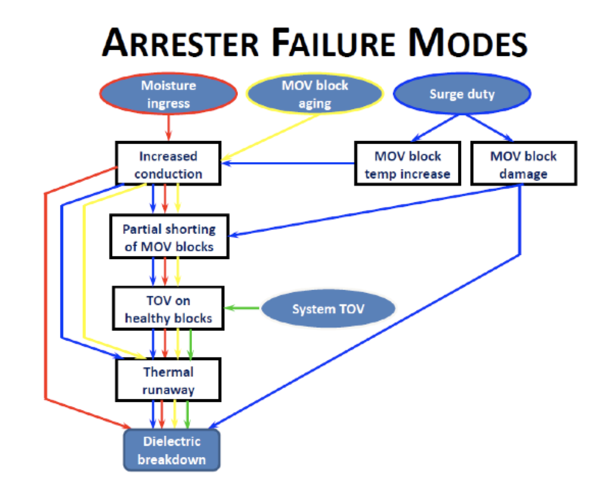
The chart below displays typical failure modes for MOV surge arresters in flow charge format. In all cases, the final failure mode will be increased conduction ultimately leading to complete dielectric breakdown. Therefore, it is clear that measuring temperature and/or resistive component of current is key to monitoring internal condition of a surge arrester.
 On-Line Monitoring Methods
Utilities generally prefer on-line measurement methods that do not require a substation to be taken out of service. For all methods discussed below, it is important that a baseline measurement be established and data taken over time to look for trends indicating an increase in resistive current. As far as what measurements are acceptable, this value may vary among different manufacturers. The supplier of the particular arrester being evaluated should ideally be contacted for their input on appropriate limits.

1. Infrared Imaging
Increases in power losses that occur in a degrading arrester will result in an increase in temperature of the MOV blocks in the arrester or at least in part of the arrester. Unfortunately, MOV block temperature is not a characteristic that can be directly measured in a conventionally constructed arrester. Many utilities use indirect means, e.g. infrared thermography. Heat generated by the MOV blocks inside an arrester is dissipated to the outside by conduction, radiation or convection. For sufficiently high generation of heat, the outside surface of the arrester housing can be elevated above ambient temperature. The heated surface emits radiation that can be detected by an infrared sensor, allowing an estimate of surface temperature. The device used for such detection could be an infrared thermometer that merely registers temperature of the spot or small area on which the device is focused. Alternatively, an infrared camera can be used that captures a thermal image over a wider area, thereby providing a temperature profile over the entire length or a major section of the arrester. This non-contact method of measurement clearly has appeal since it can be conducted from safe distance and can be performed quickly and at practically any time.
However, this technique is not without potential for error and needs careful interpretation. The amount of radiation emitted from a heated surface depends on its emissivity. A shiny surface with low emissivity will emit less radiation at a given temperature than a dull surface with high emissivity at that same temperature. The ‘apparent’ temperature registered by the infrared device could therefore be different although the actual temperature is the same in both cases. Other problems can occur with reflected radiation from nearby sources or from the sun. While such problems are not insurmountable, they do need to be taken into account. It is always advisable that individuals taking the measurements have received proper training in taking and interpreting infrared thermographic measurements.
Even with ‘accurate’ measurements of arrester temperature, it is not always easy to determine their significance. As for off-line techniques, there is no single hard-and-fast threshold that delineates a ‘good’ arrester from a ‘bad’ arrester. Again, judgment needs to be employed. Without knowing details about the thermal properties of the arrester ‘package’, it is not straightforward to translate temperature measured on the outside of the housing to temperature of the internal MOV blocks. Different types of arrester design and construction will differ in this regard. Because an arrester has some region that appears hotter is not necessarily an indication of an existing or emerging problem. Particularly on high voltage, multi-unit arresters, it is likely that temperature near the top will be higher than at lower points. This is because there is inevitably some degree of non-linearity in voltage distribution along the column of MOV blocks – even with grading rings employed). Blocks near the top are typically stressed above the average for the entire arrester and consequently likely to be running somewhat hotter than the overall arrester average.
Manufacturers typically advise taking thermal profiles of arresters on all three phase at a particular location over a short span of time to avoid issues with changing ambient conditions and to look for differences between these profiles. There is low probability that a degradation problem exists in all three arresters and of even lower probability that degradation is progressing at exactly the same rate in all. If relatively modest variation in temperature along the arrester (e.g. less than 5-10°C) exists but is the same for all arresters, one can be assured that there is no issue with these arresters. The key is examining for significant differences between arresters, e.g. one having a distinctly different temperature profile versus the others. Even then, this does not necessarily mean that the arrester in question is ‘bad’ but rather suggests that the arresters should be monitored more regularly to see if differences increase.
2. Resistive Component of Current
While it is impractical to monitor arrester power losses in the field and MOV block temperature cannot be measured directly, one parameter that can be monitored directly and continuously is arrester current. Such measurement requires that the arrester be isolated from ground by placing it on an insulating sub-base and then connecting the isolated base of the arrester to ground via a conductive path that bridges the sub-base.
A device connected in this conductive path can be used to obtain a signal that is proportional to arrester current. This device could be a resistive shunt of several hundred to a few thousand ohms (e.g. a 1 kΩ shunt would provide a 2 volt signal for an arrester current of 2 mA). Alternatively, an appropriately sized current transformer could be placed around the conductor (e.g. a current transformer with a 1:100 turns ratio and a 10 kΩ burden would provide a 200 mV signal for an arrester current of 2 mA). In either case, protection needs to be provided, such as in the form of a small MOV across the terminals of the measuring device This will limit output voltages if and when the arrester is called upon to limit surge overvoltages, which could result in short duration impulse currents of many kA.

Most manufacturers offer devices for measuring arrester current. These widely used and relatively simple devices provide a measurement of the total current flowing through an arrester, typically in terms of peak magnitude or peak/√2 (i.e. to provide a quasi-rms value).
The above suggests that monitoring the resistive component of current would provide a better indication of arrester health than monitoring total current. This is true but, unfortunately, while total current can be directly and easily measured on in-service arresters, it is difficult to extract the resistive component. As indicated earlier, the peak of the resistive component occurs at the instant of the peak of the voltage across the arrester. If accurate information regarding voltage waveform were available, it would become possible to determine the value of the total current at the instant of voltage peak, thereby yielding the peak value of the resistive component. While possible in a controlled laboratory setting, this is almost impossible to do in the field. Obtaining an accurate measure of the waveform of the voltage applied to any specific arrester being monitored would require an expensive and extremely accurate voltage divider with zero phase-angle error.
3. 3rd Harmonic Measurements
If an arrester, at normal operating voltage, conducts increasing amounts of current because of degradation of its volt-amp characteristic, the resistive component of the arrester current is a far more sensitive measure of degradation than is total current. This is because total current is dominated by the significant capacitive component until the arrester has degraded substantially. However, the resistive component is not readily extractable from the total current, especially in the case of in-service field measurements. Simulation and experimental data demonstrate that the 3rd harmonic component of arrester current provides a reasonable indirect means of estimating the resistive component and can therefore serve as a means to monitor degree of degradation of an arrester’s conducting properties. In the field, measurement of the 3rd harmonic component of current can easily be undertaken on energized arresters and instruments are commercially available for this purpose. When considering a 3rd harmonic monitoring system, an important factor to take into account is system frequency. A device designed for a 60 Hz system will not function properly on a 50 Hz system.
4. Absolute Temperature
The best monitoring method would appear to be direct measurement of internal block temperature since this would be the most direct reflection of a change in the resistive component of current. Surge arresters with built in thermal monitoring devices do not require use of insulating sub-bases and would not be as susceptible to the impact of external leakage currents. Unfortunately, given current arrester technology, this monitoring method is not yet practical.
5. Power Loss at MCOV
For practically all possible underlying causes of degradation of an arrester’s performance, the resistive component of current will increase over time. With steady applied voltage to an arrester, this results in an increase in its power losses. However, measurement of power loss of an arrester in service is not easy to accomplish. This requires separate measurements of the voltage applied to the arrester and of the arrester current, these quantities then being multiplied and integrated over time. For accurate determination of power loss, there must be no phase shift errors in voltage and current measurements. In other words, the signal that represents the applied voltage must be exactly 90 degrees out of phase with the capacitive component of the signal that represents the current. Even small phase errors can result in large percentage errors in power loss measurement. Moreover, measurement of voltage requires an expensive piece of equipment such as a high voltage divider or potential transformer. For these reasons, measurement of power losses on assembled arresters at normal operating voltage is still something done mainly in a high voltage laboratory or in a manufacturer’s factory.

Practical Issues & Conclusions
One common question is how often an arrester should be evaluated. Since rate of deterioration of a surge arrester, if any, can vary greatly, it is recommended that testing be performed as often as possible given budgets and other constraints. It is also important to maintain records over time and compare current information with baseline data.
It is possible to damage an MOV arrester from an overvoltage and this can happen accidentally in the course of field-testing. For example, high potential testing is not recommended for MOV surge arresters due to risk of resulting damage. Finally, to ensure that only internal arrester currents are measured, it is important to be sure the surface of the arrester is clean and dry.