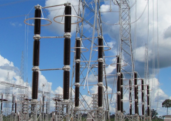
As surge protective devices, arresters mitigate the impact of events that might otherwise trigger outages, Monitoring them has therefore become part of an industry-wide trend toward greater condition assessment of key network components. Over most of its service life, an arrester behaves much like an insulator, with low leakage current over its insulating surface and very low levels through the internal zinc oxide disks. (Maintaining such low leakage current is required to ensure that the arrester will live up to its normal 20 to 40 year life expectancy.) In fact, the only time an arrester does not behave like an insulator is when it is failing or clamping a surge.
A number of assessment methods and indicators have traditionally been utilized to reveal signs of deterioration and provide clues to impending arrester failure. These range from fault indicators and disconnectors (which indicate complete failure) to instruments that can measure small changes in the resistive leakage current or power loss in the case of gapless type metal-oxide arresters.
This INMR article from a decade ago, contributed by arrester expert Jonathan Woodworth, offered guidance on these methods, whether thermal, electrical or mechanical. It also provided information about leakage current measurement of metal-oxide arresters as well as ways to evaluate an arrester when it is off-line or in the test laboratory. Here, the term ‘arrester condition monitoring’ is generally considered to be on-line and continuous while ‘arrester field-testing’ is off-line and carried out periodically over the arrester’s service life.

Asset management is a fast growing field in today’s ‘leaner’ utility environment and one of its most popular methodologies is the use of condition-based maintenance programs. This type of asset management does not rely on a specific maintenance schedule but rather one that is condition-based and therefore more cost-efficient. However, for such a maintenance program to work in practice, assets must be constantly monitored. Determining the condition of an arrester asset is still a developing field and several methods are currently available. Still, condition assessment comes with a cost and is therefore most often performed only at critical locations on the network where failure could have serious ramifications (i.e. an outage and loss of revenue). The goal in such cases is to predict imminent failure and have the arrester removed before it does indeed fail. Arrester field-testing is another form of asset management and most often carried out to determine if an arrester can be safely reinstalled.

Types of Monitors
1. Surge Counters
Such devices basically count impulses at currents above certain amplitudes or above some combination of amplitude and duration. If the interval between discharges is very short (e.g. less than 50 ms), such counters may not register each current impulse and this is often the case during multi-stroke flash events. Some counters require power follow current, as is generally present through silicon carbide arresters, and might not count the short impulse currents through metal-oxide arresters. Depending on operating principle and sensitivity, a counter will provide some indication of overvoltage events appearing on the system. It can also give information on the number of discharges corresponding to significant energy stresses on the arrester.
It is important to note that electro-mechanical surge counters alone do not offer any specific information about the condition of an MOV type arrester other than to register the surges it has encountered above a certain amplitude. Still, knowing a surge has taken place on the system is sometimes very useful and in this case a surge counter can be valuable. However, again, since only those surges of high magnitude or long duration can degrade an MOV type arrester, knowing the number of surges alone does not necessarily correlate with the arrester’s relative ‘health’. Indeed, this type of arrester is designed to withstand thousands of surges as long as these are within its normal operating capability. Therefore, repetitive surges should not in themselves lead to degradation.
Installation Considerations
For a surge counter to operate properly, the arrester must be isolated from earth by insulators at the base and the counter electrically mounted in series. The surge counter should ideally be located where it can be read from ground level with the arrester in service and installation should be done without significantly lengthening the earth connection or reducing its cross-section. It is important to note that the insulators used should be selected so that the specified cantilever strength of the arrester is not reduced.
2. AC Leakage Current Meters
AAC leakage meters are generally an accessory for surge counters. When the readout is an analog meter, the current being displayed is the total current of the arrester. The arrester’s total leakage current is then a combination of the capacitive current and the resistive current through the disks and over its external housing. If the arrester is equipped with a special ground terminal that isolates the internal from external currents, then only total internal current is monitored without interference from external surface leakage current. Another advantage of this arrangement (shown in Fig. 3) is that no insulators are needed at the bottom if monitoring surface leakage current is of no interest. For very tall arresters or those located in a seismic region, this could prove a big advantage.
Because metal oxide disks are more like insulators than conductors during steady state, they conduct very little resistive current but can carry from 2 to 10 ma of capacitive current. However, such a high level of current offers no useful data about the actual condition of an arrester. If an arrester is failing, the current shown on the leakage current meter may not even change. Unfortunately, a 5 ma or higher total current (99% being capacitive) shrouds the resistive current and eliminates any real detection of a parameter which is a truer indicator of the arrester’s condition. Note in Figs.4 and 5 that the total current trace is very similar between the two while the watts loss has doubled. The rms current value of the two traces would be a fraction different and not indicate any real problem, however if the arrester had doubled its watts loss (resistive current), the line’s operator would probably want to check it out right away.
There is therefore no real information provided about the arrester’s condition if an analog AC meter is used. If the resistive current becomes high enough to affect the current reading and become visible on the analog meter, this suggests that it is already in rapid failure mode and it is unlikely that it will be in this state long enough to be detected by a subsequent inspection.
3. Measurement of Third Harmonic Current
Newer surge counters that can sense third harmonic current offer significantly more information on the condition of the arrester than earlier generations designed for silicon carbide arresters. The model shown in Fig. 6, for example, is a multi-functional condition assessment tool for arresters. It not only counts surges down to 10 amps, but also time stamps them and holds the data in memory until downloaded by a remote control unit. Surge amplitude and time are recorded along with leakage current data. Based on total current, the device calculates the third harmonic of the current – a value that is a very close representation of resistive current. As such, third harmonic current can help accurately assess an arrester’s relative condition. If this current has increased by only a few percent, this is detected and stored in the local database until an operator downloads it using an accompanying hand held device. One such device can be used for many sensors. The first on-line arrester condition monitoring device using the third harmonic current as its fundamental means of assessment was invented in Norway during the mid 1980s. More recently developed equipment based on this original device offers the capability to measure and store data on up to 1000 arresters and is able to provide continuous online surveillance of any unit using modem to PC communication.
A third option among the latest generation of arrester assessment tools is the arrester condition monitor (ACM). This device offers both local and remote continuous readouts and, according to its manufacturer, spends its first day determining all the arrester’s characteristics so that this profile data can be subsequently used to evaluate its condition in the future. This diagnostic tool is already IEC 61850 ready, meaning that once fully-integrated station condition monitoring systems become common, it will not require major modification to be included as part of them.

4. Partial Discharge Detection
During the life of a gapless arrester, its internal components will continually be exposed to stresses that can lead to partial discharges. Arresters with some internal air volume (porcelain-housed and hollow core composite tube designs) will typically experience some partial discharge activity during rain, fog and snowy conditions and this is an acceptable condition in most such designs. However, these types of arresters should not experience partial discharge under dry conditions. Because internal partial discharge (PD) in an arrester is an undesirable condition that can eventually lead to failure of its insulating materials, detection systems have been developed to locate them and give users the opportunity to rectify the problem early on. Fortunately for arrester users interested in this type of assessment, the same equipment is of value for other purposes on the network and can therefore be used for more than just arrester assessment. Moreover, there is a wide array of on-line and field oriented PD detection equipment that can be applied to arresters as well.
When arresters are manufactured, they must be tested for internal PD and IEC as well as IEEE standards require no more than 10 pico-coulombs (pC) be present. Therefore 10pC should represent a baseline for arrester assessment and any unit exhibiting more than this warrants closer inspection. The real task in PD detection is filtering out background noise. Among the devices able to do this is a portable unit with excellent graphic output able to discriminate between background and real signal.
5. Thermal Imaging
This form of arrester condition assessment is both fast and effective. Within only seconds, an infrared detector can determine if there is a critical arrester condition to deal with at a substation. This is because any arrester in long-term failure mode and nearing its end of life is probably going to be hot. A hot arrester can be detected at a distance of as much as a hundred meters with even the simplest of modern infrared equipment. Fig. 10 shows an example using three similar arresters as reference to determine if one is running abnormally hot. In this case, the center arrester is about 9°C warmer than the unit to the left. Since all arresters are from the same manufacturer and of the same design, they should all be at the same temperature. Any difference detected should come only after a surge or temporary overvoltage event.
It is quite typical for arresters to run up to 5°C above ambient, but temperature deviations above that level should be considered a potential problem. Rarely is an arrester more than 20°C hotter than ambient other than in a laboratory setting. A 10°C difference between two arresters of the same design and vintage should be considered as a clear indication of maintenance action to be taken. In this regard, the arrester should ideally be removed from the energized circuit. Any arrester between 5 and 10°C from ambient should be watched and if it is in a critical circuit, then probably it’s advisable to start the removal process as well. An arrester that is 15°C different from other similar units should be de-energized as soon as possible to avoid an outage. Moreover, if the arrester is porcelain-housed, then personnel should ideally not be near it until de-energization.
Unfortunately, even though thermal imaging is an effective means of assessing the real condition of an arrester, there are no such devices now on the market that can be permanently mounted and situated to measure arrester temperature on a continuous basis. One last comment on this method of arrester condition assessment: one does not necessarily need a multi-functional thermal imaging device to detect if the temperature of an arrester is abnormal. There are many hand-held infrared thermometers that can measure temperature at any particular spot. For example, the device shown in Fig. 12 costs less than USD 200 and can within moments measure the temperature of an arrester from even far away.

Off Line Arrester Field Testing
Off line field-testing is required if an arrester has been removed from its service location or if it is still in the circuit but has been de-energized for some time. The methods and ease of testing arresters to determine if they are worthy of re-installation are typically much more demanding than simple on line condition monitoring. As such, if at all possible arresters should ideally be assessed while on line.
The main problem with off line testing is that to effectively assess an arrester’s condition it must be energized near or above its operating voltage. For medium voltage arresters, this is not too difficult, but for 100 kV or higher rated units it is difficult to easily generate the necessary voltages. The voltage can be AC or DC but, in either case, if it is not at or above an arrester’s MCOV there is only limited data to make an assessment.
The optimum off line field test is to apply an AC voltage to the arrester and measure leakage current. As with on line monitors, the only parameter that matters in this case is resistive leakage current. Total current (predominately capacitive) is not a good indicator of an arrester’s condition and any equipment used must therefore be able to discern total current from resistive current. There does not appear to be any stand alone off line test equipment for arresters above 10 kV. Any equipment that measures the watts loss of an arrester below its Uc rating will be able to only marginally predict its condition. If there is a large population of arresters to assess, this method may prove more effective, but is still not optimal.
One alternative is to use a standard ‘hi-pot’ tester. Again, this can only be accomplished if the arrester’s Uc rating is below the maximum voltage of the tester. If an AC such tester is used, the most effective means of assessing the arrester’s condition is to determine at what voltage the arrester starts to conduct heavily. This is also referred to as measuring the arrester Vref – a term used to quantify the level where an arrester conducts between 1 and 5 ma of resistive current. The methodology is to energize the arrester until it conducts approximately 1mA. If this level is 5-15% above the Uc rating, then the arrester is most likely sound. Fortunately, if an arrester is off line at a substation it usually has two partners and all should be tested. In this case, the three units should all have the same turn-on point. If not, the one with a lower value should perhaps be removed for more evaluation at a laboratory.
In summary, there are few good options for field testing a de-energized arrester but, if absolutely necessary, then measuring Vref is the most effective means. Condition assessment of surge arresters is still a developing area with a number of options presently available and more still ahead. As the smart grid concept evolves, such assessment tools will probably become mandatory and not only for critical installations.