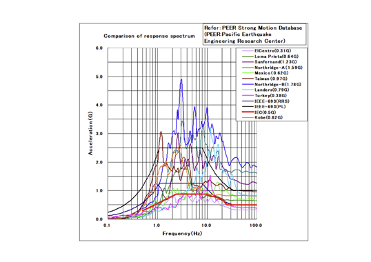
Transients and very fast transients are high frequency electrical disturbances that occur in power systems, and which can lead to degradation of components such as bushings. Transient voltages are created mostly from switching operations of breakers and disconnector operations in gas insulated switchgear but also from harmonics generated by power electronics.
With progressive digitization of the grid, more monitoring equipment is being added. In the case of bushings, this connects to the test tap and to the main insulation, which increases impedance to ground. It is crucial to control voltage when the tap of a bushing is not solidly grounded to prevent the operating voltage or transient voltages from reaching dangerous levels which can put the bushing at risk. Mitigating this therefore requires effective protection strategies to safeguard the bushing whenever online monitoring is used.
This edited contribution to INMR by Henrik Löfås and experts at Hitachi Energy in Sweden explains that risk of failure can be reduced if connection of online monitoring equipment is done using a protection device that can maintain low impedance to ground. Such protection will mitigate voltage spikes in the tap region within nanoseconds should the bushing experience transient stress during high-frequency events.
Full-scale tests have shown that, without protection, stress in the tap region can increase four times compared to directly grounding the bushing. With the protection device, however, stress is close to directly grounding the bushing, independent of what is connected to the tap. Since this protection device is crucial, a routine test was developed to secure quality of every unit.


A high voltage (HV) bushing is used to carry the current at high potential through an earthed wall or transformer/reactor tank. High voltage bushings of the capacitance graded type consist of 3 primary components: an outer insulation for minimizing creepage currents and preventing external flashover; an inner insulation (capacitance graded core, main insulation) for distributing electrical field; and a conductor system for carrying the current. In the inner insulation there are several very precisely positioned, coaxial layers of conducting material in an insulating web.
Grounding of a bushing’s main insulation is done either by connecting the outmost conducting layer to the mounting flange, or to an external tap. Bushings designed according to IEC 60137 or IEEE C57.19.00 have either a test tap or voltage tap for grounding. For a test tap, the outmost conducting layer of the main insulation (C1) is connected to the test tap and the capacitance between the outmost conducting layer and flange (C2) is grounded during service.
For a voltage tap, the second outmost conducting layer of the main insulation is connected to the voltage tap, forming C1. The outermost conducting layer in this case is a so-called C2 layer, which is permanently connected to the grounded mounting flange. The capacitance C2 is thus between the second outermost conducting layer and the outermost conducting layer. In this case there is also a C3 capacitance between the outermost conducting layer and the mounting flange.
During service it is of utmost importance that the main insulation be grounded. This can be done in several ways, either via the lid when closing the tap, a grounding spring inside the tap or permanently connecting the main insulation to the grounded mounting flange (see Fig. 1 left). The latter is the most robust solution but also eliminates the possibility of condition assessment of the main insulation.

In service, bushings can be exposed to transients, very fast transients (VFTs) or other high-frequency events. Transient voltages are created mostly from the switching operations of breakers especially in gas-insulated switchgear (GIS) applications. With introduction of more distributed renewable generation (DERs) into the grid, more sources of harmonics and transients are introduced as well. The DERs are varying in nature with rapidly changing load profile as well frequent energization/de-energizations. VFT and harmonics are also increased with introduction of more power electronics in the grid.
For safe operation of the bushings under these conditions, it is important to have a low impedance between the main insulation and ground. It has been shown in several earlier studies that high impedance to ground can be the cause for bushing failure when exposed to high-frequency events. In cases with failures due to high impedance to ground, these failures most often occur in the tap region, cables connected to the tap or between the outmost conductive layer in the main insulation and ground. Internal high voltages between a bushing’s outermost conductive layer and the mounting flange originate from two different transient behaviors.
One is when the external system generates a high frequency oscillation with a frequency close to resonance frequency of the test tap inductance and the outermost layer capacitance to the flange. The other is due to the fast rise time of the transient voltage, the voltage over C2 will be a capacitive voltage division proportional to the transient step, due to that the high impedance to ground gives a longer time constant to discharge the capacitive circuit. Rise times on the order of a few nanoseconds have been measured from SF6 breakers close to a bushing. Both problems cause a breakdown in the insulation system.
With growing digitization of power grids, monitoring equipment is being connected to bushing taps to measure properties of the main insulation such as capacitance, C1, loss factor (tan δ) or partial discharge. Condition assessment in the field can reduce risk of failures, if performed properly.
While the most sensitive methods for condition assessment need to be performed offline, to avoid outages and follow trends in real time under service conditions, online monitoring equipment is being used. But this equipment connects to the tap of the bushing, increasing total impedance to ground and hence increasing risk of failure in service (see Fig. 1 right). Moreover, connection to the inner components of a capacitance graded bushing through the tap removing the cover from the tap exposes the tap to a new physical environment controlled by the monitoring equipment. These factors should be carefully considered during implementation of any monitoring equipment.

To mitigate some of the risks associated with external monitoring equipment, a device has been developed that protects the bushing from overvoltages in the tap region due to the added impedance from the external equipment. The bushing tap protector (BTP) and the initial testing results have previously been presented. The focus here will be on a special set-up built to replicate VFTs and the routine test that verifies function of each device delivered.

Background & Design
Maintaining low impedance to ground of the tap is of utmost importance. An increased impedance lowers the frequency of internal resonances in the bushing, making it more susceptible to interactions with external disturbances and VFTs. If a breakdown is triggered by a high electric field resulting from the interaction of external and internal resonances, the energy stored in the internal resonance circuit can lead to local breakdown in the bushing’s insulation system. Although the energy is not particularly high, multiple events over time are typically required before a short circuit to the conductive layers occurs. This observation aligns with field experience, where breakdowns are not attributed to a single VFT event but rather require multiple events over time.
It is crucial to control the voltage when the tap of a bushing is not solidly grounded to prevent operating voltage or transient voltages from reaching dangerous levels. Acceptable voltage levels vary among bushings depending on their specific design. While most monitoring systems incorporate voltage protection mechanisms, it is essential for users to verify that the scheme selected offers adequate long-term protection.
Extensive studies were carried out on devices available on the market, but none fulfilled the criteria required by one of the major bushings manufacturers. Therefore, a need was identified to develop a device to safeguard bushings.
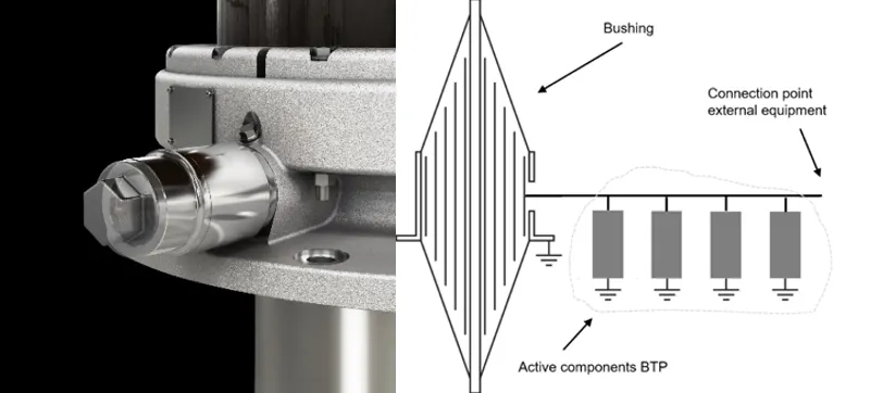
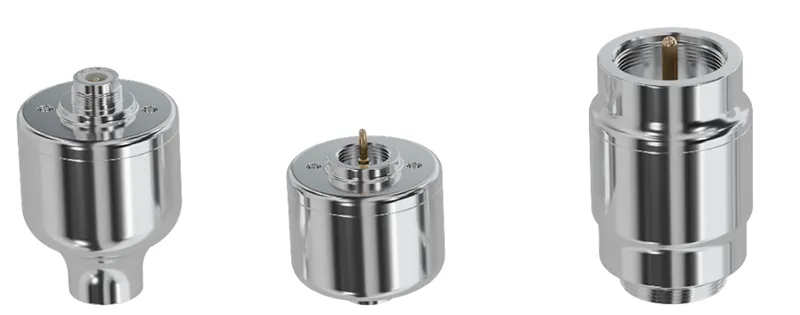
Fig. 2: Illustration of one type of BTP mounted on bushing (left) and principal layout of active components of BTP (right).
The main requirement for the bushing tap protector (BTP) is to reduce this inductance to ground during transient events to protect a bushing. It must also be transparent to signals of both high and low frequencies at voltage levels below 200 V so as not to interfere with monitoring signals. This means that the protection cannot load the tap either resistively or capacitively during normal operation. In addition, the protection needs to be rapid enough to handle the fast rise times of VFT (1-10 ns) as well as slower transients in the range of a few microseconds. It also needs to handle surge currents of up to 40 kA while limiting transient pulses inside the test tap below the withstand level of the insulation – all while lasting the lifetime of the bushing.
The BTP developed consists of 4 parallel branches of components to keep inductance low and increase its robustness and reliability. Each branch is identical and consists of different components such as fast acting gas discharge tubes, transient voltage suppression diodes and standard resistors, mounted on a single circuit board to make the design both compact and robust. Fig. 2 depicts the layout together with an illustration of one type of commercial BTP mounted on a bushing. Different variants of BTPs exist to accommodate different tap designs but all with identical electronic circuit boards (see Fig. 3).
Full-Scale Testing
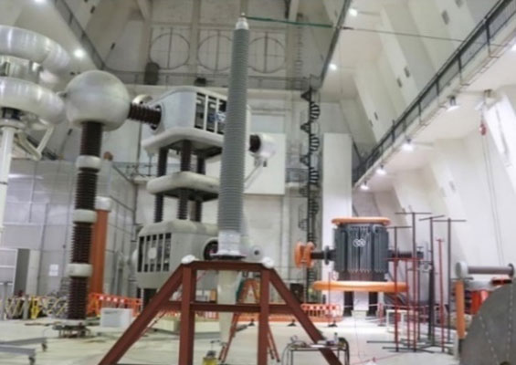
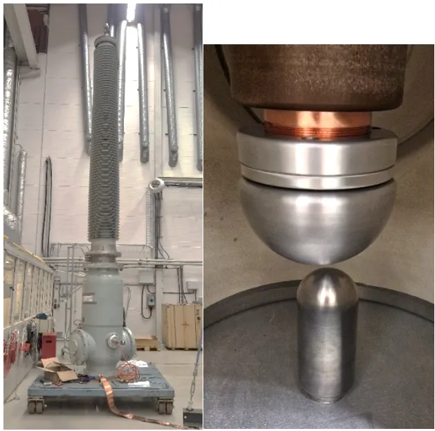
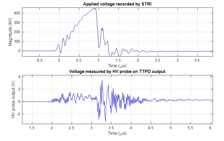
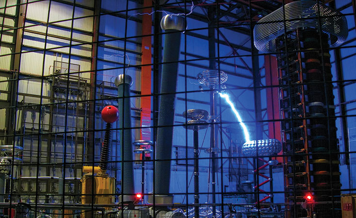
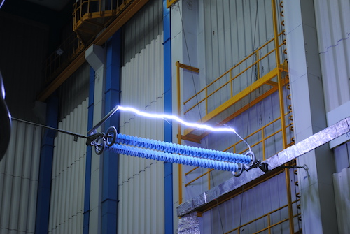
To verify the BTP during a VFT event, a test set-up was built in an HV test facility. As test object, a 550 kV air-oil type RIP bushing was used together with a GIS tank. The bushing was mounted in the GIS tank with the oil side in the SF6 environment. Between the bushing end terminal and the bottom of the earthed tank, two electrodes were mounted, and a spark gap was set (see Fig. 4).
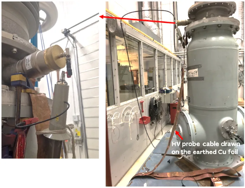
The BTP was fitted to the test tap by hand. A tailor-made adapter for easy connection of BNC cables to the test tap was then used to connect a 25m double shielded cable simulating monitoring equipment. To enable connection of both probe and a cable a BNC T-connection was used. The high band width HV measuring probe was connected as close as possible to the BTP (see Fig. 5).
Testing with VFT creates many electrical disturbances and it is very challenging to get a measurable signal, which makes VFT testing difficult. Ensuring a good earth connection close to the mounting flange is important and as well as thoroughly shielding the cable from the probe to the oscilloscope to lower the disturbances. However, noise generated by the VFT test is still picked up in the measurement signal complicating the interpretation of the results. To fully analyze the results a simulation model was set up to verify the stress in the tap region C2 against the measurement and give more insight into the function of the protection device.
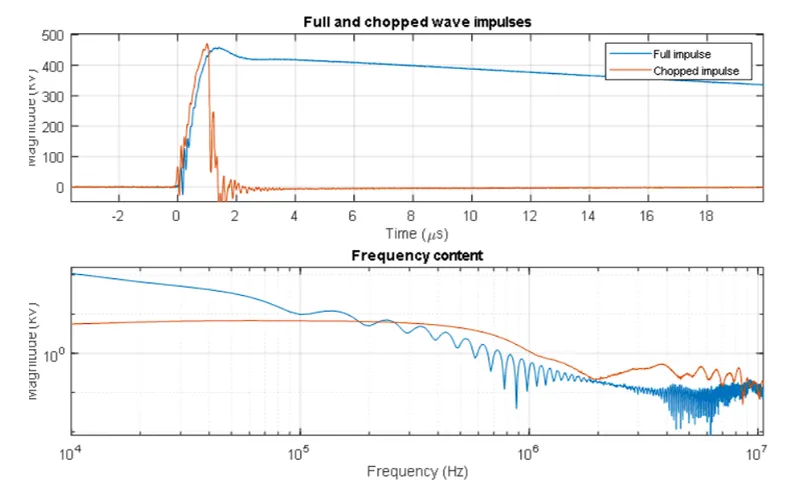
To tune the test set-up, a specially designed current shunt was used to measure the current during a VFT at chopped and full impulses. It may be noted in Figure 4 that the chopped impulse carries more energy in the MHz region testifying why it is more dangerous than the full impulse. Moreover, the current shunt was used for tuning the setup where for the chopped impulses (peak around 500 kV) a maximum current of 10-20 kA passed though the test tap with a ringing frequency around 7.5 MHz. It is also apparent that there is some oscillation on the rising edge of the applied impulse as well as a wedge like feature on the fall at the chopping which is believed to be an art-effect of the spark gap inside GIS.
After the tuning of the VFT test circuit with current shunt measurement described above, the BTP was mounted on the bushing test tap, as shown in Fig. 5.
The BTP device was connected to the bushing test tap and open circuited, i.e., its output was open and not connected to anything. Both full- and chopped-wave impulses (ten shots each) were applied. The voltage was measured on the output from the BTP, and it was concluded that the signal was cut at about 4 kV after less than 10 ns. The device has a fast reaction time. But due to the very fast rise/decay times (high dV/dt) of the VFTs, or in this case the chopping, there will be an overshoot before voltage is clamped. In the case of chopping here, the decay time is on the order of 3.5 MV/µs.
The most probable scenario is that once a bushing monitoring system is connected to the test tap via a BTP, it adds an impedance due to a cable and/or measurement system or adapter. To test this, 2 situations were simulated using a 25 m double-shielded cable.
• First, the 25 m cable was terminated with a short-circuit at the end to simulate bushing monitoring hardware failure;
• Then, the cable was terminated with an open circuit to account for normal operation with very high input impedance of a bushing monitoring system input module.
There were a few chopped impulses applied with shorted 25 m cable and ten shots with the open-ended cable. In both cases, the HV probe output hit maximum of 4 kV around the chopped portion of the impulse. Fig. 7 shows one of the impulses with the short-circuited cable. There is no marked difference between the tests with only the BTP itself and the added 25 m long cable. Thus, all influence of the added impedance from the cable is removed by the BTP and not seen by the bushing.
In total, the bushing and BTP experienced more than 20 VFT pulses. After the test was complete, they were routine tested, and condition assessed. Both showed no deviation compared to new units.
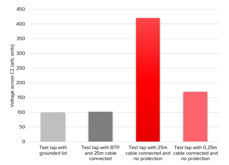
To fully interpret results from the test, a simulation model was used to estimate voltage inside the test tap where breakdowns are usually found should there be too high impedance to ground. The tap is modeled by its inherent inductance and the GIS chamber and VFT spark gap are modeled by a transmission line, a spark inductance and a varistor simulating the spark voltage. A switch is used as an ignition of the spark gap. Connection wire and conductive layers in the main insulation are simulated by their inductance and mutual inductance. Mutual inductances between the impulse generator, voltage divider and the bushing are also added.

The result from the simulation matches the measured curves in the case with the open cable end. Fig. 8 shows results from the model where peak voltage at C2 during the VFT test is compared for different situations. The voltage over C2 is normalized to the voltage the model gives when the bushing is grounded via the standard tap lid and then compared to different scenarios.
• Bushing grounded through the BTP;
• Bushing grounded through BTP with a 25 m cable connected;
• Bushing grounded through a 25 m cable;
• Bushing grounded through a 2.5 m cable;
• Bushing grounded through a 0.25 m cable.
As can be seen, connecting the BTP increases the voltage inside C2 slightly (around 5%) and it is no different having the long cable connected. Having a cable connected without the BTP increases voltage at C2 already 50% for a 0.25 m cable and around 4 times with a cable of 2.5 m or longer. The increase of 5% with the BTP is from the added impedance from the device, still this increase is negligible compared to connecting the cable where risk of failure in the bushing will be increased significantly already for such a short cable as 0.25 m.

Routine Testing
In addition to design and climatic tests for robustness described in the product documentation, each BTP is tested before delivery using a unique test set-up based on the principle presented earlier. An impulse generator together with an impedance-matched test circuit generates a well-defined pulse to simulate a medium high surge current. The response is measured by a high bandwidth oscilloscope.
The test circuit is designed to create voltage steps up to 12,500 V with a rise time below 4 ns, which give a dV/dt of 3.1 MV/μs, which is very close to the rise times in the full-scale setup. With this fast rise time the BTP is expected to arrest the pulse at approximately 1000V.
The BTP has two systems of protection that are always active:
• The first is fast acting and designed to quickly arrest the highest frequency surges;
• The second offers great robustness but responds more slowly, activating only after the first system has engaged.
The components are tested individually by applying several charges at different voltage levels.
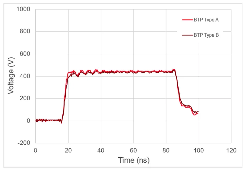
• In the first test a low voltage impulse of 300V-400V is applied that should pass the protector unchanged – a crucial aspect since the protection must not disturb the signal picked up by the online monitoring system (see Fig. 9).

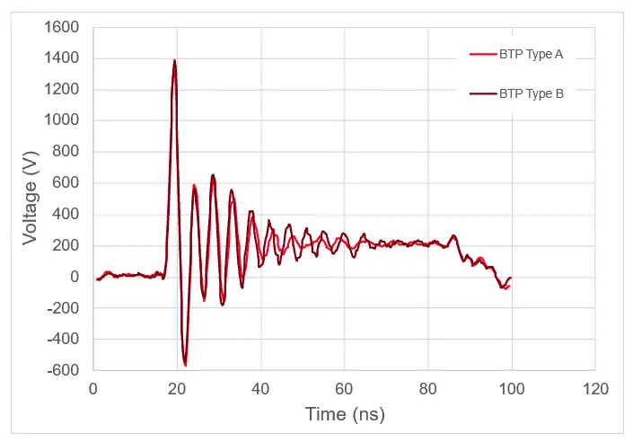
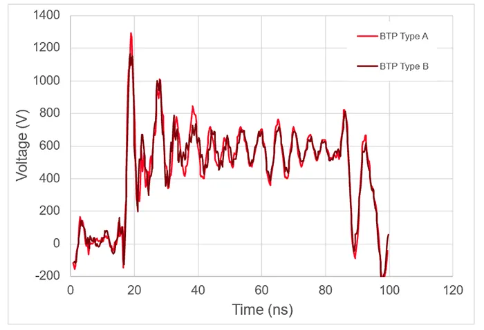
• In the second test a voltage of 2000 V is applied, which is set to trigger only the fast-acting components of the protection. The pulse is arrested at approximately 1400 V and stabilizes around 200 V (see Fig. 10).
• For the third test a high voltage surge of 12,500V is applied which will trigger all components in the BTP. The pulse is arrested at 1200V and stabilizes at around 600V (see Fig. 11).
For each of the tests, criteria are set for the response of the BTP. Should any component in the protection be faulty or outside specification, this will be detected by an output signal that has diverged from the expected values and that device will be rejected.
Conclusions
With digitization of the grid, monitoring is added to power equipment. Monitoring on a bushing connects to the test tap and the main insulation, which will increase the impedance to ground. It is crucial to control the voltage carefully when the tap of a bushing is not solidly grounded to prevent operating voltage or transient voltages from reaching dangerous levels that can put the bushing at risk during operation.
It has been demonstrated above that risk of failure can be lowered if the connection of online monitoring equipment is done via a protection device that can maintain a low impedance to ground. The protection will mitigate the voltage spikes in the tap region within nanoseconds if the bushing experience transient stress during high-frequency events. Full-scale tests have shown that without protection the stress in the tap region can increase 4 times compared to directly grounding of the bushing. With the protection device, the stress is close to directly grounding the bushing independent of what is connected to the tap.
The bushing tap protector is available in different variants, depending on bushing tap design, and all have equal electronic circuit boards. Each tap protector is routine tested in a special test set-up to secure quality of its internal components and functionality of each device.
References
[1] CIGRE WG A2.37 , “TRANSFORMER RELIABILITY SURVEY,” CIGRE, 2015.
[2] CIGRE WG A2.43, “Transformer bushing reliability,” CIGRE, 2019.
[3] S. Gobi Kannan and K. Hafizzudin, “RIP Bushing Service Experience & Replacement Strategy at TNB,” INMR 2022 World Congress, 2022.
[4] S. Gobi Kannan and Z. Hafizzundin, “Evaluation of Bushing Performance for Shunt Reactor & GIS Connected Transformer: Application in ASEAN Grid,” INMR, 2023.
[5] K. Johansson, U. Gäfvert, G. Eriksson and L. Johansson, “Modeling and Measurements of VFT Properties of a Transformer to GIS Bushing,” CIGRE Sessions 2010, 2010.
[6] L. Jonsson, “Advantages vs. risks with on-line monitoring of transformer bushings,” 2021 IEEE Electrical Insulation Conference (EIC), 2021.
[7] H. Löfås and R. Hedlund, “Impact of VFT on Bushings & Necessary Protection When Using On-Line Monitoring,” IMMR, 2023.
[8] G. -M. M. e. al., “Time and frequency characteristics of very fast transient overvoltage in ultra high voltage substation,” IEEE Trans. Dielectr. Electr. Insul., vol. 24, no. 4, 2017.
[9] H. Löfås, R. Berg, L. Jonsson and R. Hedlund, “Risk Mitigation through Transient Protection of Transformer Bushings when Using Online Monitoring,” in 2024 IEEE Electrical Insulation Conference (EIC), Minneapolis, 2024.
[10] Technical Guide Bushing Tap Protector (1ZSC000563-ACS), Hitachi Energy, 2025.