The electric field method has been used for over 30 years to test and verify the condition of energized porcelain and composite insulators on overhead transmission lines. Early detection of defective insulators avoids risk of significant problems and enables scheduled maintenance as well as maximum safety prior to live-line work. The methodology utilizes measurement of E-field distribution along insulators to detect presence of any conductive defects as well as record and display their severity and location.
This edited past contribution to INMR by Eng. Charles Jean of Positron Power in Canada reviewed how this methodology evolved and how it can prove effective in detecting even small defects not always identified using other inspection techniques. An overview is also presented of some of the most common problems encountered on porcelain and composite line insulators, including moisture ingress, carbon tracking, surface contamination and manufacturing defects


Potential difference gradient along an energized insulator creates an electric field (E-field) that surrounds the insulator in concentric circles. Any conductive defect, internal or external, causes distortion in the strength of that E-field in the immediate vicinity of the defect. Moreover, length of that distortion is directly proportional to size. This enables detection of the size of the defect, provided the sensor module is sufficiently sensitive. Location of the defect and its length are measured as the sensor moves along the length of the insulator.
This methodology has been refined over the years to detect even small and floating defects and display and record their size, type and location. Significant work has recently been done with the goal of allowing such data to be processed instantly and yield a graphic that displays the relative size and location of defects, enabling the user to ‘visualize’ them. Measurements obtained from periodic checks on in-service energized insulators can be systematically downloaded and stored to provide a diagnostic database. This database can then be used to determine compromised insulators with defects and can also predict degradation over time based on quantifiable data collected.

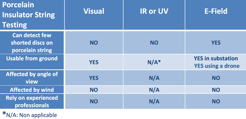
Since this methodology does not depend on measuring heat or corona discharge, readings are not impacted by factors such as wind, noise, sunlight or the sensor’s angle of view. Any drop in E-field surrounding an insulator due to a defect is measureable from any angle. Moreover, energized porcelain insulator strings with only a few defective bells do not generate heat or corona and no IR or UV is produced across a shorted bell in the absence of voltage. Similarly, energized composite insulators with small or floating defects might not generate much heat or UV until the defect becomes relatively large.
Methodology
Since the useful service life of insulators is hard to predict, they must be verified periodically to ensure line reliability. Several testing methods have been used for this purpose, each with its own relative strengths and weaknesses. A reliable and safe insulator testing technique:
• alerts line personnel instantly of any conductive defect that is dangerous by means of a visual alarm (i.e. safe or not safe to work on the line);
• includes automatic counting of the insulator’s sheds or bells and records measurements and their locations in a quantifiable database;
• does not depend on climatic conditions or is affected by angle of view;
• has high sensitivity to detect even small defects (including floating defects) before they produce detectable IR or UV radiation;
• does not rely on judgement of testing personnel to identify defects;
• is safe to operate on energized lines using an isolating hot-stick or drone;
• can obtain statistics on performance and degradation of installed insulator assets;
• transmits data immediately after a scan via long range Bluetooth link and can export JSON formatted data to an existing Asset Management System.
Electric field measurement can be applied for porcelain, composite and glass insulators although in the last case the methodology is used for contamination assessment since shattered discs are easily detected visually.

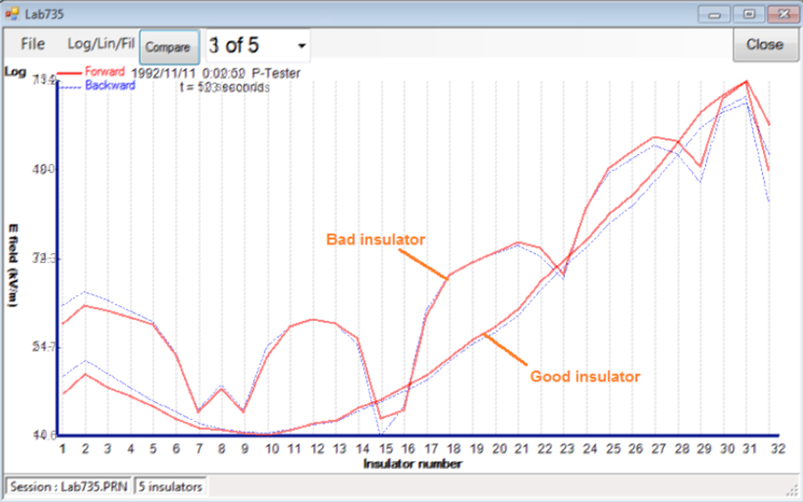
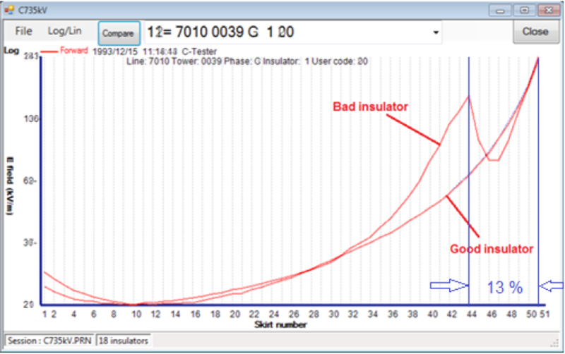
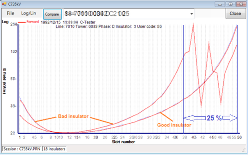
A. Porcelain Insulator Testing
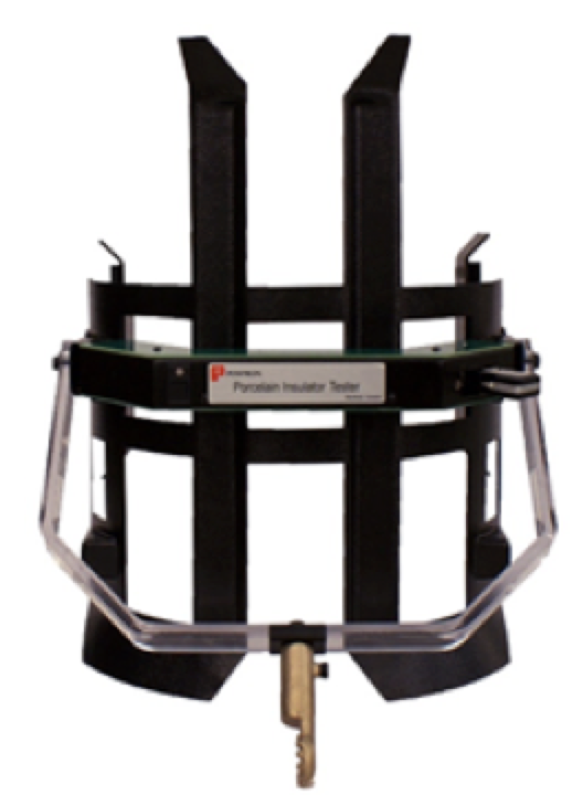
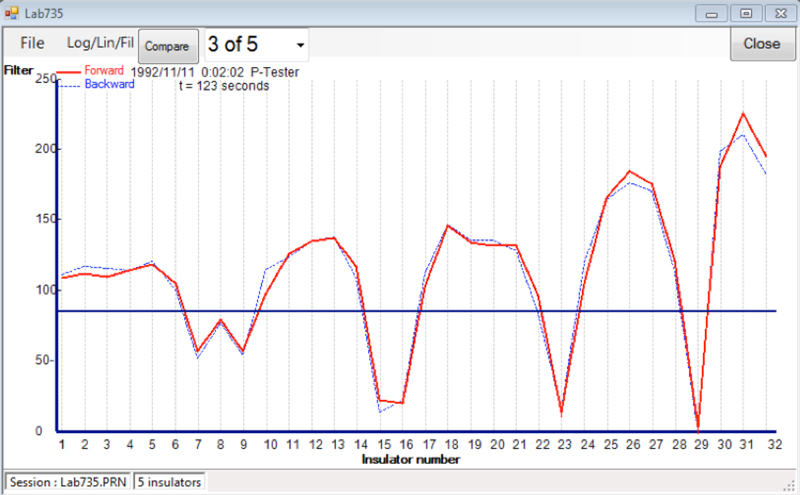
Fig. 3 shows a graph that compares a sound versus a defective porcelain insulator string using a default logarithmic scale. A filter scale simplifies interpretation (see Fig. 4). In this case, changing the defective discs on this insulator string is recommended at a convenient scheduled time.
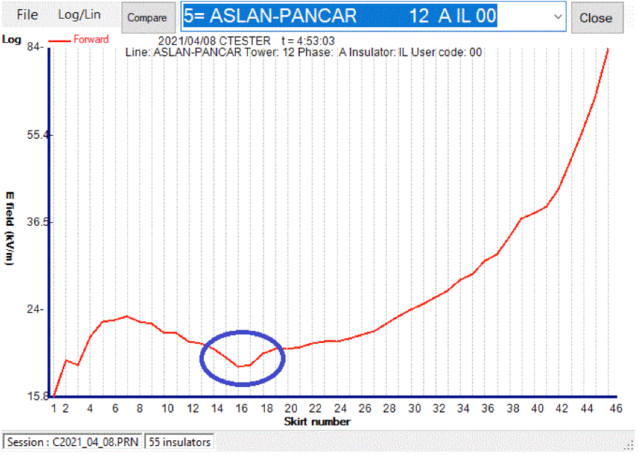
B. Composite Insulator Testing
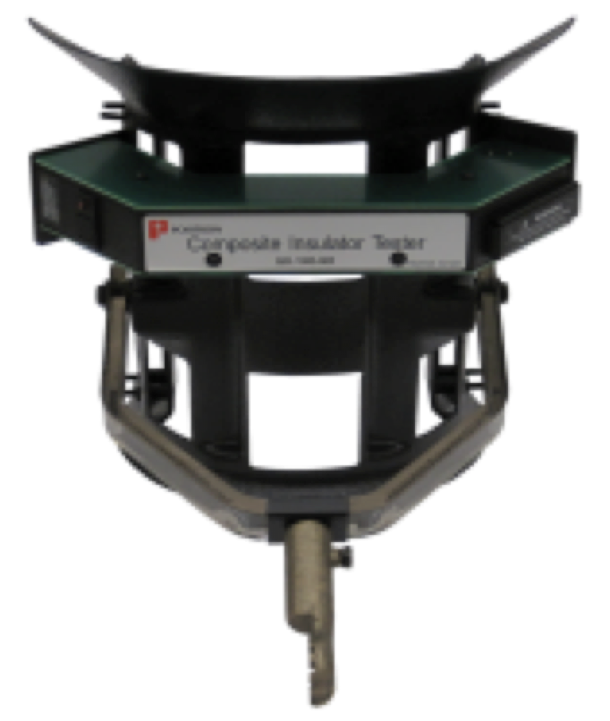
The composite insulator tester uses the same method as the porcelain tester however its sled and probe size is smaller to accommodate smaller shed diameters.
A reading of electric field is taken at each shed. Any defect usually spans over more than a single shed. Conductive defects are not always visible to the naked eye and constitute a danger for proximity workers. These conductive regions can be either ‘connected’ or ‘floating’. Connected defects occur mostly near the HV end of an insulator due to the carbonization facilitated by the presence of the strong electric field. These defects grow toward the grounded end of the insulator.

The connected defect identified in Fig. 7 will not generate IR or UV radiation because its length is shorter than 25-30% of the insulator’s length (i.e. the length at which flashover can occur). It is therefore safe for proximity of workers. The E-field method therefore alerts utility personnel that this insulator needs to be changed or at least monitored over specific intervals.
Connected defects equal to or longer than 25-30 % of the insulator length are deemed electrically unsafe for work in the vicinity because a surge on the line can trigger a sudden, dangerous flashover. This insulator should be replaced as soon as possible under de-energized line conditions. Such defects typically occur at the interface between the fiberglass rod and the polymeric sheath material. Discharges due to the electric field occur and carbonize the rod, thereby weakening it mechanically by burning fibers. Carbonization progresses gradually along the rod thus reducing total effective insulating length of the insulator. This dangerous condition can be caused by carbon tracking and/or moisture ingress. Such a length of defect (i.e. >25-30%) might generate infrared radiation. Ultraviolet radiation may also be detectable if the ionization reaches the external surface of the polymeric housing and the camera is looking at the affected side of the insulator. Fig. 9 shows a small floating (not connected) defect.
The E-field methodology can detect even small floating defects where no IR or UV radiation has yet been generated. For example, this method can detect floating defects with as little as a 3-shed spacing. Such an insulator is deemed safe for proximity of workers and can be scheduled for replacement under an energized line condition.
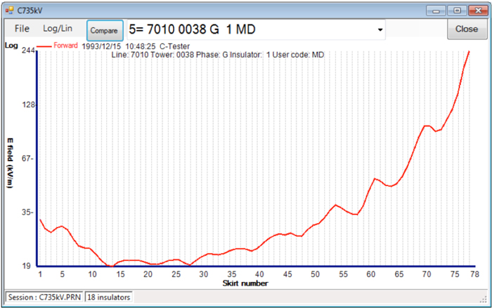

Fig. 10, by contrast, shows an insulator that is unsafe for worker proximity and should be replaced as soon as possible under a ‘dead line’ condition. The problem here might, for example, be due to a manufacturing defect.
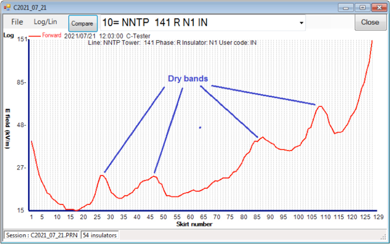
In the presence of humidity, contaminated insulators can produce multiple dry bands (see Fig. 11). To distinguish between a defective versus a contaminated insulator, it is necessary to compare findings with other phases on the same tower since the same contamination will be present there as well. The highly contaminated insulator in this case is deemed ‘unsafe’ for proximity of workers and should be cleaned and re-tested several hours later.
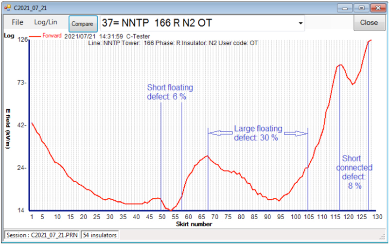
The insulator shown in Fig. 12 is deemed ‘dangerous’ because the total length (44%) of floating and connected defects, which were not visible, is higher than 25-30% of total insulator length. The two floating defects do not generate infrared because they are not connected to the HV or ground end. The long (30%) floating defect, however, may generate detectable ultraviolet. The short connected defect does not generate UV and IR radiation because its length (8%) is less than 25-30% of total length.
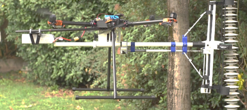
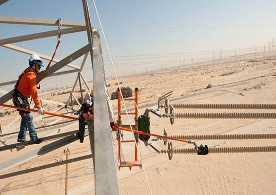
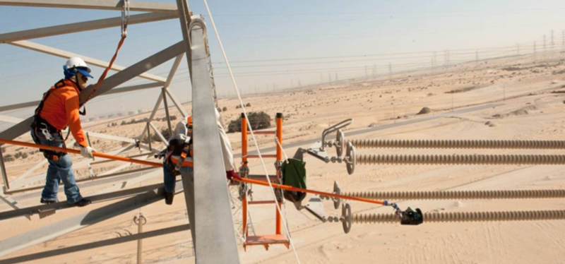
While the E-field measurement method is accurate and reliable for early detection of insulator defects, one of its disadvantages is the time required for personnel to climb towers or use a bucket truck to manually move the sensor at the end of a hot stick. This has led to development of a drone that flies to the insulator and moves the sensor along its length (see Fig. 13). This enables early detection reliability as well as minimal use of manpower. The drone for composite insulator testing is currently undergoing trials in Europe.

C. Substation Insulator/Bushing Testers
The E-field method is now also being applied to test different types, shapes and sizes of insulators installed at substations, where the consequences of failed insulators can be far reaching. The sled in this case is replaced by skis and use of a roller or isolating tab. Insulator bodies can have various shapes and dimensions yet the tester is still effective. While suspension insulators on HV lines produce similar graphics, irrespective of insulator manufacturer, size or voltage rating, the graphics produced from insulators at substations follow different patterns. The principle of E-field variation remains applicable but the algorithms are more complex.
Summary
The E-field methodology for testing insulators has a record of high sensitivity, reliable results and safe operation and can be used on many different types of insulators. Systematic investigation has been carried out focusing on its ability to point out even small yet critical defects and its sensitivity to different types of damage and contamination. Extensive testing in high voltage laboratories as well as on energized lines has been performed at up to 1 megavolt (phase-to-ground).
Programming and algorithms in the built-in processor enable the device to instantly and accurately report and store data and display it in a user friendly way. Introduction of drones will simplify how the testers are operated. In addition to preventative maintenance and early detection of insulator defects, the E-field testers are used as a safety tool prior to live line work. E-field testers have now also been applied for condition monitoring of insulators at substations.
References
[1] M. de Nigris, F. Tavano, F.Zagliani CESI; “Diagnostic Methods of Non-Ceramic Insulators for H.V. Lines”
[2] D. H. Shaffner, PG&E; D. L. Ruff, BPA;
H. Vaillancourt, Independent Researcher
“Experience with a Composite Insulator Testing Instrument Based on the Electric Field Method”
[3] G. H. Vaillancourt, IREQ; S. Carignan, IREQ;
Jean, Positron
“Experience with the Detection of Faulty Composite Insulators on High-Voltage Power Lines by the Electric Field Measurement Method”