Utilities and large industrials all have varying degrees of condition assessment program to ensure the safe operation of their transmission assets. Insulation review and life assessment is an important part of such programs. In so doing, it is important to know how best to look for the tell tale signs of damage as well as to understand why this is occurring. While there are a variety of methodologies for inspecting insulation, few are as rapid and cost-effective as simple visual observation conducted by experienced inspectors.
This edited contribution to INMR by Dennis Schlender, a transmission line specialist with of DBS Energy Services in Canada, offers insight into practical visual field inspection and related condition assessment of transmission insulation and components. The goal is to minimize related financial and management burdens while helping complete condition assessment in as timely and efficient manner as possible. While this approach does not eliminate possible need for additional more formalized inspection methodologies, it can help identify and prioritize the issues that will subsequently need to be addressed.


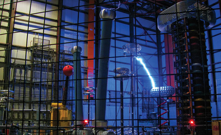
A large number of transmission projects were completed during the 1950s, 60s and 70s when rapid expansion as well as interconnection of grids were underway in many parts of the globe. This has now led to a common industry theme of aged infrastructure that is approaching end-of-life. Also underway during these time periods were several technology enhancements in design of transmission components, in particular insulation. Unfortunately, assessors and inspectors charged with inspecting ageing transmission assets are sometimes not sufficiently prepared or fully understand what is needed when monitoring the condition of insulation on overhead lines. While the line inspection process has been improving over recent years, planning for condition assessment projects is often not a high priority in spite of the fact that such data is then used to justify needed improvements in ageing transmission systems. Obviously, utilities have options to complete detailed reviews of insulation performance, such as laboratory testing of samples removed from lines, infrared thermal imaging or daylight corona cameras. However, these can be costly and, too often, budget limitations influence the extent of testing or inspections that take place. As such, better coordinating and consolidating condition assessment programs not only helps reduce costs but also allows for more effective deployment of capital.
Field Inspection
Planning
Efficient planning for field inspections is increasingly important given the challenges in today’s utility environment. For example, regulatory controls over utility budgets are competing with legal liability matter. Moreover, issues such as right-of-way access to lines, weather conditions, landowner needs, requirements for brushing, increased system loading, etc. all start to interfere with one another as competing priorities. This makes it important that thorough condition assessment programs are used to improve the final product planning and budgeting process while also reducing utility risk.
Training
Utilities and large industrial customers sometimes spend insufficient effort to train inspectors. Contrast this with what is spent on actually undertaking an inspection or the cost of possible outages related to sudden device failures. Such an imbalance is a missed opportunity to improve the inspection process itself as well as the accuracy of information being collected. Since financial decisions are generally based on this data, all reasonable efforts to improve the quality of line inspections should be implemented. Often, inspections are carried out by linemen using basic tools and equipment who make a judgement based on limited experience. But qualifications needed for inspectors may not fit either with engineers or linemen inasmuch as successful inspectors need some exposure in both disciplines. Training can help fill such gaps.
Questions arise as to what constitutes a good transmission condition assessment plan. Some utilities feel that a helicopter fly-by on an annual or semi-annual basis is sufficient to ensure a line has been inspected. While helicopter patrol does demonstrate due diligence for major concerns, it does not always provide sufficiently detailed information on the condition of key line components. Helicopter patrols can be supplemented with mounting infrared and corona cameras to significantly improve results. However, given their greater field flexibility, detailed ground inspections are usually better able to allow for an effective and detailed condition assessment. The key issue is ensuring that the detailed ground patrol captures adequate information and assessment on even subtle issues affecting insulation components.
In this regard, a training session, even for experienced inspectors, will help ensure that all required information about a line will be collected, especially given that inspectors also conduct a variety of component inspections apart from insulation. These include condition of pole, cross-arms, conductors, cross-braces, bolts and hardware, bonding and grounding, brushing, right-of-way issues, etc. In respect to the insulation itself, important areas to address during training are:
• Electrical performance is most important yet often taken for granted;
• Visual inspection has to characterize any damage observed;
• Even subtle problems need to be flagged;
• How various problems appear, where to look for them and why they occur
• How to rate and rank various levels of insulation deterioration. Examples can prove valuable to define degree of concern;
• Specific issues that the line being inspected has experienced and review of historical outage records;
• Clarification that not all problems require replacement;
• Each type of insulation has benefits but also varying susceptibility to and mode of failure (e.g. high contamination designs; porcelain; glass; silicone, EPDM or EPR rubbers.

Availability & Collection of Data
Since data collected in the field provides the information needed for planning and estimating costs of any work requirements, ensuring that this data is accurate is critical. Inspection sheets should therefore be evaluated and tailored to fit line type and needed quality of records. A full understanding of the line to be inspected is valuable, along with consideration, from an operational point of view, of any relevant issues that may show up. Detailed insulation records are too often lacking. As such, there should be attempts during inspection to record all pertinent insulation data such as manufacturer, part number, vintage, etc. This is in fact imperative on transmission circuits that are known to have or suspected to be starting to experience insulation problems.
Tools Needed for Inspection
Level of inspection and testing of transmission line insulation should be dictated by specific issues that may have been experienced in the past. Minimum inspection tools specifically related to insulation should include:
• High quality binoculars, preferably image stabilized, of 14x or 16x;
• Digital camera > 16 MP & with good zoom (min. 30x optical). 60x zoom can be beneficial for detailed close-ups;
• Spotting scope.
Rigorous field insulation inspections tools should also include:
• Energized insulator testers for porcelain or glass bells;
• Live line insulator testers for polymeric insulator strings;
• Equipment such as infrared and corona cameras for specific concerns.
Typical Insulation Problems & Issues
As the inspection progresses, a variety of insulation problems may show up, which often depend on manufacturer, vintage, framing configuration, use of or lack of corona rings, voltage level, and type of insulation material. The following examples should be discussed and reviewed during training with inspectors to ensure that a uniform and common recommendation system is adopted. This also provides guidance to inspectors in regard to how initial damage can progress and why it is important to identify.

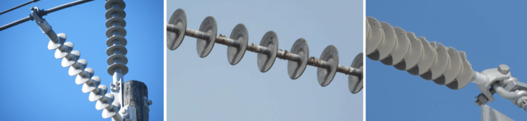
Corona Cutting
Corona cutting can occur on transmission insulators (usually 115 kV/138 kV and above systems) that do not have proper corona protection. Corona cutting starts out as small incisions that can eventually lead to splitting of the polymeric housing that further deteriorates the housing and can eventually even expose the fiberglass core.
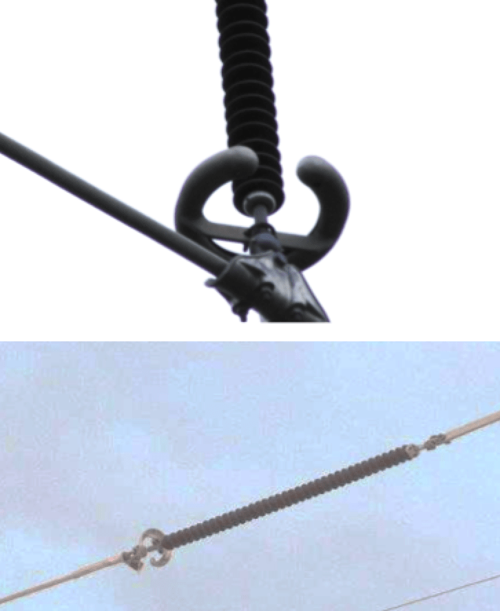
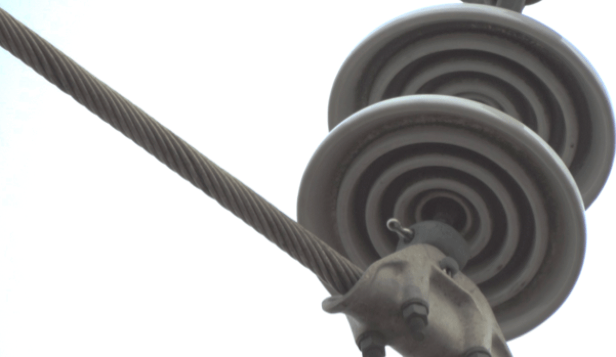
Application of Corona Rings
Utilities worldwide have increasingly come to realize the need for corona rings on composite insulation, even as low as 115 kV & 138 kV voltage levels, to ensure such insulators are kept free of dry weather corona.
Flashover, Lightning & Flashunder
Unfortunately, such phenomena are most recognizable and found after an outage has already occurred. Nonetheless, there are times when this type of damage becomes inherent and the line can still be successfully re-energized. For example, a lightning strike can cause electrical punctures and burn damage with resulting string flashover yet the line can be re-energized at system voltage. Flashunders, by contrast, can occur on polymeric insulators due to excessive torsional loading or seal failure that allows moisture to migrate internally along the rod.

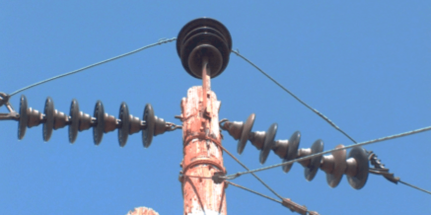
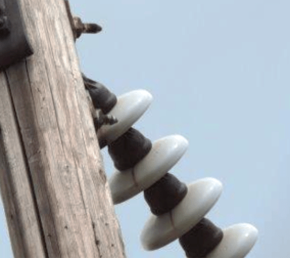
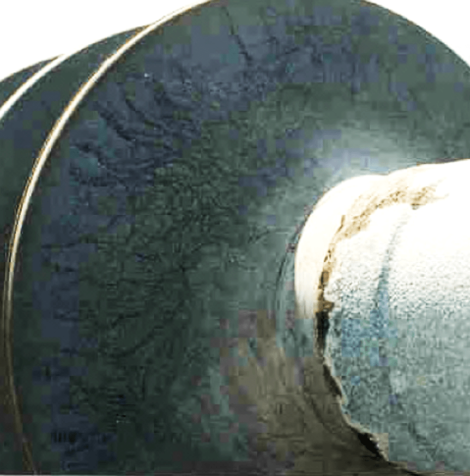
Deterioration of Glaze
As porcelain insulators age due to contamination, UV degradation, weather, etc., loss of glaze will start to compromise insulation ability. Often this will show up as tracking or flashovers under light wetting conditions.
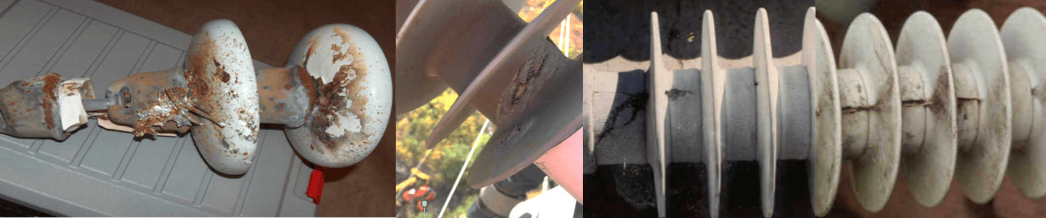
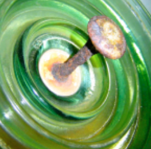
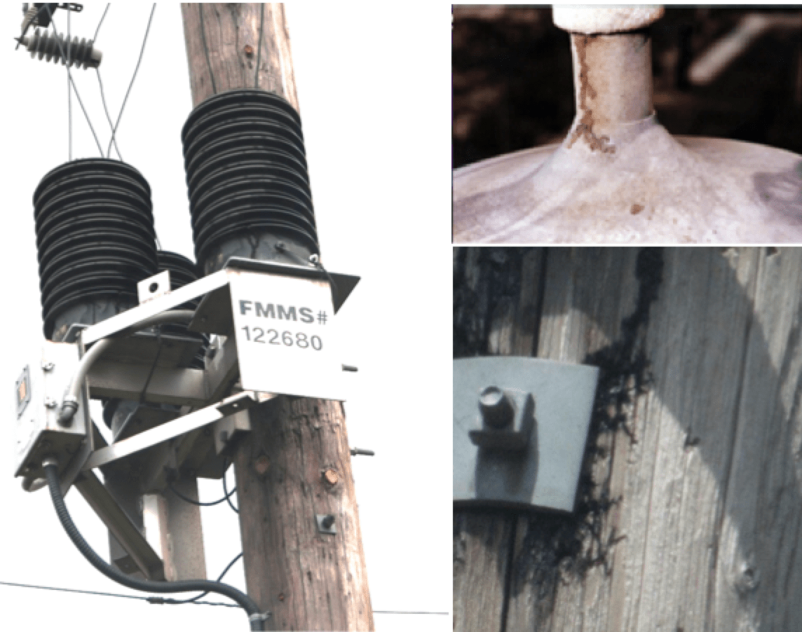
Corrosion
As insulation is exposed to various contamination, weathering and corona activity that creates nitric acid, there will be progressive loss of galvanized finishing on fittings and pins. Generally, galvanized fittings outlast the insulation, however there are times when significant corrosion can develop and lead to specific attack on metallic components. Typically, replacement can be delayed until such time as corrosion is seen to be causing loss of material.
Hardware & Keys
It is important to identify keys that may not have installed fully and which could potentially release a conductor under line galloping or heavy wind load. In older installations, it has even been found that insulators and hardware were equipped with brass keys that could wear and fall out.

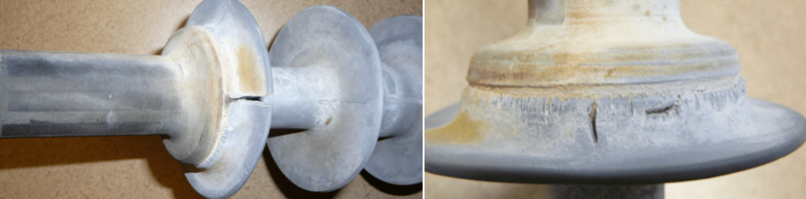
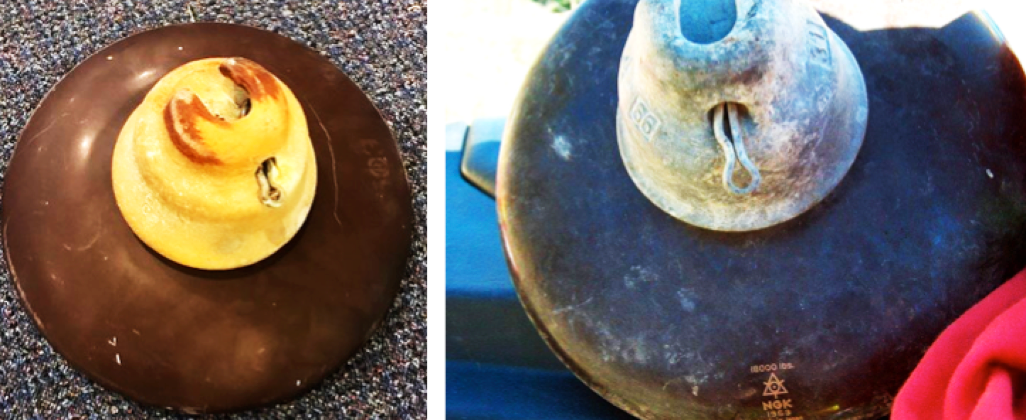
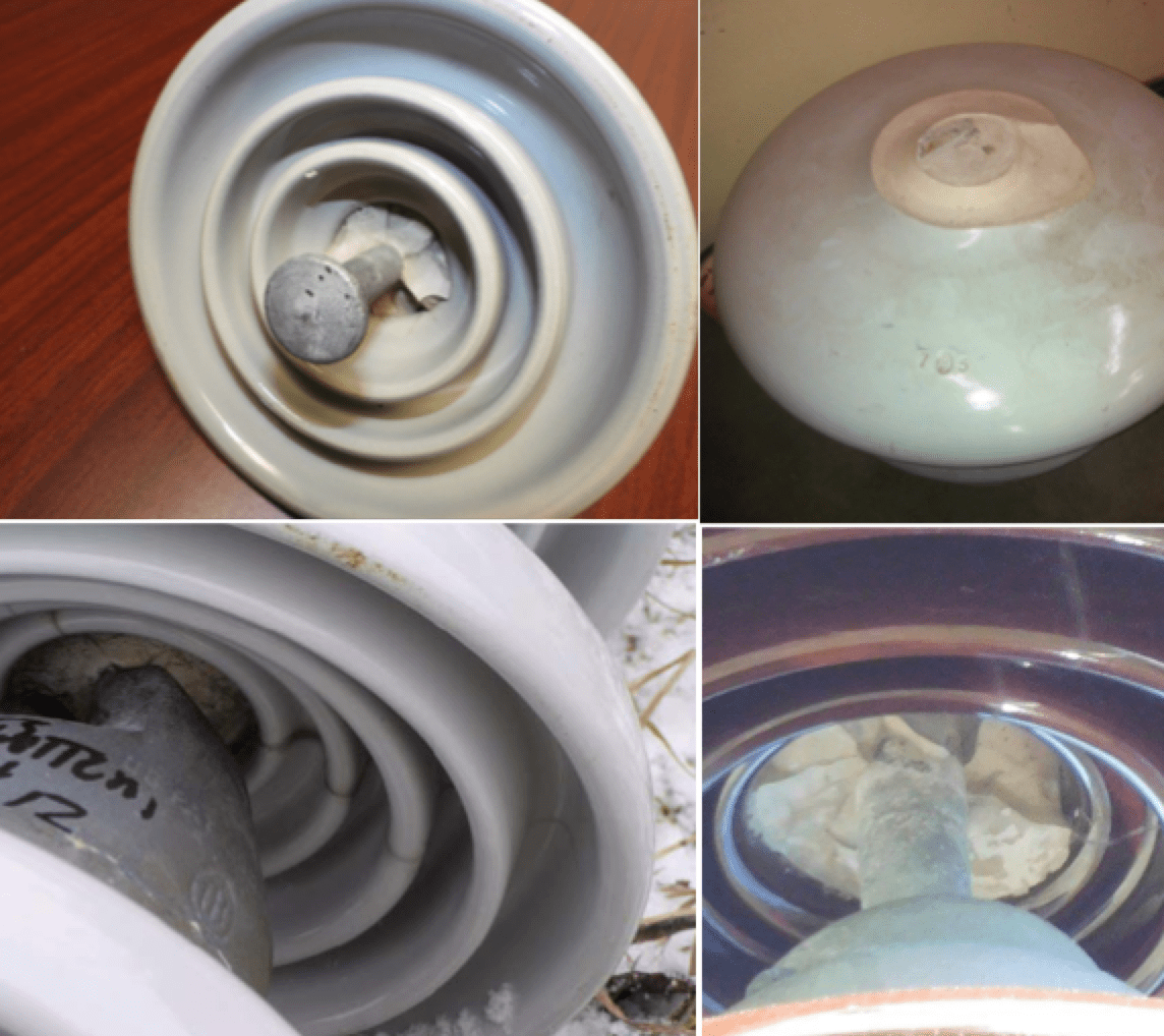
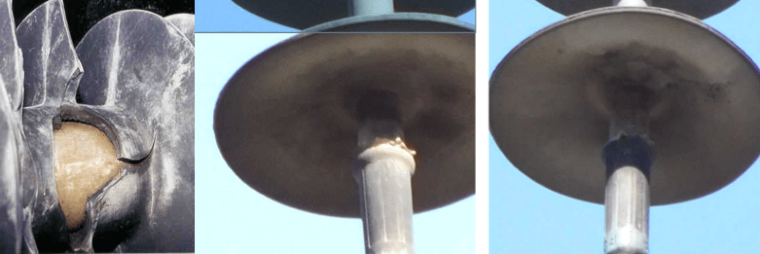
Cement/Grouting Problems
Over the years, some manufacturers have experienced issues with bad formulations of grouting/cement. Expansion, contraction and water migration can compromise the electrical and ultimately the mechanical integrity of insulation. While sometimes difficult to detect, inspection conducted from the proper vantage point should be able to identify such problems. This is another example where it is important to identify insulator manufacturer and vintage in permanent records.
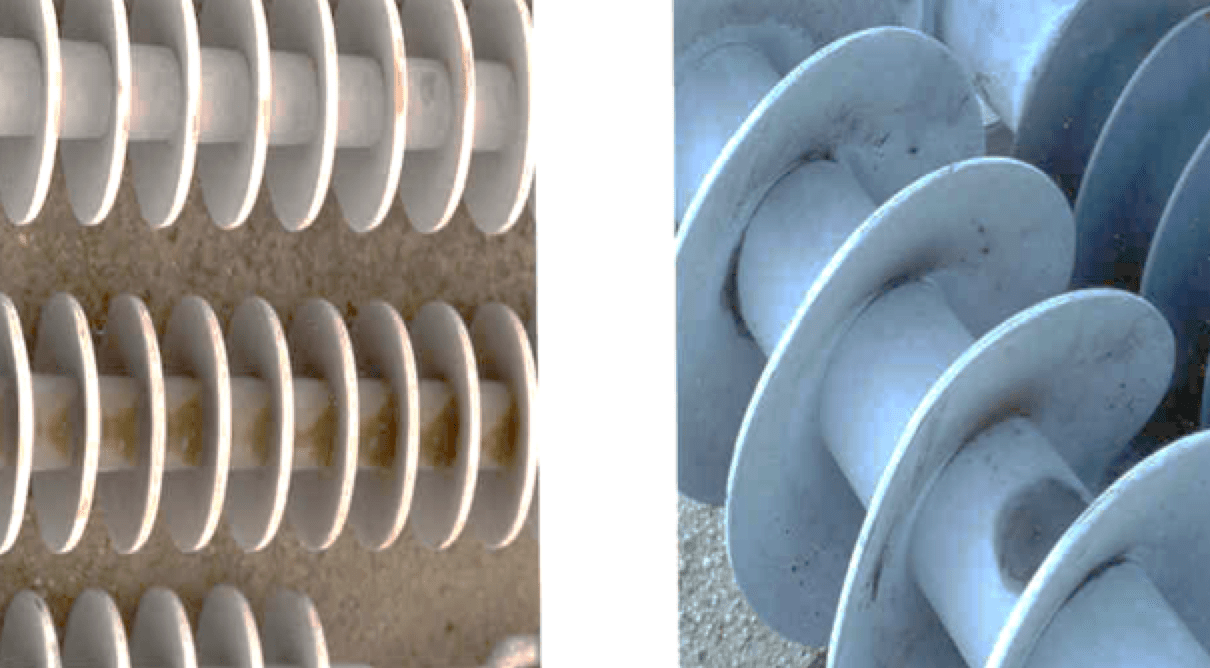
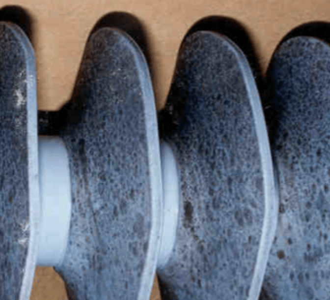
Chalking
Chalking on insulators is not usually an urgent concern but rather indicative of insulation that is starting to age leading to consideration for long-term retirement from service. This phenomenon is generally caused by UV degradation over time. Chalking does not typically show up in the case of silicone polymeric insulators but can be prevalent on EPR/EPDM housings, making these materials less suitable for transmission applications. While chalking may not cause immediate problems, it does allow contamination to accumulate more rapidly and promote greater incidence of water filming on insulator surfaces, i.e. loss of hydrophobicity.

Crazing
Crazing on polymeric insulators is created by electrical activity on surfaces, essentially causing tracking and eventually compromising the insulation. Often, its presence is aggravated by the same factors that initiated it, such as corona activity and UV degradation.
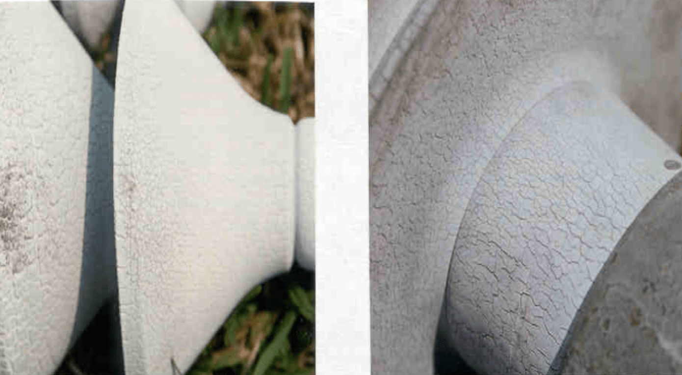
Alligatoring
Alligatoring can develop as crazing becomes severe or as continued UV degradation starts to cause small checking on insulator surfaces. This type of damage usually signifies that an insulator has now reached end-of-life.
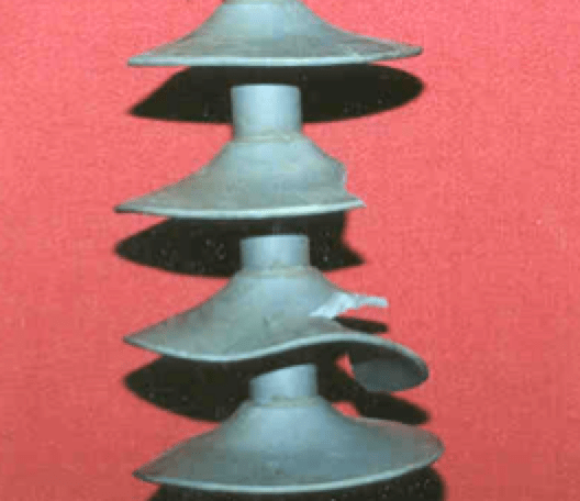
Damage to Sheds
Shed damage can be a matter of confusion for inspectors in terms of potential impact on performance. While minor shed damage may slightly reduce insulator contamination performance, this is not expected to cause failures in the field. It is nevertheless prudent to schedule replacement with other work that may be completed and such insulators would not be put back into service once removed. Key areas to watch are that no rod damage or exposure has also occurred.
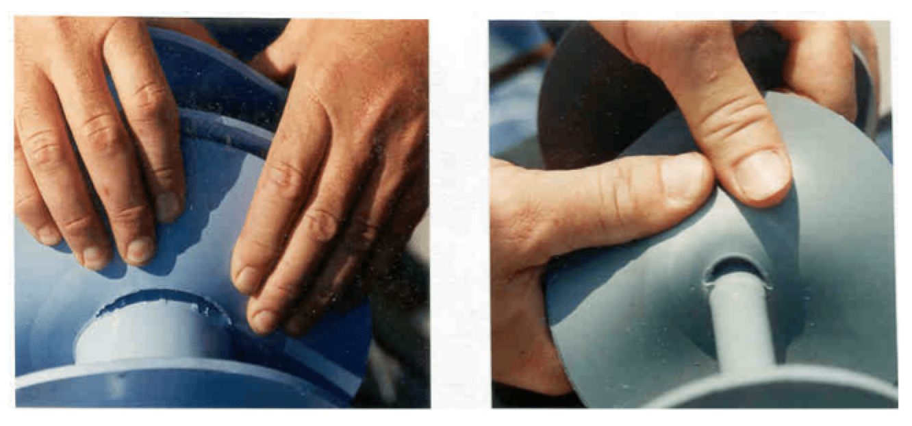
De-bonding of Sheds
De-bonding of sheds is really limited to earlier generation insulators and these days is comparatively rare. While not expected to cause failures, such damaged insulation would not be returned into service. Again, it is essential to ensure that no rod damage or exposure has also occurred.
Leaking Grease
Leakage of grease from inside the insulator core can be considered as compromising an insulator’s electrical integrity and this means it is a matter of time before failure.

Contamination & Damage from Birds & Other Sources
Such contamination will reduce the ability of an insulator to achieve its full electrical insulation properties. Random flashovers can then occur, typically under wetting conditions during early morning or light rains. While most insulation is likely to acquire some level of contamination, in the case of silicone rubber material, an insulator can remain resilient under light to medium contamination.
Mold & Other Biological Attack
This form of contamination will reduce insulator performance, however does not commonly cause failures in service. It does however lead to some deterioration in insulation performance under wetting as well as possible permanent discoloration.
Tracking
Evidence of tracking should be taken seriously as a safety hazard. Often, a high level of tracking may also be audible and can eventually lead to insulator flashover/flashunder. While evidence of tracking may not show up on the insulation itself, inspectors should look for signs on the pole or related cross-arms, i.e. burn etching that finds a path to ground.
Vandalism & Gunshot Damage
Porcelain and glass insulators that are subject to vandalism are readily identifiable whereas in the case of polymeric insulators such damage may be difficult to detect. Any damage to polymeric sheds is usually minor but damage to the rod has the potential to expose the fiberglass core and eventually lead to catastrophic failure.
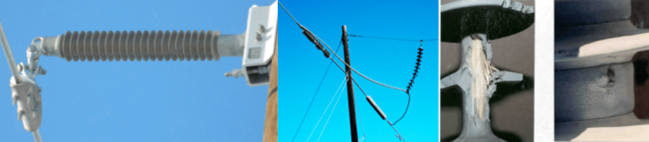
Exposed Core Rod or Seal Failures
Inspectors should consider any and all damage that may result in exposure of the core rod of polymeric insulators as a serious concern that requires immediate replacement. Seal interface failures on end fittings are also often evidence of the insulator nearing end-of-life and are likely due to corona activity, particularly when corona rings have not been employed. Seal interface damage can lead to moisture ingress to the core rod and brittle fracture of the rod if left unchecked.
Overload
It will be rare in the field to see signs of overloading of insulation as typically inspection occur during everyday conditions whereas insulators are designed to handle maximum worst-case conditions. However, if wood pole interfaces are showing signs of wood crushing, or inclined horizontal insulator posts are loaded nearing horizontal, it may be prudent to call for design reviews. In general, if field observations suggest there may be reason for concern, there is value in completing a design review.
Hydrophobicity Classification
Hydrophobicity refers to the ability of a polymeric insulator material to bead water and resist continuous water filming along its surface. Materials that offer higher hydrophobicity better resist the flow of water solutions that create conductive paths.
Engineering Reviews
Value of Formal Report
Often, with all the effort put into field inspections and condition assessment, there sometimes only limited follow-up that is well documented back in the office. An engineering report should be used to summarize and evaluate all identified issues, concerns and necessary repairs on a line and then create estimates for work expected. This document becomes invaluable both as a planning tool and as a means for justifying or assigning funds and later tracking status of recommended improvements. A well-executed engineering report will help facilitate coordination of any deficiencies found on the line along with prioritizing urgency or impact on reliability that can be expected. The report can also be used to provide insight and identification of issues that may need to be addressed in the future.
Design Reviews
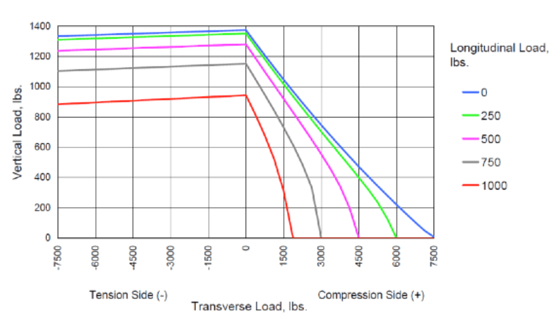
When dealing with historical issues, original designs may have been completed with outdated standards, e.g. acceptable load conditions. Modern software modeling makes it easier and more efficient to check issues such as combined loading criteria for insulators based on actual load. For example, in the case of polymeric post applications, it is common to see ratings such as:
• extraordinary mechanical limits of 60% of SCL (say a maximum of 1 week of insulator lifetime);
• maximum design cantilever loading of 50% of SCL (for perhaps short periods such as 1 minute);
• ordinary loading of 20 to 33%;
• typical combined loading charts, as shown in the example below.
Follow-up Testing
As inspection records and data are reviewed, there may be some indeterminate results that warrant insulation be tested further. This is where it may become prudent to consolidate a group of lines and complete a corona camera inspection of all. Alternatively, it may be best to call for laboratory testing be done on a series of test locations (or possibly of various manufacturers) on a line. These tests could include:
• energized insulator test (e.g. done in the field from a bucket truck on string insulators);
• physical laboratory inspection;
• hydrophobicity measurements;
• degree of contamination, i.e. ESDD;
• electrical testing (basic insulation level at frequency);
• mechanical testing;
• dry arc testing;
• negative impulse voltage test;
• UV accelerated ageing test.
Life Cycle Assessment
An important planning tool can be realized when engineering judgements ‘marry up’ findings from field inspection to expected life expectance curves for various line components. Generally, most utilities have considerable data with respect to vintages of poles in service. However insulator component data is sometimes lost compared to high value asset items such as poles. Like many other components, insulators tend to have a ‘bathtub’ curve representing overall life expectancy. Early in their life, there can be rare manufacturing defects that show up or perhaps, more frequently, damage during handling and installation. Later, during the middle years, frequency of failure diminishes greatly, with typical failures due mainly to external forces or damage (e.g. storms, lightning, birds, vandalism, etc.). During later years, more and more failures start to show up in the form of deterioration, resulting in reduced insulation properties. These lead to earlier onset of outages during certain weather events or cause damage to other components, such as arm burn-offs, etc. These ‘later years’ in the life of insulation can vary due to service conditions such as environment, contamination, level of insulation stress, voltage levels, type of insulation, etc.
Over the years, composite insulators were considered to have life expectancies on the order of 40 years versus porcelain and glass bells that were generally considered to range significantly longer, i.e. from 40 to +60 years. Obviously many factors have come into play with these expected service life ranges. For example, older EPDM type insulation has been found to have a considerably shorter service life than silicone rubber types or those with less effective UV stabilizers, as typical in some early generation polymer insulator designs. Similarly, specific problems arising in grout formulation in some porcelain bell/disc designs has resulted in considerably shorter life spans.
Condition assessments programs should be developed on a cyclic basis, often from 6 to 10 years. This provides for ongoing visibility on adequacy and performance of the facility and specifically of line insulation as it ages.
Data Storage
Line Record Data
Line records and accurate depictions of exactly what is installed in the field can at times be challenging. In this regard, quality of data collection and record keeping will generally dictate the effectiveness and quality of planning decisions. Quality control, reconciling issues and detailed review of the condition assessment data has proven to be a demanding task for many transmission system operators. This is often due to the fact that records to identify insulation and structures have not been tracked in detail. Indeed, without specific knowledge and background on existing insulation systems it is hard to provide detailed assessment of line insulation.
One general recommendation related to insulation system record keeping would be to include catalogue sheets in new-build records. This should also apply to manufacturers and part numbers for material orders that would be kept together with other permanent line records. Tracking insulation can become even more difficult over the years as structure change-outs occur on a line due either to rehabilitation or emergency situations. A rigorous process of maintaining as built records will eventually prove beneficial when the need arises to review overall line data.
Storing Picture Records
Picture records can provide a ‘running window’ into the condition and details for components such as insulators installed on a line, as per the adage: a picture is worth a thousand words. Obvious challenges exist with volume of records and space needed to store data. Having a dated record of pictures for a particular component can also provide useful information when monitoring the progress of any deterioration. Another useful training tool can be to keep an inventory of all past problems as well as inspection findings that have been of concern. This not only helps demonstrate a problem to inspectors but also points to areas where there might be concern in regard to insulation.
Conclusions
Many utilities and industrial transmission system owners find it challenging to make the most productive use possible of assigned maintenance budgets. Moreover, they often also find it difficult to justify requested improvements and funding in a timely manner. There is therefore great benefit in coming up with a simple and practical field approach to inspection and condition assessment of transmission insulators. Such a practical approach does not necessarily eliminate need for further detailed inspection services or testing. However, it does help focus priorities on those facilities having the greatest need for attention. In addition, spending the time to plan and train for inspections and condition assessment of insulation ensures that requirements for longer-term replacement can better be co-ordinated with other facility needs and avoid critical situations.