International standards determine the test requirements to validate the ratings of a power cable and its compliance with operating conditions based on network parameters. Whereas type test sequence validates cable design as representative of a batch or production order, routine and sample tests are applicable to every single length of cable produced in the factory. Application of accessories such as joints to lay extended lengths of cables and connect these to the grid is another key factor guaranteeing system reliability. Such accessories are therefore also subject to a factory type and routine test programs.
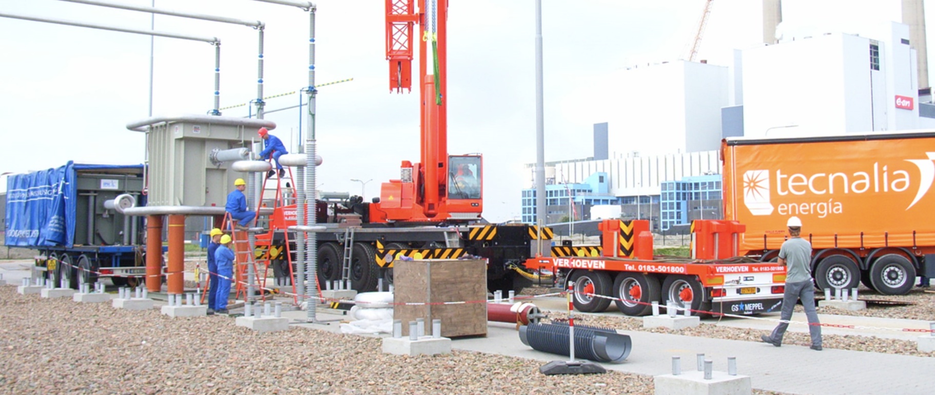
But even when compliance by cables and accessories to requirements in the standards has been proven after production, there is still a long way from factory to installation and operation. This critical interval includes storage, transport, handling, laying and assembly. These activities are mostly performed on-site, sometimes under adverse conditions, and can trigger failures that must immediately be identified and resolved before commissioning of the circuits. So-called after-installation tests are therefore essential to guarantee safe and smooth operation of cables under the rated operating conditions to which they have been designed.
This edited contribution to INMR by Aitor Kortajarena and Imanol Loureiro at Tecnalia Electrical Laboratories in Spain reviews two decades of experience testing HV insulated cables. It also offers some key lessons learned during performance and interpretation of commissioning tests.


After Installation Tests, Standards & Procedures
International standards for high voltage cables, i.e. IEC 60840, IEC 62067, provide an extensive portfolio of factory tests to validate cable and cable system design as well as every single length of cable produced. However, after-installation tests considered in these standards are limited to performance during voltage withstand tests on the main cable and sheath insulation. Partial discharge measurements are recommended, particularly for transmission system voltages, and can be carried out as a complementary technique by agreement between manufacturer and purchaser.
Departing from IEC standards, country legislation and specifications by utilities sometimes go further in the test sequence and might include an extended portfolio of tests, e.g.:
Off-Line Tests & Verifications
• Verification of phase sequence;
• Measurement of resistance of conductor;
• Measurement of resistance of screen;
• DC withstand test of sheath;
• Measurement of capacitance of main insulation;
• Measurement of power factor – tan delta – of cable insulation;
• AC withstand test of main insulation;
• Partial discharge (PD) measurements on accessories, e.g. joints and terminations;
• Verification of ground system at link boxes: SVLs, contact resistance, etc.;
• Measurement of line impedance.
Online Tests
• Partial discharge measurements on accessories such as joints and terminations.

Maintenance & Remaining Life Assessment
Once insulated power cables have been installed and commissioned, follow-up condition assessment of the insulation and components of the circuit become the responsibility of the utility or user. In some countries, legislation requires actions and periodic recordings – typically every 3 years – to verify that the circuit remains in good operating condition. In Spain, for example, it is not usual to extend commissioning tests to diagnostics and maintenance tests, probably due to their high cost as well as unavailability of the circuit for such testing. Large industrial plants sometimes include these tests on main high voltage cables during outage periods while others opt for online PD measurement as an alternative.
Utilities present a maintenance program for their whole T&D infrastructure to regulatory authorities, which exempts them from periodic testing or mitigating scope of the tests. This maintenance program should conveniently include measurement of tan delta since the initial test performed upon commissioning is only a reference to monitor a trend along the cable’s entire service life.
Onsite tests and further inspections can also be used to assess the condition of the installation from the electrical, thermal, and mechanical points of view. Such condition assessment can be used to:
• prevent failures and outages;
• identify weak assemblies and components;
• stock up on spare parts to replace critical components;
• start up a plan for life extension of the cable system.
For example, Tecnalia has been involved in life assessment of high voltage cables at a hydropower plant in Colombia. This included commissioning tests and further testing and verification along the cable route involving:
• Measurement of screen induced currents during normal operation;
• Thermographic measurements;
• Inspection of the entire route, covering fittings, clamps, bending, oil leaks and water ingress.
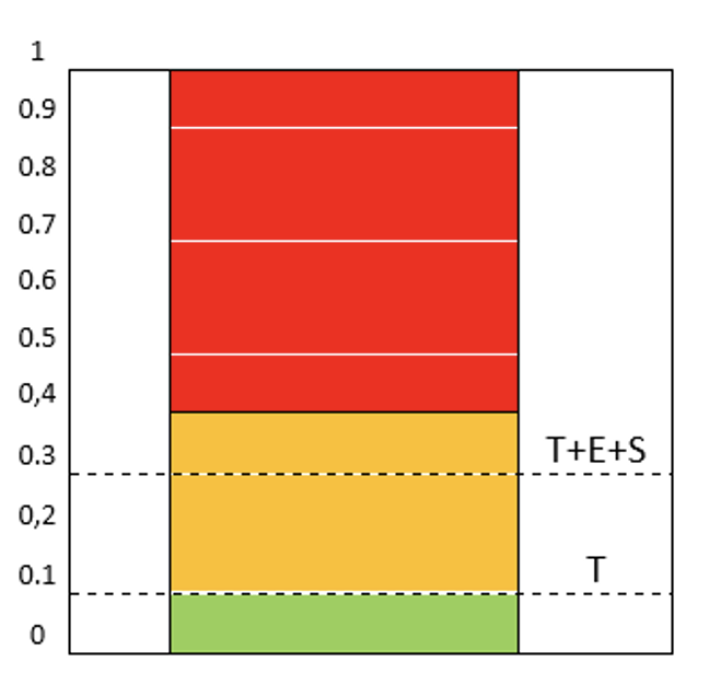
The methodology applied in this work was based on CIGRÉ TB 358, which establishes a traffic light pattern (green, orange, red) to approach the remaining life of a cable system from the technical, economic and strategic points of view.

Failure Statistics
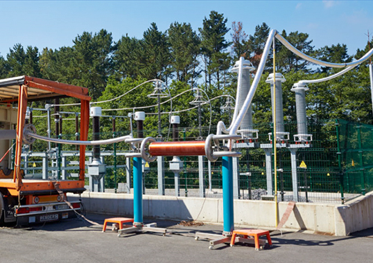
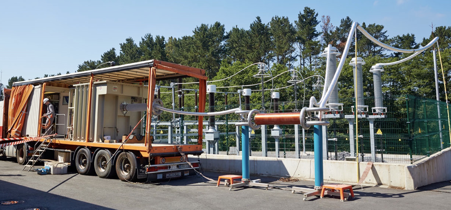
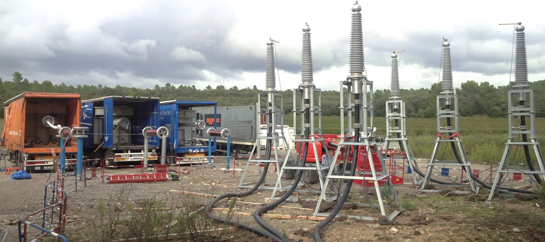
Tecnalia Electrical Labs has been involved since 2005 in commissioning tests of power cables ranging from 36/66 kV to 220/400 kV. HV tests have been performed using a variable frequency resonant unit rated 260 kV, 83 A as power source and supplying a sine wave of frequency range between 20 and 300 Hz in accordance with requirements of the standards. For long lengths, particularly submarine cables, a lower frequency range up to 10 Hz, as per CIGRÉ TB 490, can be acceptable to optimize number of units and accessory equipment required for these tests.
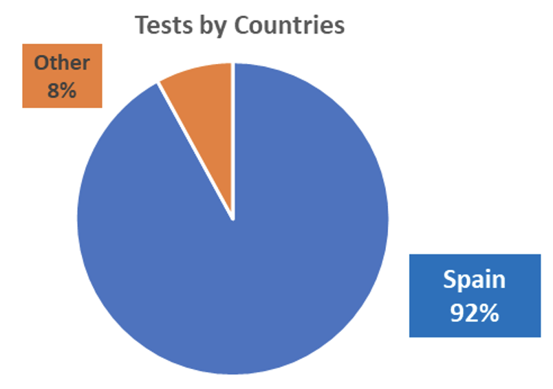
Commissioning tests have been performed mostly but not entirely in Spain, being the test scope based on the requirements of each country, utility or end client. In every case, condition assessment of sheath insulation and of main insulation, including PD measurement, has always been the minimum requirement.
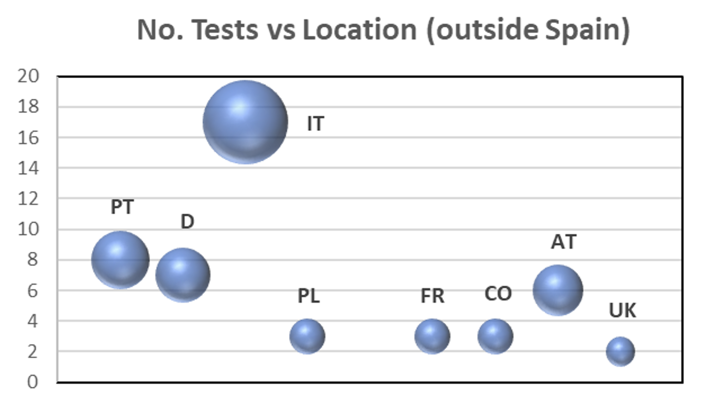
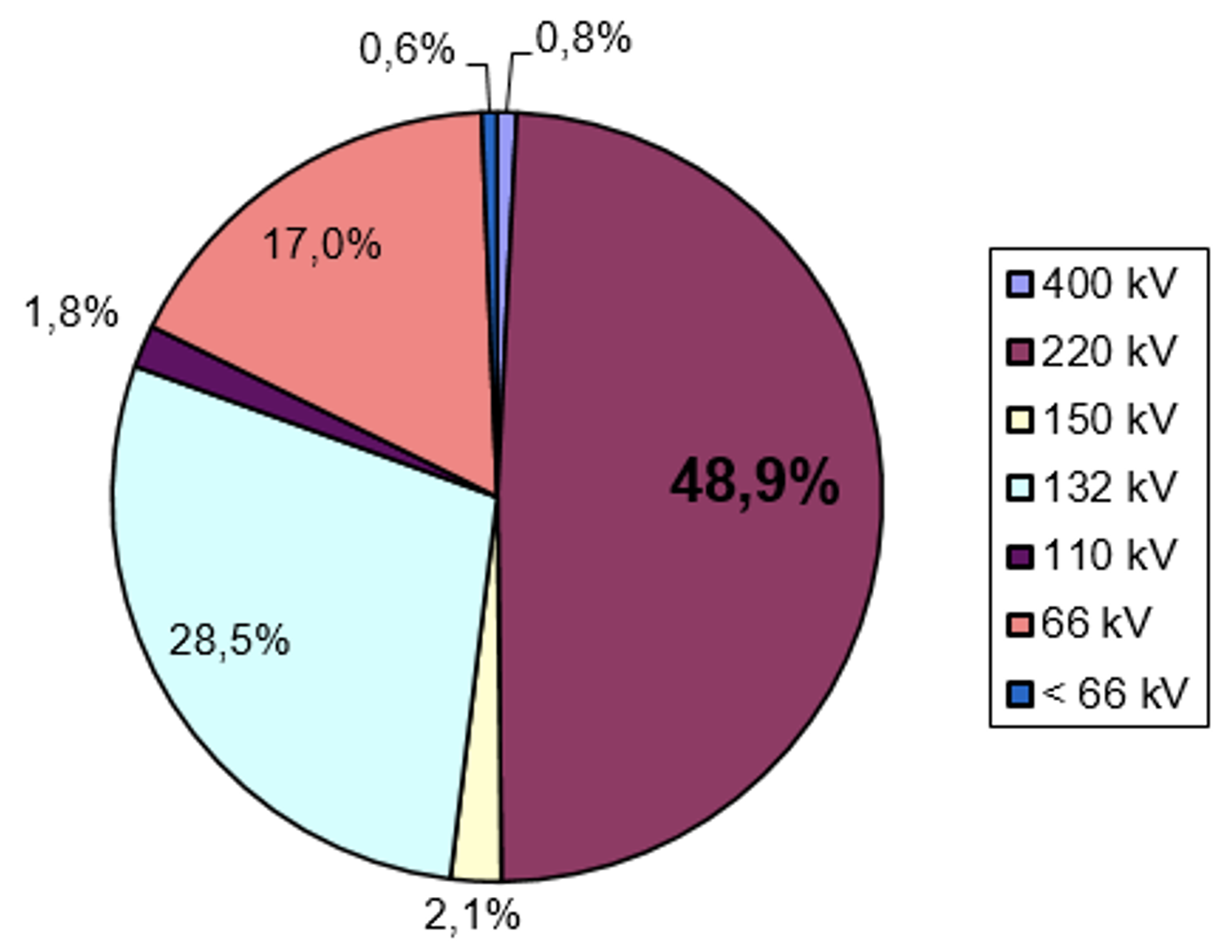
The following data correspond to a population of over 800 three-phase circuits of XLPE power cables rated from 36/66 kV to 220/400 kV (Note: Special tests performed at long lengths of 26/45 kV and ±320 kV DC cables are not included in these statistics).
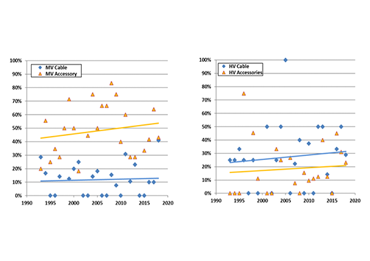
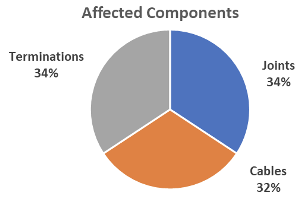
A rate of 4.5% of all circuits tested failed in some way during initial commissioning testing. A non-compliant result in this regard was considered as a failed test, regardless of severity or impact of failure. The following charts indicate failure rate for each component of the cable system. There is a balance between cable, joints and terminations in terms of failure rate if considering individual circuits (i.e. 3 cables, 6 terminations and a variable number of joints depending on total cable length).
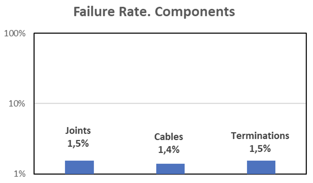

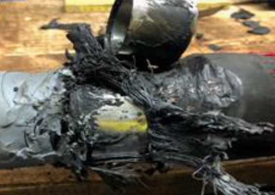
Failures in cables are more often due to sheath problems and relatively rarely to the main insulation. Joints are usually the weakest component of cable systems where sheath problems occur, with PDs detected due to improper assembly. This is more common at voltage levels of 66 kV where such operations are less strictly controlled and tracked. Breakdown of insulation at joints is also relatively common.
Oil-filled terminations can produce PDs if the quality of oil or filling is not the best, resulting in bubbles. In most cases, this can easily be resolved by replacing and/or re-filling. Some new designs of dry-type terminations have also caused PD problems though, in general, dry technology has offered superior performance at higher voltages.
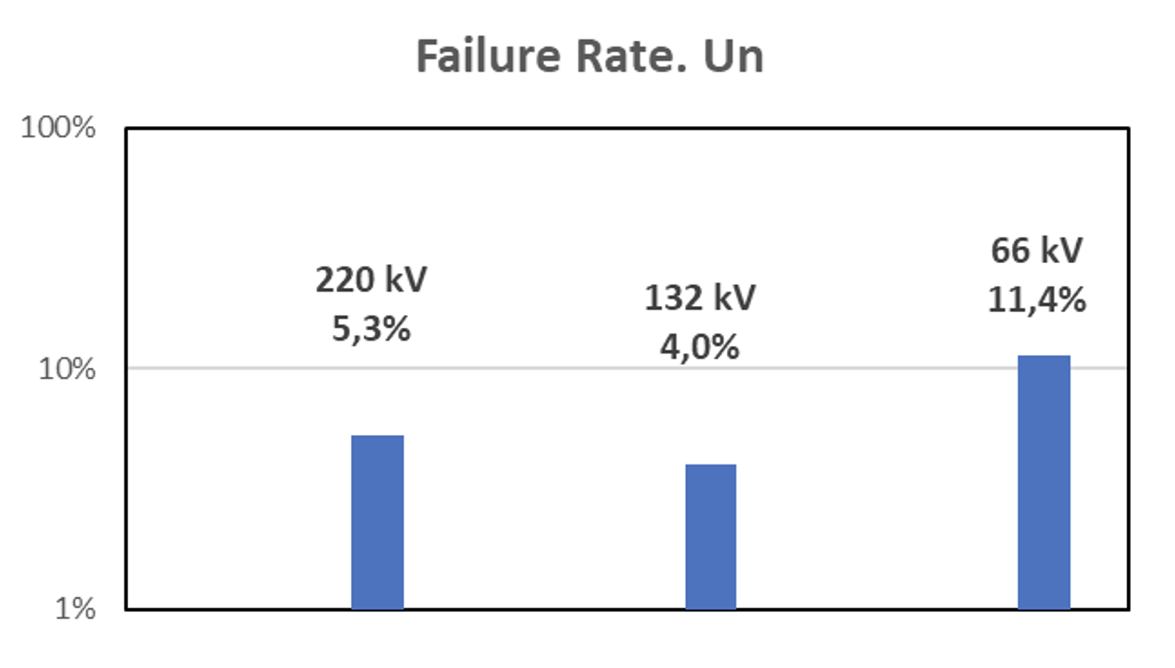
Regarding the voltage test of those circuits that failed during testing, the following chart shows highest incidence at 66 kV. As discussed, this is probably due to less strict supervision over assembly of accessories, apparently regarded as less critical due to lower electric field in service and lower cost for replacement.
Finally, in terms of cable insulation system, a higher failure rate applies to the main insulation, affecting 3.1% of circuits tested. Among these failures, about half were due to breakdown and about half to early detection of PDs.
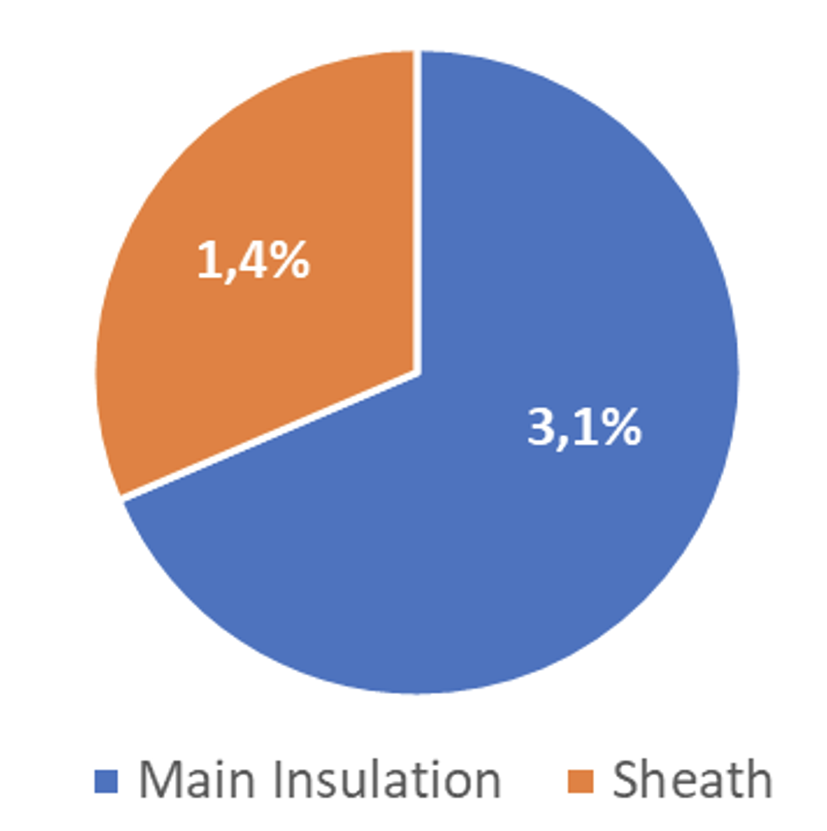
In fact, actual sheath failure rate is likely significantly higher than shown above since not all such failures are detected and resolved. The real rate is probably roughly three times higher than that in the chart.

Lessons from Performing & Interpreting Test Results
As discussed, the scope of commissioning testing is defined by the final end-user according to local legislation, international standards and particular specifications. However, some tests are mandatory in all cases and focus on assessment of insulation condition, i.e.:
• Voltage withstand test on sheath with DC;
• Voltage withstand test on main insulation with AC;
• PD measurements.
1. Voltage Withstand Test on Sheath
A graphite or semi-conducting coating is applied to the sheath’s external surface to provide a continuous potential for the test so that the entire sheath insulation can be tested to identify possible damage during installation. However, this coating can also lead to incorrect measurements at the accessories where the screen is in close contact with the semi-conductive coating of the external sheath. For this reason, it is necessary to discontinue application of the coating along roughly 50 cm in order to perform the sheath test between the unearthed screen and the sheath. The extension cables of the screens are used only at link boxes and usually have lower insulation level. They can also have a semi-conductive coating and occasionally cause similar problems during the test.
In addition to a sheath test of the whole length of cable in each phase (once cross-bonding connections have been replaced by direct connections), this test is also carried out at the coaxial cables that connect the screens to the cross-bonding link boxes. This is usually implemented for lengths of a few kilometers to reduce induced current on the metallic screen. A DC voltage test is performed as well between inner and outer conductor of the coaxial cable.
Implementation of surface manholes to host the link boxes external to underground joint bays avoids the need to access confined spaces and facilitates the screen sectioning test.
2. Voltage Withstand Test on Main Insulation
This test is performed by application of an AC high voltage between the main insulation and the grounded screen. The voltage level is defined either by IEC standards or any particular specifications that may apply, usually falling between 2 times Uo (36/66 kV) and 1.18 times Uo (220/400 kV). Exceeding a test voltage of 260 kV requires use of at least two resonant units or one additional insulated reactor. Test duration is typically 60 minutes. Again, alternatives to this test duration may also apply.
Quality factor of the system shall be checked as well. Values under 100 can be due to corona sources and/or faulty set-up of the grounding system. In cases of long lengths, application of voltage at both ends of the circuit or reactive compensation at the opposite end can also contribute to an improved quality factor.
The main precautions to be undertaken during this test are to isolate the ends of the cable under test from the rest of the switchgear, which shall be connected in service as well as to keep the insulation distance to withstand the test voltage. That will depend on the insulation, whether air, gas or oil. Care shall be taken with the voltage transformers at the GIS to prevent any damage due to the high frequency transient voltages during the test. VTs should therefore have been previously removed.
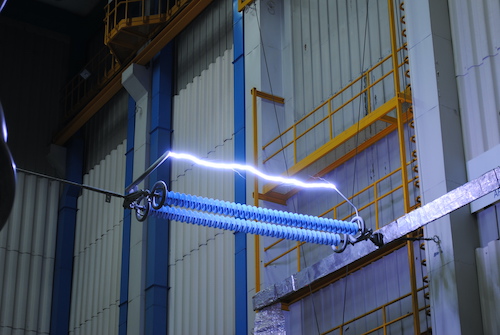
3. PD Measurement (Offline)
A voltage withstand test can never fully replace PD measurement since the former is a pass/fail test. The latter, by contrast, is a diagnostic test that provides extensive information on insulation condition based on phase-resolved PD patterns, noise rejection, signal classification as well as inception and extinction voltages.
One typical question is when best to perform PD measurement, i.e. before, during or after the voltage withstand test. Any option can be justified and all are actually included in the specifications of many end users.
The goal of performing PD measurements before the voltage test is to determine the actual condition of each component of the cable system prior to the withstand test. This allows detecting any possible failure or assembly defects that could show early PD activity at lower voltages. Such early PD detection can prevent breakdown and facilitate inspection and possible remedial action on the affected component.
PD measurements can also be performed during the withstand voltage test, even when there may be mismatch of test voltage levels. PD measurements are usually performed at 1.5 Uo for each accessory while the withstand voltage test goes from 2 Uo (66 kV) to 1.7 Uo (132 kV) and 1.4 Uo (220 kV). Another important point is that, in cases of long lengths with significant number of accessories, many PD sensors and measuring units are required, as for online measurements. Thus, this option is useful only in limited cases.
Finally, PD measurements can be performed at the end of the withstand voltage test on each accessory. Some theories consider that the voltage test can stress the cable insulation and that the most realistic view of PD mapping should therefore be obtained once all commissioning tests have been completed and prior to connection to the network.
Another issue when performing PD measurements in long lengths is to reduce stress time as much as possible, considering that each accessory should be stressed to 1.5 Uo to get the appropriate PD pattern. Time required to perform PD measurements in case of a large number of joints can be considerably longer than required for the voltage withstand test. In such cases, test voltage for the PD measurements should always be lower than for the withstand voltage test.
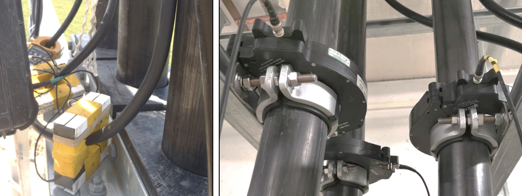
When measuring PDs, attention must also be paid to the complete test set-up. The following points in particular are recommended:
• Place local HFCT sensors coupled at the screen connections of the link boxes for each accessory. This will optimize the signal-to-noise ratio. Alternative large diameter HFCTs embracing the power cable can be used as well.
• Tune the frequency range of the measuring unit to obtain the best possible ratio between signal and noise, always in the range of MHz where PD activity is highest.
• Use flexible tubes for the high voltage connections with large diameter and corona rings, avoiding sharp edges to prevent any corona disturbances.
• Connect all earthing bands and meshes to a single point as a star connection at the voltage supply side.
• Earth the link boxes only at the terminations to capture the PDs coming from each accessory at the local HFCT sensor and to prevent any other pathway to ground. SVLs removed.
• Avoid proximity to lines in operation, particularly at high voltages. If no outage is possible, identify the induced noise signal to remove it from the PD pattern. Such signals are more likely to be detected when measuring PDs at outdoor terminations.
• Avoid any metallic floating elements in proximity of the test set-up.
• Avoid measuring under certain weather conditions such as rain, dew or wind, which can lead to confusing signals.
• Install the high voltage filter with a blocking impedance at the exit from the resonant unit to block disturbance propagation between power source and measuring units.
• Avoid or mitigate coupling of noise signals coming from electronics at substations.
• Check level and pressure of insulating fluids (i.e. oil and SF6) at terminations since air gaps can produce PD signals.
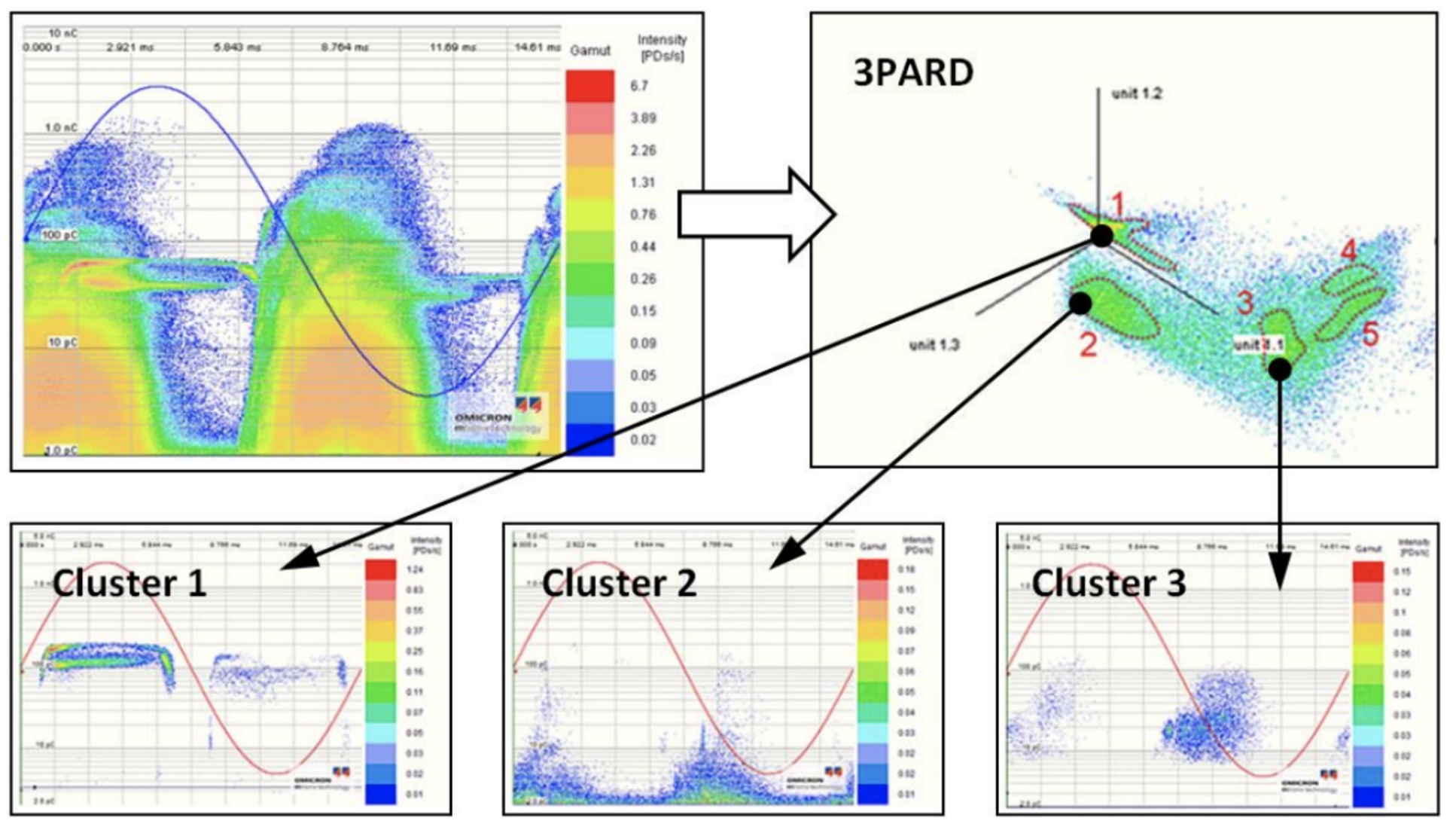
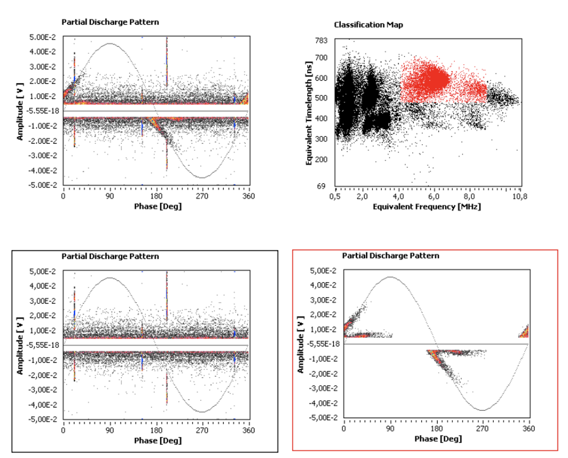
Hardware and software technologies contribute to clearly differentiating potential PD signals produced at the cable system insulation from high frequency disturbances not related to the test object. SW techniques can include TF maps (equivalent time-length and frequency bandwidth), 3PARD plots (three-phase filtering tool) for phenomena separation and noise rejection, as well as others.
The only acceptable result for PD measurement is absence of PD signals coming from the cable or accessories over background noise, once all necessary filters have been applied to exclude external coupled signals.
Location of PD sources can be determined using local sensors and Time Domain Reflectometry (TDR) techniques based on travelling times of high frequency signals along the cable between source and measurement point.
Verification of Phase Sequence
This test is particularly relevant with long lengths where the possibility of connecting different phases at the joints is higher. A phase crossing shall cause problems during commissioning in the system operation and protection system.
Measurement of Resistance of Conductor
This test is performed to guarantee that the deviation with respect to the expected value of resistance supplied by the manufacturer or from calculations made from the conductor material and cross-section do not exceed a certain percentage, commonly 10%. This is particularly relevant when joints are installed to verify quality of the connectors. However, it is unlikely to see measurements that may exceed these limits unless there is some change in the cable design actually installed with respect to the original project.

Measurement of Resistance of Screen
This test is performed to guarantee that the deviation with respect to the expected value of the resistance supplied by the manufacturer or from calculations made from the screen material and its cross-section does not exceed a certain percentage, commonly 10%.
These measurements are usually more sensitive than those at the conductor since some wires, in case of wire screen, might be broken during installation. It is however unlikely to detect high values of impedance that might detect this problem. It should be noted that some extension LV or MV cables commonly used to connect the screen to the link boxes might influence total measurement of resistance.
Measurement of Capacitance
This test is performed to prove that the deviation with respect to the expected value of capacitance supplied by the manufacturer does not exceed a limited percentage. It can be used as an indirect measurement of total length of each cable phase and necessary to determine the power required for the test and the test frequency.
Measurement of Tan Delta
Measurement of tan delta or power factor is well known as part of the electrical type tests performed in the laboratory to qualify a cable. According to the standards, it is performed at rated voltage, Uo, and power frequency 50/60 Hz.
Measurement of tan delta on-site is more controversial and debatable for a variety of reasons. On the one hand, this diagnostic technique is more related to overall condition of the entire cable system, i.e. it is more related to ageing condition over the service life than to existence of weak points or local defects during commissioning. Therefore, the real interest for this measurement comes from Maintenance Departments and it can prove useful to monitor trends during periodic measurements at the same condition over the life of the cable.
On-site measurements at Uo and 50/60 Hz are extremely difficult to perform since the variable frequency resonant units used for these tests cannot provide the power required out of the resonant frequency of the system. Use and transport of a high voltage SF6 filled standard capacitor to take high accuracy measurements (in the range of 10-4) is another issue. As a result, measurements are usually taken at a power frequency of 50/60 Hz, as at the factory, even when voltage applied is clearly less than Uo.

Verification of Link Boxes
Usual checks include:
• Contact resistance
High values can lead to hot spots in service. A limit of 10 µΩ is usually considered as acceptable.
• Equipotential cable
Necessary to keep an equipotential earth grid for the whole circuit, particularly for long lengths with substations at both ends.
• Sheath voltage limiters (SVLs)
Protection system in case of induced high voltage on the screen under operation. A DC voltage based on the SVL model is applied to verify that the current does not exceed 0.10 mA. SVLs can be installed at one or both ends of the circuit and at cross-bonding boxes.
Line Impedance
This test permits measuring loop impedance that the protection system will see in case of a real fault on the line. Although these impedance values can be obtained by calculation, significant discrepancies between calculations and real measurements are common.
Condition of earth connections is fundamental to obtain good measurements. This is sometimes problematic in the case of transmission structures.
PD Measurement (Online)
Installation tests are performed offline on the test circuit to guarantee good condition of the cable systems and successful connection to the network. In some cases, however, where conditions do not allow use of a resonant unit or any alternative external source to energize the circuit (e.g. lack of access, lack of space, risks to facilities, etc.), a soak test is commonly performed using the network to feed the test circuit under no-load condition for 24 h. It is obvious that this voltage is significantly lower than any value considered in the standards for the withstand voltage test. As such, stress applied and risk of breakdown – even in the case of defects in the insulation – is negligible. Thus, online PD measurement, even when the voltage applied is not sufficiently high, is a far more sensitive technique to detect possible defects in the insulation. These measurements can be taken under no-load conditions and/or under different loads.
To achieve good signal sensitivity, local sensors must be installed. While simple in case of short lengths, this is more complex in case of long lengths where there are significant numbers of joints. This would require a large number of sensors interconnected by fiber optics or any other real time means of communication.
Online PD measurements are also often for maintenance programs in power and industrial plants. There, performing offline tests is to be avoided due to cost and need to schedule an outage of a circuit, which is usually critical for normal operation of the plant.
Conditions for online PD measurements are obviously more complex and the techniques employed are usually more advanced in terms of noise suppression. Moreover, results are not always conclusive. In case of questionable results, new offline measurements are recommended to confirm or discard any abnormalities.
Tests on Long Lengths
Transmission networks are trending toward longer lengths of cables. For example, large renewable plants are usually installed far from existing grids, as is the case for offshore wind farms. Deployment of an interconnected Supergrid links countries and islands using underground and submarine cables. Commissioning tests of long lengths require high power to feed large capacitances at the test voltage while keeping the frequency within acceptable limits. This results in use of several resonant units connected in parallel to increase the power or in series to increase the voltage.
Tecnalia has experience testing long lengths jointly with other partners, including underground and submarine lengths. Examples include the interconnection links between Mallorca-Menorca in the Balearic Islands and between Fuerteventura-Lanzarote in the Canary Islands or country links such as the ElecLink Project between the U.K. and France.
A higher quality factor of the test system may optimize the set-up and means required to test such long lengths of underground and submarine cables. Reactive compensation at the opposite end of the circuit is a good option to optimize quality factor.
Conclusions
Installation of insulated cables for distribution and transmission networks, from MV to EHV, in underground and subsea projects has experienced enormous growth in recent years, propelled by the goal of de-carbonizing electricity systems. New and ambitious projects are being developed as part of interconnected Supergrids between countries and islands, based on deployment of offshore and remotely located renewable plants and their connection to power grids. Underground and submarine circuits are becoming longer, which creates complexity in laying, assembling and jointing operations thus potentially compromising system safety and reliability.
After-installation tests are crucial to guarantee reliable commissioning of new circuits based on insulated cables and significantly reducing probability of failure of any of their components during their normal service life. This will help prevent major outages that can severely impact network stability given the difficulty in locating and repairing any failures along an underground and/or subsea circuit. Even when rate of failures detected during such commissioning tests is relatively low (but certainly not negligible), any failure in service will have great impact on a system and cause high economic losses.
Commissioning tests should be accompanied by maintenance programs based on monitoring condition of assets as well as operating a circuit under controlled ratings of voltage, current and load.
References
[1] “Power cables with extruded insulation and their accessories for rated voltages above 30 kV (Um = 36 kV) up to 150 kV (Um = 170 kV) – Tests methods and requirements” IEC 60840.
[2] “Power cables with extruded insulation and their accessories for rated voltages above 150 kV (Um = 170 kV) up to 500 kV (Um = 550 kV) – Tests methods and requirements” IEC 62067.
[3] “Remaining Life Management of Existing AC Underground Lines” CIGRÉ TB-358, October 2008.
[4] “Recommendations for Testing of Long AC Submarine Cables with Extruded Insulation for
System Voltage above 30 (36) to 500 (550) kV” CIGRÉ TB-490, February 2012.
[5] “Maintenance for HV Cables and Accessories” CIGRÉ TB-279, October 2005.
[6] “Upgrading and Uprating of Existing Cable Systems” CIGRÉ TB-606, January 2015.
[7] “Strategic Asset Management of Power Networks” IEC White Paper, 2015.
[8] A. Kortajarena, “Ensayos de puesta en servicio de cables de alta tensión”. Seminario Internacional sobre ensayos eléctricos SISEE. Cali, Colombia, October 2016.