Engineers responsible for specifying insulators for new overhead line projects face a choice among three insulator technologies: porcelain, toughened glass and composite. The former two are sometimes grouped together as ‘ceramic’ while the third has been called ‘non-ceramic’. Often, composite insulators are also known as ‘polymer’, to reflect that housings are made of a polymeric material. At times, glass and porcelain have been referred to as ‘conventional’ or ‘classic’ insulator technologies while composite insulator technology has been called ‘unconventional’ or ‘synthetic’. It can be confusing.
Although each technology has a solid track record based on decades of successful applications across the globe, each also has notable examples of failure. In all cases, investigation has demonstrated that these failures were linked to deficiencies within the technology instead of to deficiencies inherent to the technology.
In 2005, the late Claude de Tourreil, one of the most trusted experts in the field, remarked: “The performance of line insulators depends on a number of factors – irrespective of their type. Firstly, they must be correctly designed and manufactured. Then, they must be properly selected for the intended service environment as well as handled and installed according to recommended practice. Later, during service, the utility must be able to inspect the insulators and decide if they remain in good condition.”
Unfortunately, the industry that supplies electrical insulators has never reached consensus on which technology performs best across all applications. Moreover, since most insulator suppliers manufacture only one technology, it is understandable that competition is sometimes based as much on technology as on quality and price.


Some manufacturers have even suggested that selecting the ‘wrong’ insulator technology can doom a line to future problems. Users can find themselves receiving mixed messages about what is really going on in the field and decision-making can become based as much on fear as on facts.

Insulator failure can be linked to a variety of causes.
Poor Manufacturing & Quality Control Processes
This can result in some batches of insulators that contain inherent defects in materials or construction.
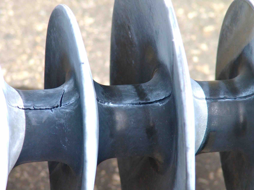
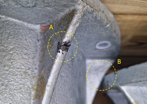
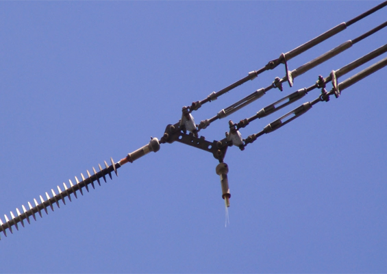
The composite insulator in Fig. 3 was removed years ago from a trial installation on a transmission line in western Canada. This experience made the utility hesitant to again select composite insulators in the future. However, the damage detected during inspection was traced to improper de-moulding by the manufacturer, which created a structural weakness at the seam. Here was a case not of insulator technology failure but of manufacturing failure.
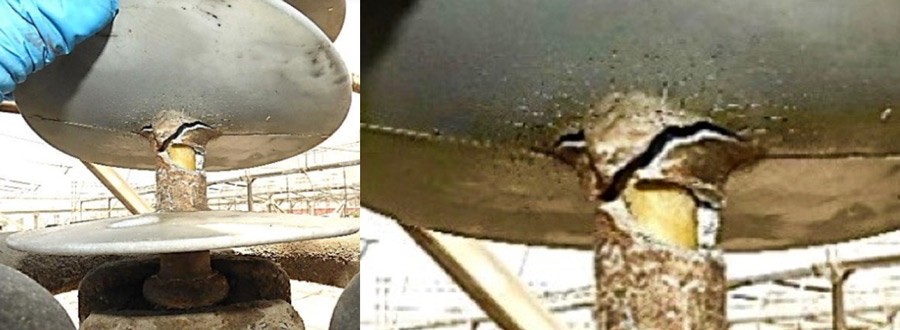
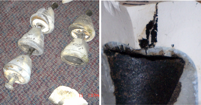
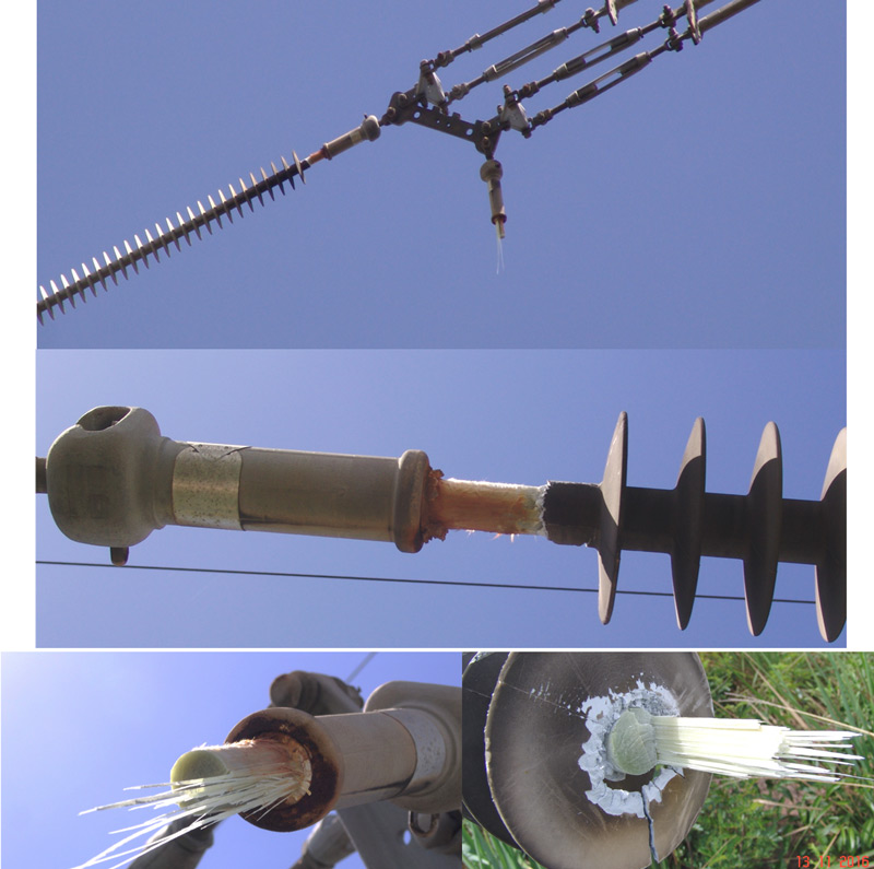
The composite insulator in Fig. 4 degraded to failure after only 9 years service on a 220 kV coastal line in Peru. Based on this, the country’s TSO concluded that composite insulators may not be a suitable technology for this type of service environment. Yet it is clear from the photo of one the failed units that the rod and housing have de-bonded. Investigations in Europe have determined that the root cause of many failures of improperly manufactured composite insulators is poor adhesion at the critical interface between FRP core rod and silicone rubber housing.
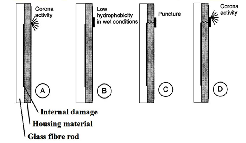

The mechanism of what happens in service is thought to be that any air-filled space between the rod and silicone becomes filled by moisture due to diffusion through the rubber or due to poor sealing. With time, this initiates internal partial discharges that lead to a partially conductive layer between rod and housing or within the rod. The HV potential is then transported from the HV fitting along the insulator. The short-circuited path increases electric stress and this initiates corona which locally degrades hydrophobicity. Over time, this creates erosion or punctures through the housing.
If this failure mode is typical of the other failures on these lines, this may be another instance of failure of quality control by the manufacturer rather than failure of composite insulator technology for the application.
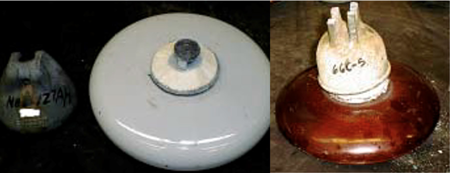
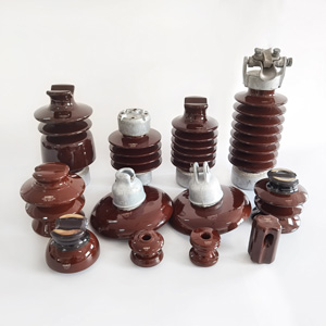
Past research conducted at Arizona State University studied a variety of porcelain disc insulators from different manufacturers removed from 66 kV and 115 kV systems in high contamination service areas. In some cases, there was no evidence of degradation in mechanical strength, even after 50 years. But in other cases, mechanical strength had dropped significantly after only 10 years of service.
Similarly, low quality porcelain insulators can develop internal conduction paths during service, which will eventually cause puncture. Development of such channels has been found to be linked largely to materials, microstructure and interface details. In other words, porcelain insulator technology can be subject to ageing and the degree of such ageing will depend on specific formulation and manufacturing details. One cannot conclude that selecting porcelain string insulator technology in itself will guarantee long service life.

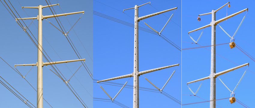
Unsuitable Design for Intended Service Environment
If insulator design is not suitable for the intended service environment, the result can be insulators that are not able to withstand imposed service stresses. This can be due, for example, to insufficient information on the pollution exposure of insulators at the time a line is designed and constructed.
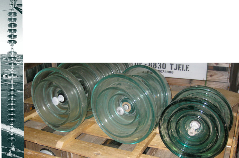
to better cope with high pollution service environment that caused high shatter rate (left).
Fig. 8 shows an example of the high rate of shattered glass insulators observed during the 1980s on suspension strings on the poles of a coastal ±350 kV DC line near the northern tip of Denmark’s Jutland Peninsula. In 1988, in an attempt to resolve this problem, it was decided to re-insulate all suspension towers with a second generation design offering higher quality glass, greater mechanical strength from more robust pins and also a zinc sleeve to reduce corrosion caused by high leakage currents.
In 2002, when the problem of high shatter rate was still not resolved, all insulators on suspension towers were again replaced, this time with a third generation glass insulator design that offered a larger zinc sleeve as well as a semi-conducting material over the cement to better protect against corrosion. Another significant change was a factory installed RTV silicone coating to ensure longer service life. Here was a case of need for improvements in product design for the service environment rather than failure of the insulator technology.
Improper Storage & Handling
This can be a factor for all types of insulators but especially so in the case of composite types, which risk being degraded or permanently damaged if not stored and handled properly. Unfortunately, when first introduced on a commercial scale in the 1980s and 90s, composite insulators were sometimes promoted as indestructible. This resulted in years needed to re-educate users that, if anything, the opposite is true.
Unsuitable Assembly Design or Improper Installation
This is particularly important for composite insulator technology where an improperly designed field grading device or absence of any grading hardware by omission can both lead to premature degradation and eventual mechanical failure.
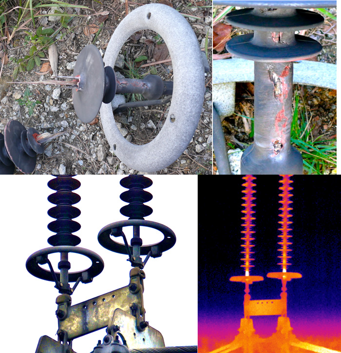

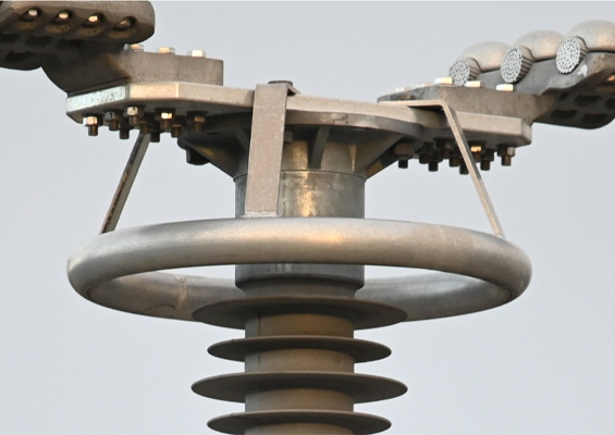
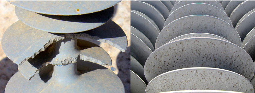
In 2011, a number of mechanical failures were reported in a polluted area of southern China, one of which involved a composite I-string insulator on a 500 kV line (see Fig. 10). Subsequent investigation revealed that this was not the result of manufacturing defects but rather severe erosion of the silicone sheath due to corona discharges. This allowed moisture and acids to penetrate into the core and erode the rod material. A total of more than 600 such strings were examined over the following months as part of a systematic inspection program using a handheld infrared camera.
This revealed that some 85 strings were ‘running hot’, i.e. had abnormally high temperatures near their live ends versus ambient. In the end, several dozen strings were replaced with insulators having the same basic shed geometry and creepage as the failed unit but featuring an improved design of corona ring. While the original insulators were equipped with rings having a concave lower surface, rings on replacement insulators had convex upper and lower surfaces. This example demonstrated that effectively grading electric field near the live end is a critical requirement for composite insulators operating on high voltage lines – especially so in areas with elevated pollution levels and frequent wetting events.
In late 2016, a mechanical failure was reported involving a composite insulator operating for 14 years on a 400 kV overhead transmission line in Venezuela. Investigation revealed that a brittle fracture occurred in the FRP core rod as a consequence of omitting to install corona rings during construction. This experience highlighted the importance of ensuring such rings are used, especially at this voltage level, and also the need for careful visual inspection by lines workers and technical staff.

Conclusions
Failures of line insulators carry serious consequences and costs. Everything possible must be done to ensure such risk is kept as low as possible. This includes studying the service environment where insulators will operate, ensuring that stringent quality control processes are adhered to in the factory and conducting rigorous testing according to the latest standards.
Users of insulators should not link individual failures of any one type of insulator from a specific manufacturer with some inherent deficiency in that technology. The facts do not support such a conclusion.
The marketplace offers many examples of high quality and low-quality insulators within every technology. Performance in service is determined by product quality and not by technology. Suggesting that one technology, irrespective of quality, will always perform best is simply not correct.
Each insulator technology can offer a viable solution for a line application. If properly designed, manufactured and tested for the intended service environment, each can offer a realistic alternative. Key differences are in acquisition cost, expected service life and maintenance needs for that specific application.
It is therefore the responsibility of users to decide which insulator technology best meets their requirements in terms of performance and total life cycle costs. No single technology is inherently superior across every possible application.