The advent of composite insulators began during the 1950s, first in the U.S. and soon after in Germany and France. User acceptance was slow and these products went through ‘teething’ problems common to most innovations. Moreover, initial pricing made them too costly for broad application.
But all this changed by the mid to late 1990s and today these types of insulators account for over half the world market. Competition and production volumes have soared and, with this, acquisition costs have typically become less than for porcelain and glass counterparts.
One of earliest applications for composite insulators was as insulating cross-arms, which are indispensable for design of compact lines and so-called aesthetic towers. The former, in particular, are rapidly gaining ground as an alternative to building traditional lines due to higher public acceptance. Moreover, composite insulators play a growing role in cases of line uprating to increase power transfer capacity of existing lines.
This edited past contribution to INMR by Dr. Konstantin O. Papailiou, current CIGRE President, explained the necessary properties of composite insulators as well as examples of such applications.
Compact lines were first developed in the 1970s but only started to become popular during the late 1990s due to rapid growth in the availability of composite insulators. Insulated cross-arms, which are indispensable for installation of a compact line, are loaded primarily by compression, which means that they are subjected to relatively large deformations. These deformations can better be sustained by composite materials than by conventional porcelain and glass insulators. Specifically, the following key properties of composite insulators are advantageous for application in insulated cross-arms: high bending strength; elastic limit in the region of ultimate strength; high ultimate strain; and non-brittle behavior


Options for Line Compaction
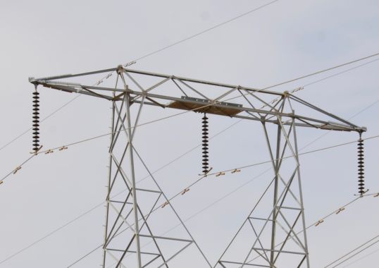
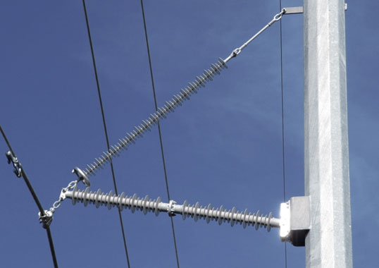
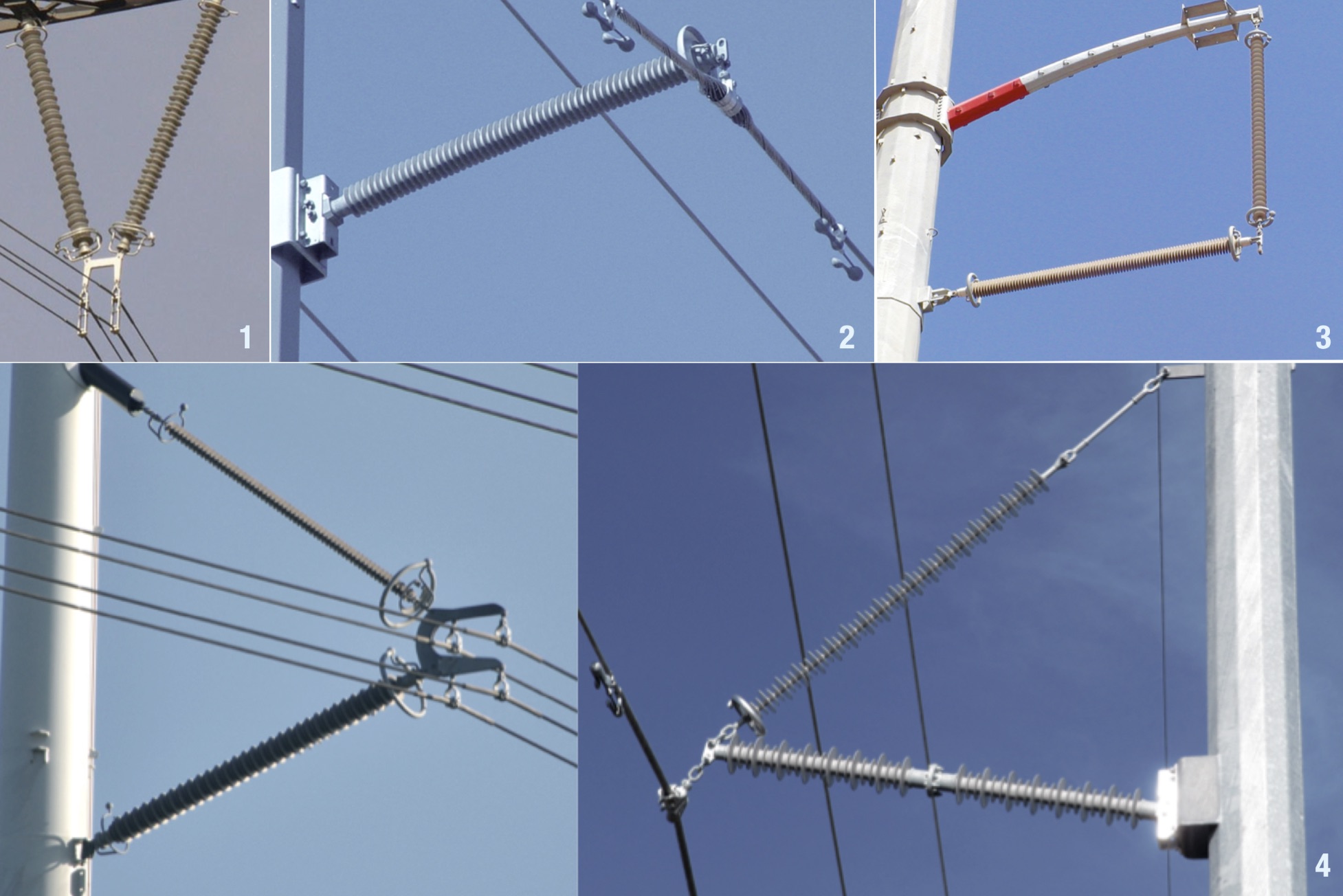
The basic idea behind line compaction is to suppress horizontal movement of the classical suspension string. This way, line supports can become more slender and, at the same time, the right-of-way dimensions needed are reduced. Over time, four different insulator arrangements have come to be used for line compaction: V-strings; horizontal posts; suspended posts; and insulated cross-arms. These four arrangements are shown in Figs. 1 to 4.
Mechanical Design
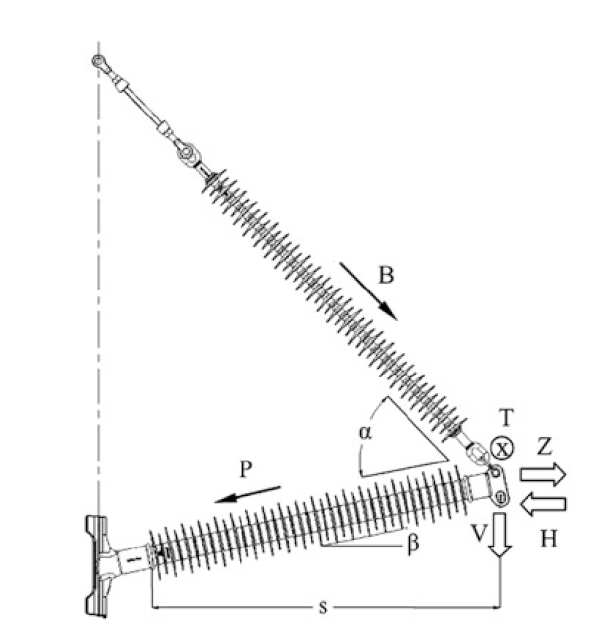
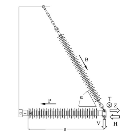
Fig. 5 shows the loads that act on an insulated cross-arm. These are:
• vertical loads, V, from the conductor and from ice, if present;
• horizontal loads, H, from wind and, in the case of light-angle supports, from angular pull; and
• longitudinal loads, T, possibly from non-uniform conductor tension in adjacent spans or from a conductor failure – a rare exceptional load.
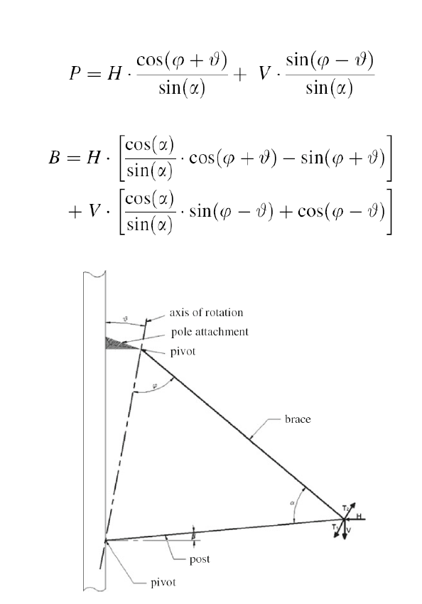
The vertical loads are taken up largely by the brace, depending on the angle, between the brace and post. By contrast, horizontal loads acting in compression, load the post in buckling. The insulator forces, i.e. the compression force, P, on the post and tensile force, B, on the brace are calculated, assuming T = 0, using the following formulas:

Rigid Connection
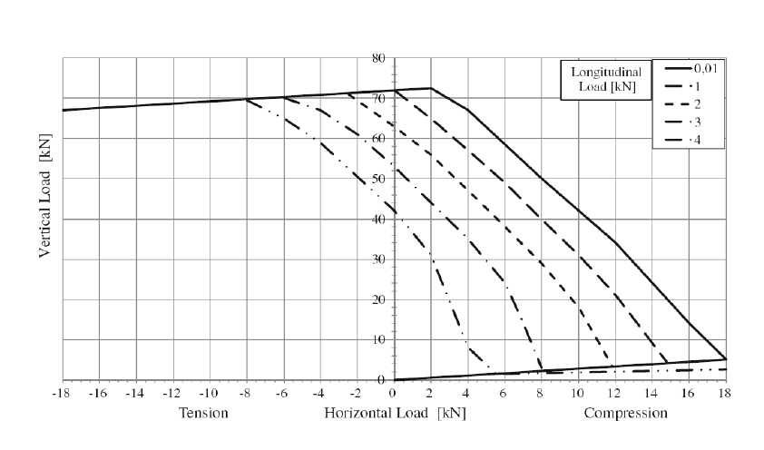
For voltages up to 245 kV, the post is often rigidly connected to the support (as in Fig. 6). CIGRE WG 22-03 used commercial finite element software to calculate the loading diagram, also called the application curve, for a 63 mm post of 2000 mm length with inclination angle to horizontal of 15° (see Fig. 8). Coupling angle of the 16 mm brace to tower was 45°, this brace being assumed to pivot at either end.
The load on the brace should not be negative (compression) so as to prevent buckling of the brace that would lead to contact between the metal fittings of the two insulators. With a horizontal angle of the post insulator of 15°, as used here, this condition leads to the inequality: V > H tan 15°. In this diagram, the lower straight line corresponds to the equality V = H tan 15°, i.e. the brace is not loaded along this line or, in other words, the insulated cross-arm should not ‘work’ below this line. The upper straight line in the diagram extends parallel to the lower straight line and corresponds to maximum allowable tensile load of the brace. It is good practice to use a so-called fail-safe base for the post, which will be plastically deform in case of overload thus protecting the more sensitive – and more expensive – post.

Pivoted Connection
This is the most commonly used arrangement, particularly for higher voltages, since it has a high level of mechanical strength and is also fault-tolerant in case of transverse loads (see Fig. 8). The composite long rod in the brace is loaded purely in tension and can be easily dimensioned. By contrast, the post is loaded in compression and, since it is articulated at both ends, can be calculated as a Euler beam with maximum tolerable compression load, i.e. the Euler load:
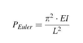
where E is the modulus of elasticity, I the moment of inertia and L the length of the post insulator’s fiberglass core rod.
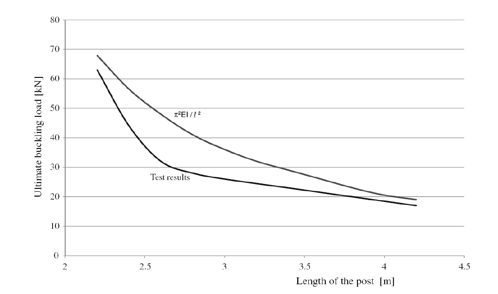
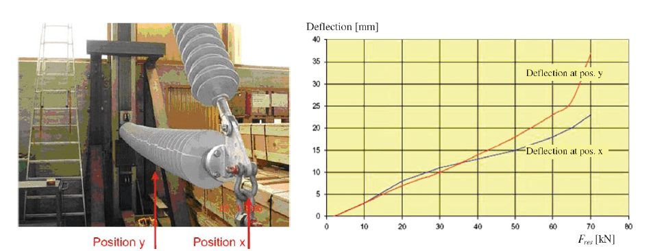
It must be noted, however, that, due to an often-unavoidable eccentric application of compression load, the post insulator is additionally subjected to bending. The negative influence of this eccentricity can be seen in Fig. 9, where results of buckling tests performed on 63 mm diameter rods are plotted versus maximum buckling load given, as described above from the conventional buckling formula. Considerable reduction can be seen in measured failing load compared to theoretical buckling load and this must be considered in design. Since this and other effects, e.g. partial rigidity of the pivots, cannot reliably be modeled, it is recommended that the insulating cross-arm be type tested before putting it into service (see Fig. 10).
Stability Issues
One particular advantage of pivoting insulated cross-arms is their ability to stabilize in the event of sudden conductor movements. Such movements could take place should temporary differential line tension occur at the tip of a cross-arm on an overhead line section consisting of a number of spans. These movements could be caused by gusts of wind, irregular icing, spans of considerably different length (e.g. as in mountainous terrain) and short circuit forces. Particularly in the case of long cross-arms for higher voltages, it may be that cross-arms become de-stabilized, leading to considerable deflections with associated reduction in safety distance between conductor and tower. In extreme cases, the cross-arm could fail mechanically.
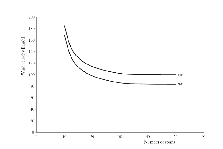
If there are differences in horizontal line tensions in two adjacent spans, the tip of the cross-arm will move toward the higher tensile load. In this case, if angle of rotation of the insulated cross-arm is inclined to the vertical, the tip of the cross-arm is physically raised and vertical line loads generate restoring torque. This causes the equilibrium of forces in the line direction to be re-established. Therefore, the most important design parameter to avoid stability problems is an adequate inclination angle, of the cross-arm’s rotation axis (see Fig. 6). Values of about 20° have proven to offer a good compromise. These types of stability issues have been examined extensively. As mentioned, stability depends greatly on wind speed perpendicular to the line and improves with decreasing number of spans as well as with an increase in the inclination angle, of the cross-arm (see Fig. 11).
In general, wind stability of compact lines with insulated cross-arms can be improved using the following measures:
• Increasing inclination angle, or the angle, between brace and post;
• Increasing vertical loads on the cross-arm, e.g. by adding weights;
• Increasing conductor tension;
• Reducing individual span lengths and/or number of spans within a line section;
• Reducing line angle in angle towers;
• Using ‘stabilizing cross-arms’ for long line sections.
Line Uprating
Because of increasing difficulty to secure approval for new transmission corridors, technologies for line uprating have been more and more developed. The basic goal is to use existing line corridors for transferring more power. One option is to use high temperature low sag (HTLS) conductors to increase current. Another is to modify tower top geometry in to increase voltage. In both cases, composite insulators have offered interesting new opportunities.

Application Examples
First 400 kV Compact Line
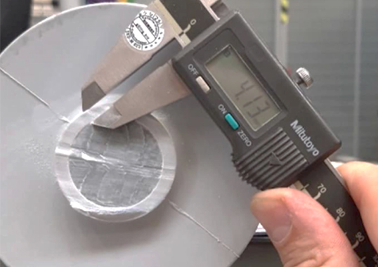
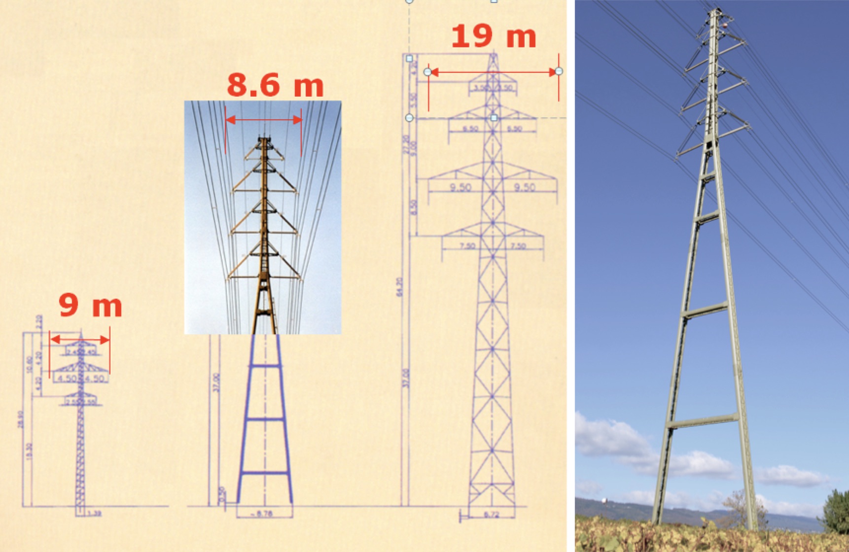
The first 400 kV compact line was installed in Switzerland in 1998. The line became necessary since the existing 125 kV line (see Fig. 12a) was not sufficient to carry increasing power demand in the region of Lake Geneva and had to be replaced with a 400 kV line. Conventional lattice towers normally used for this type of line would require considerable right-of-way, which was not available in a certain location close to buildings. The solution was to design slender 2D towers and apply insulated cross-arms with composite insulators for the 400 kV circuits. These could also support two single-phase 132 kV circuits for feeder lines of the Swiss railway (see Fig. 12b). It is worth noting that FRP core rods available at the time were restricted to 76 mm diameter, which could not take the compression loads. So, hollow core composite insulators had to be used.
Hybrid AC/DC Line
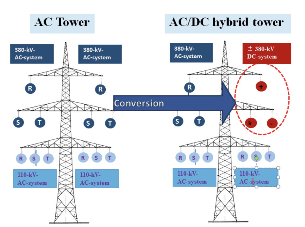
Conversion from AC to DC offers advantages for long distance transmission. In particular, conductors can be utilized up to their thermal limit in DC whereas in AC surge impedance loading (SIL) often becomes the limiting factor. In a pioneer project in Germany, one of the two circuits of a 380 kV AC line has been converted to a ±400 kV DC bi-pole with the third conductor used for the metallic earth return (see Fig. 13). A major prerequisite for this project was to use the same conductors and same towers. This would only be possible by replacing existing porcelain strings with composite insulators since these have significantly better contamination performance. As such, their length can be accommodated within existing tower top geometry.
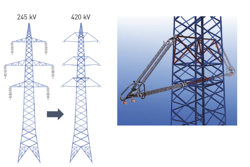
Conversion of 245 kV to 420 kV AC
An interesting project in Austria saw two-fold line uprating. On one side, the original ACSR conductors were replaced by newly designed expanded conductors, i.e. conductors with the same amount of aluminum but with larger diameter to increase current carrying capacity. On the other side, the metallic cross-arms on the lattice steel towers were replaced by insulating cross-arms (see Fig. 14), which enabled increasing line voltage from 245 kV to 420 kV.

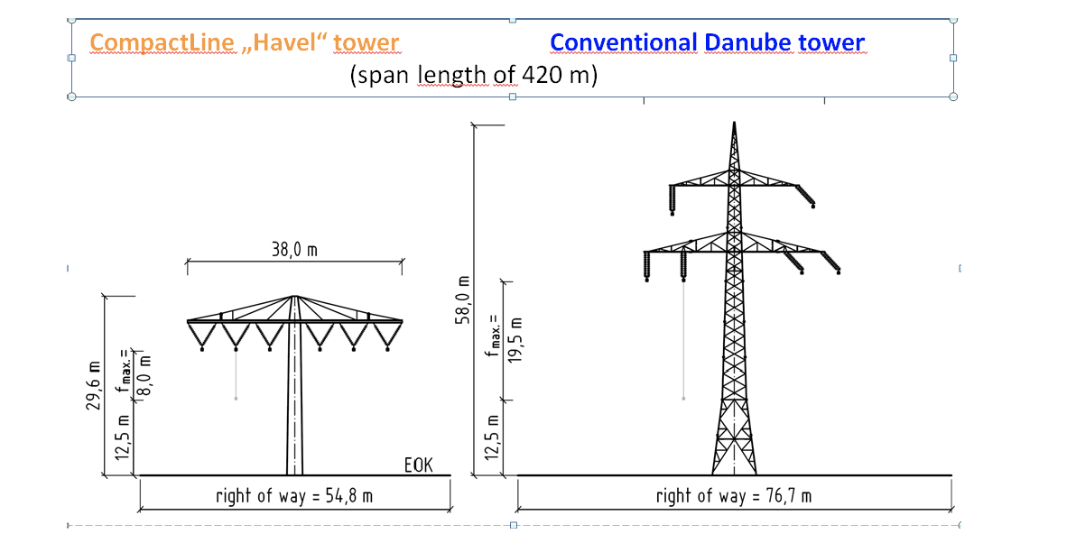
CompactLine
This new concept, developed in Germany, utilized existing 220 kV corridors but with a new design of 380 kV low visibility profile pylon. In order to achieve this, conductor sag had to be limited and this was made possible by suspending the quad bundle conductors to a tightly strung high strength steel rope, as used in cable cars. In order to keep the support top geometry narrow, V-string insulator assemblies had to be used and this is only feasible with high strength composite insulators (see Fig. 15).
![]()
Conclusions
Composite insulators are probably the most important technical innovation in overhead lines over the past decades. Apart from their increasing application in standard line situations to replace porcelain and glass, they have contributed as well to designing compact lines with more aesthetic support structures. Both have promoted greater community acceptance of new line projects.
In addition, due mainly to their excellent mechanical properties, these insulators have also helped line uprating projects, such as conversion of AC to DC as well as stepping up system voltages.
References
[1] Papailiou, K.O., Schmuck, F. (2013): Composite Insulators – Materials, Design, Applications, Springer-Verlag Berlin Heidelberg.
[2] Voyatzakis, Y. (1988): 150 kV transmission lines on tapered steel poles supporting insulator cross-arms in Greece, International conference on overhead transmission line design and construction, London.
[3] Havard, D.G., Nashid, M.S., Meale, J.R., Foty, S.M. (1991): Transmission line compaction in Ontario Hydro, CIGRE Symposium Leningrad, Paper 200-05 Session 33-91.
[4] Baker, A.C., Bernstorf, R.A., Del Bello, E., Farzaneh, M., Hill, R.J., King, B., Philips, A.J., Powell, D.G., Shaffner, D., Steward, G.A., Grisham, T. (2008): IEEE guide for braced insulator assemblies for overhead transmission lines 60 kV and greater, IEEE Trans Power Delivery 23(2),785-791.
[5] CIGRE (2002): Guide for the evaluation of composite line post insulators subjected to combined mechanical loads, Electra 203, CIGRE, Paris.
[6] Baker, A.C., Murray, P.E., Mozer, J.D. (1982): Computer aided analysis of wind loads on horizontal Vee type transmission line systems, IEEE Trans PAS, PAS-101(8):2415–2419.
[7] CIGRE Technical Brochure 294, WG B2.06 (2006): How OH Lines are re-designed for uprating/upgrading, CIGRE, Paris.
[8] CIGRE Technical Brochure 244, WG B2.12 (2004): Conductors for the uprating of overhead lines, CIGRE, Paris
[9] Ammann, M., Papailiou, K.O., Dallèves, P., Leva, M., Villa, S. (1998): A new 400 kV line with compact towers and composite insulated cross-arms, paper 22/33/36-06, CIGRE, Paris.
[10] Sander, B., Lundquist, J., Gutman, I., Neumann, C., Rusek, B., Weck, K.-H. (2014): Conversion of AC multi-circuit lines to AC-DC hybrid lines with respect to the environmental impact, Session paper B2-105, CIGRE, Paris.
[11] Schichler, U., Hadinger, N., Troppauer, W., Babuder, M., Vizinin, S., Reich, K., Leonhardsberger, M., Dchmuck, F., Hussmann, E.(2016): Innovation-Section: Test-run for uprating a 220 kV OHL to 380 kV using insulated cross-arms and coated conductors, Session paper B2-301, CIGRE, Paris.
[12] Behrend, S. (2016: CompactLine – a new Overhead Transmission Line Concept, Session paper B2-307, CIGRE, Paris.