Electric power equipment used on transmission lines and at substations can be exposed to harsh natural conditions such as pollution, lightning, strong winds, snow and icing. To safely transport and supply electricity, it is therefore necessary to design appropriate insulation as well as suitable countermeasures for these types of environmental stresses. In the case of Japan, which is surrounded by the sea, the dominant factors in design of external insulation tend to be maritime salt pollution and powerful typhoons. Based on extensive research and testing since the start of 500 kV transmission, standard insulation designs have been established to prevent salt damage, with suitable insulator length determined by degree of local site pollution severity (SPS).
This edited contribution to INMR by Hiroya Homma, an expert at the Central Research Institute of Electric Power Industry (CRIEPI), outlines development of insulation designs as well as countermeasures for transmission insulators in Japan. In addition, it discusses performance of insulators under natural conditions and the results of artificial pollution tests, which forms the basis of the standard insulation designs currently used. Finally, status of current research at CRIEPI is reviewed in relation to polymeric insulators which are now increasingly being applied in Japan.


Monitoring performance of transmission insulators under pollution conditions is extremely important in design of power equipment and extensive research on this has been carried out, both in Japan and internationally. As a result, widespread insulator problems caused by salt pollution in Japan have decreased since the 1970s while reliability of transmission lines has improved significantly. Moreover, standard insulation designs have been established and it has become possible for Japanese power utilities to efficiently define their optimal insulation requirements.
Major Outages from Sea Salt Pollution
Typhoons and strong seasonal winds are among the main causes of salt damage to insulators in Japan. Such damage tends to be widespread and lasts a long time. For example, serious outages due to salt contamination were caused by the 2nd Muroto Typhoon in 1961 and later Typhoon No. 19 in 1991. More recently, a huge outage followed Typhoon No. 24 in 2018.
The characteristic common to these major salt incidents was that all were caused by large-scale typhoons that crisscrossed the Japanese archipelago. The 2nd Muroto Typhoon recorded maximum wind speeds of 60 m/s and even caused damage inland as far as 75 km from the coast. Some areas suffered loss of power for as long as 15 days after the typhoon.
Measures to prevent salt damage were strengthened and the security level of transmission lines improved each time a serious outage occurred. As a result, the number of such incidents has progressively become extremely low. However, while the number of such accidents has been reduced in areas where prevention measures were implemented, salt damage to insulation performance has still occurred where sufficient measures have not yet been undertaken, such as relatively far from the coast.

Basic Concept of Insulation Design in Japan
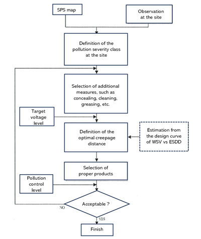
The goal of insulation design against salt pollution is to determine the optimal number of suspension disk insulators in the string as well as required creepage distance for long-rod and hollow bushing insulators corresponding to the level of environmental contamination. Fig. 1 is a schematic detailing the standard procedure for insulation design in Japan. Currently, each power utility in Japan defines its salt-resistant designs and operations according to this same procedure. The basic insulation design concept comprises three common elements:
1) Voltage Condition
Target withstand voltage of the transmission lines (maximum voltage and overvoltage);
2) Contamination Condition
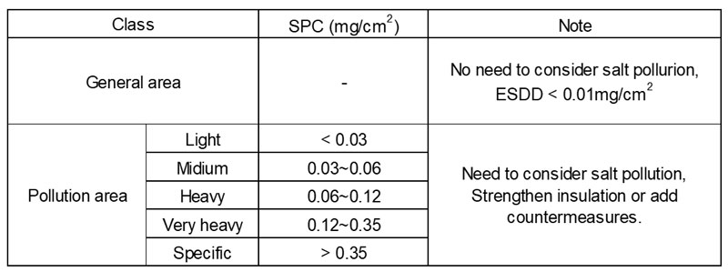
SPS classes (maximum amount of salt deposition adhering to insulation in the area);
3) Insulation Performance of Applicable Insulators
Withstand voltage curves versus equivalent salt deposit density (in natural and artificial pollution).
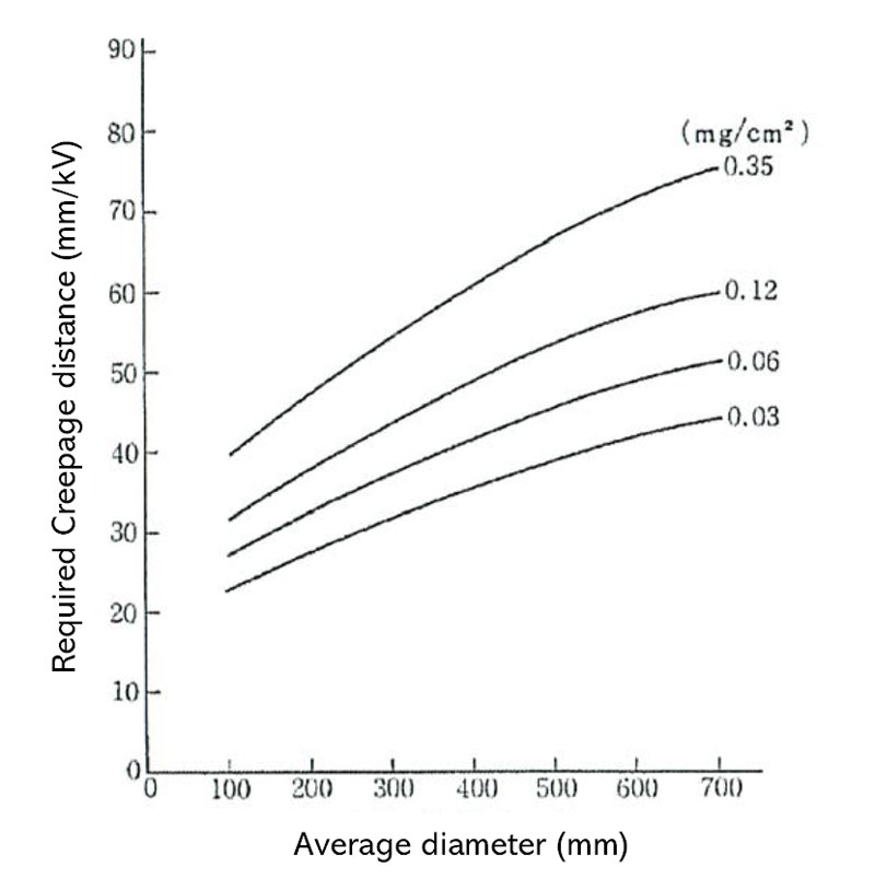
In this regard, the increased voltage at the time of a single line to ground fault is used as the target withstand voltage of lines. Moreover, SPS levels are categorized by the supposed maximum salt deposit density in the area (see Table 1). In addition, countermeasures such as protecting, cleaning and greasing are all considered, as necessary. Withstand voltage properties of contaminated insulators (i.e. as per Figs. 2 and 3) will be explained later.

Performance of Insulators in Polluted Environments
Regarding withstand voltage performance of insulators in polluted service environments, it is important to understand the state of pollution severity affecting insulators as well as their electrical insulation performance when flashover occurred. Below is an overview of investigations and tests related to pollution properties and insulation performance of various insulators under natural conditions.
Characteristics of Salt Deposition on Insulators
To elucidate the characteristics of contaminated insulators, a wide- ranging survey was conducted of pollution conditions in environments across Japan, including Akita, Noto and Takeyama. Geographical conditions were also examined such as distance from pollution source, topography, wind velocity and direction and rainfall from typhoons. The relationship of all these factors with weather conditions was then evaluated.
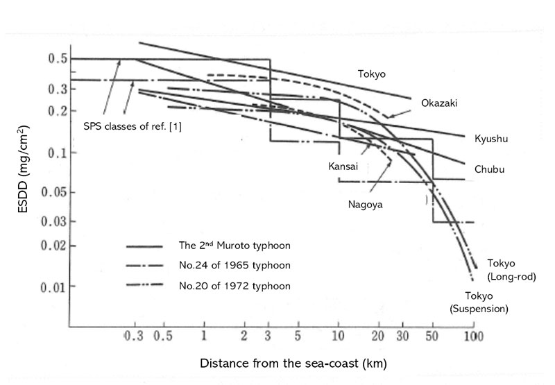
Locations where large amounts of salt tend to accumulate on insulator surfaces include areas that are close to the coast or on flat land or near rivers. Then, based on long-term field observations in various parts of the country, distance characteristics from the coast were approximated (see Fig. 4).
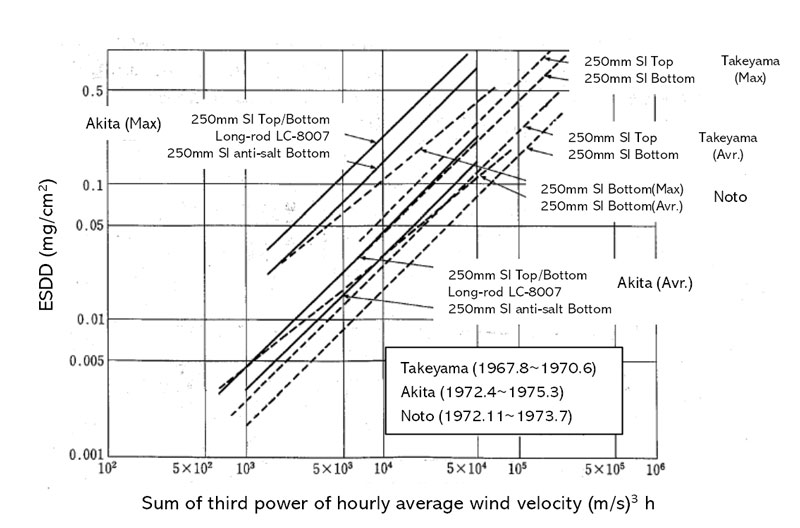
In cases when rapid contamination is caused by strong winds during typhoons and where the amounts of contamination increase rapidly (i.e. on the order of only several hours in the case of no precipitation), it was found that the amount of salt deposit increases approximately to the third power of average hourly wind speed, v, in m/s (see Fig. 5).
In regard to pollution severity, the maximum amount of salt deposit expected at each site was predicted based on observed results. Risk of damage from the salt was then evaluated. Japanese electric power utilities set pollution categories in their service areas based on estimated amount of salt deposition (i.e. ESDD) and create pollution severity maps that also take into account various geographic conditions. These maps are then employed to design insulation used at relevant locations.
By installing automatic contamination detection and measurement instruments at substations and utilizing various meteorological data (e.g. wind direction and speed, precipitation), utilities can decide the appropriate timing of countermeasures, such as determining best time for cleaning. Moreover, since performance and pollution properties of applied insulators change depending on their type and shape (e.g. average diameter), correction factors have been determined to account for these differences.
Artificial Pollution Tests Carried Out in Japan
To clarify the relationship between amount of salt contamination and dielectric breakdown strength of insulators, artificial pollution tests were conducted. These tests investigated the withstand voltage properties of various insulators.
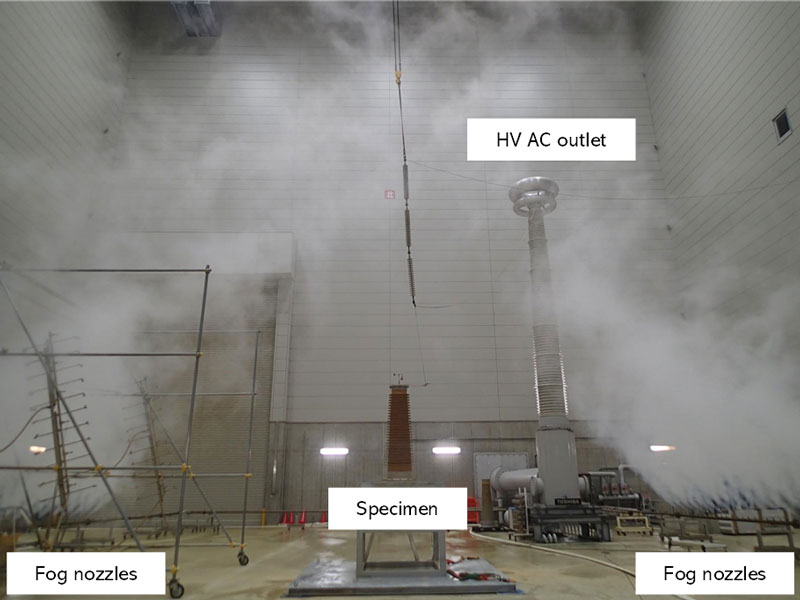
Artificial pollution tests carried out in Japan are based mainly on the clean fog method prescribed in JEC-0203 standard of the Japanese Electrotechnical Committee. This has also been adopted as the standard test method in many other countries as well as in IEC 60507. In addition, the equivalent fog method, unique to Japan, is standardized in JEC-0203. The clean fog method sees a contaminated liquid of specified concentration applied to the insulator surface and dried. Subsequently, flashover is caused by generating steam fog in the test chamber while voltage is applied. This method takes into account the actual wetting process in the field and simulates conditions close to those in the natural environment. However, such testing requires a fog chamber and fog generators, making it a relatively large-scale facility and a more complicated test procedure. This stands in contrast to the equivalent fog test method, which involves coating the insulator surface with a specified liquid contaminant. By applying a voltage while the specimen is contaminated and wet and increasing the voltage until flashover occurs, polluted insulation characteristics can be obtained efficiently, easily and rapidly.
Relationship Between Flashover Voltage & ESDD
For either of the above test methods, as density of salt deposition on the surface increases, insulator withstand voltage decreases. Past results, for example, have shown that the flashover voltage of a contaminated insulator is approximately proportional to the -0.2 power of equivalent salt deposit density.
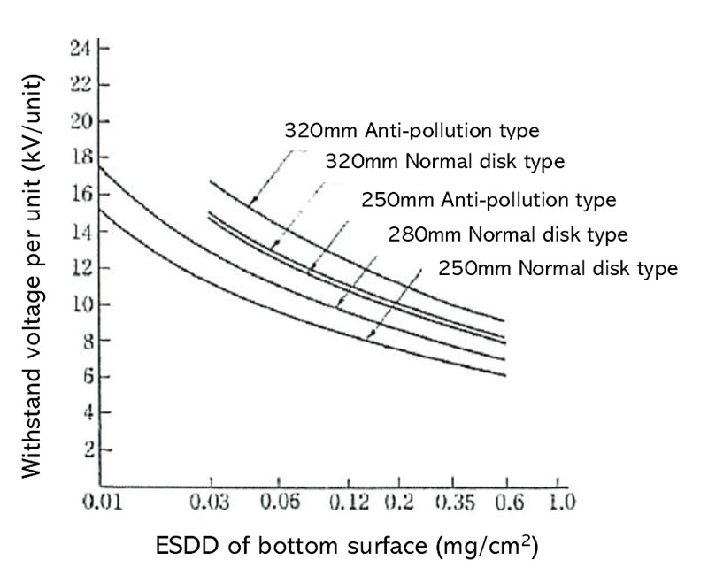
Insulation properties of suspension disk insulators with individual metal connections (metal electrodes) in terms of withstand voltage per creepage distance of insulator (unit: kV/piece or kV/m) have also been evaluated. By contrast, for cylindrical insulators such as long-rod insulators and hollow insulators with metal electrodes at both ends, required leakage distance per kV of AC voltage is determined (i.e. unit: m/kV). For these types of insulators, insulation properties are affected by shank diameter. As average diameter increases, required leakage distance also increases.
Outdoor exposure tests were conducted between 1968 and 1980 in three different areas: Akita, Noto and Takeyama Test Stations. Results of flashover voltage acquired from these natural sea-salt environments were then plotted against the performance curves established from artificial fog testing. Fig. 6 shows flashover voltages for different levels of ESDD of the bottom surface of a standard 146 x 250 mm suspension disk insulator in an actual service environment and compares these with results obtained from artificial pollution testing. The equivalent fog test method could therefore prove useful to determine the pollution characteristics of insulators as an alternative to the clean fog method.
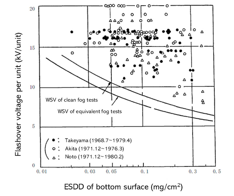
suspension disk insulators at Akita, Noto & Takeyama compared to
withstand voltage characteristics from artificial pollution tests.
Application of Polymeric Insulators in Japan
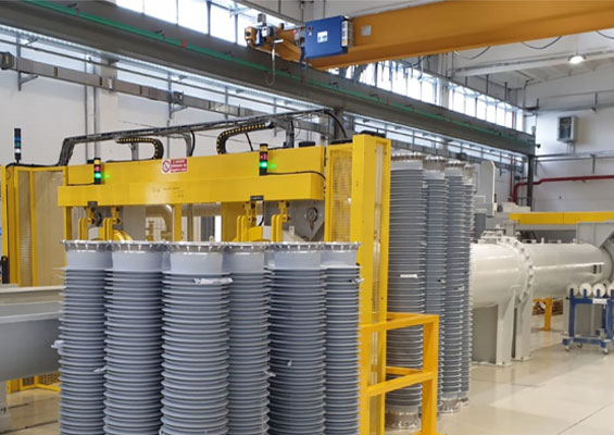
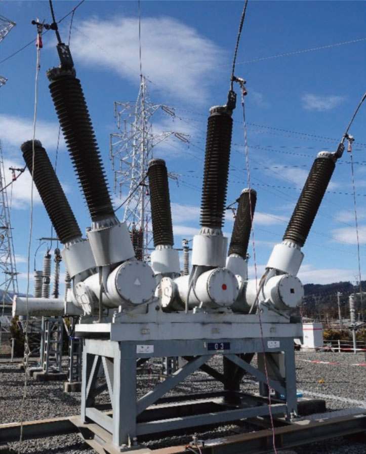
Polymeric insulators and bushings are lighter and offer greater flexibility in design than conventional porcelain insulators. As a result, their application in Japan has expanded from distribution to high voltage transmission lines and substations. In particular, after the Great East Japan Earthquake if 2011, polymeric insulated substation equipment has progressively replaced porcelain as part of earthquake resistance measures (see Fig. 7). Subsequently, the latest design standards and test methods were compiled in January 2017.
Recent CRIEPI Research on Outdoor Insulation
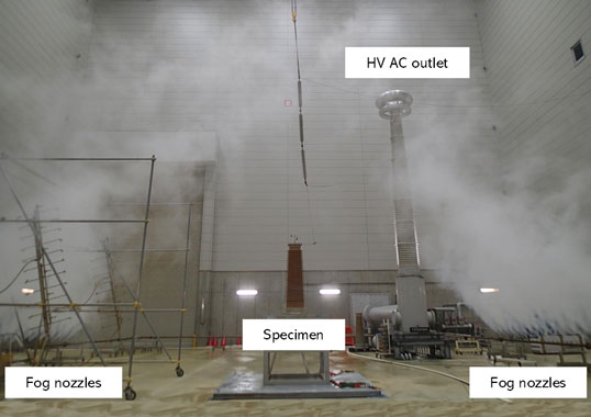
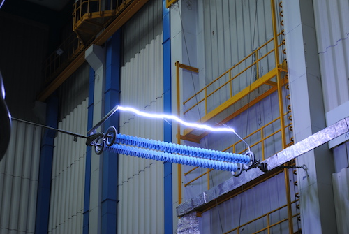
CRIEPI operates test facilities such as a HV test hall and coastal exposure test station at its Yokosuka laboratory in Kanagawa Prefecture. This test hall, measuring 31m x 35m x 30m (height), was re-constructed in 2008 and equipped with a steam fog generator, an AC 900 kV test transformer and a 2600 kV impulse generator. To evaluate risk of surface degradation and clarify the long-term reliability of polymeric insulators, various kinds of artificial tests were conducted in this facility, including the clean fog method (see Fig. 8), the equivalent fog method and the salt fog method, among others. Depth profile of any surface degradation in silicone rubber materials was evaluated by microscope observations of the cross-section of shed materials. There have also been efforts to develop non-destructive diagnostic methods using advanced optical techniques such as laser induced breakdown spectroscopy.
Salt & Snow Damage Caused by Blizzards
Excluding damage from lightning, the dominant factor in the design of external insulation of power transmission equipment in Japan has been maritime pollution. Still, some transmission lines and substations operate in areas where there is risk of heavy snowfall. In December 2005, for example, a ground fault from salt laden snow occurred on 66 kV and 154 kV lines in the Joetsu region of Niigata Prefecture. Snowfall was accompanied by strong winds that caused wet snow packed with salt to fill the space between insulator sheds. In fact, the large amount of salt carried some 30 to 40 km inland, in combination with snow clouds, caused numerous long-term power outages. To prevent recurrence of such salt and snow damage there was therefore a need to elucidate snow accretion characteristics of insulators as well as their insulation properties during accretion. This was accomplished both through on-site observations and artificial snow tests.
Influence of Volcanic Ash Adhesion
The Japanese archipelago is one of the world’s most active volcanic regions and there are concerns that large-scale eruptions could disrupt power supply. In the case of overhead transmission lines, performance of insulators is expected to deteriorate should there be widespread volcanic ash fall during an eruption. Given this, it has been seen as important to determine the extent of such impact and develop strategies to minimize outages as well as recover as quickly as possible.
For example, the eruption of Mount Aso in October 2016 caused deterioration of insulation on 66 kV transmission lines and also at nearby substations, affecting power supply to some areas. Up to now, various types of volcanic ash have been collected for evaluation and flashover tests were conducted to simulate volcanic ash adhesion onto insulators. The challenge in this regard has been to understand all the characteristics of volcanic ash adhesion and effect on insulation performance. Properties of deposition on some kinds of insulators were investigated and flashover tests initiated under wet conditions by means of artificial pollution tests using actual volcanic ash.

References:
[1] Denki-Kyodo-Kenkyu, Vol. 20, No. 2, 1964. (In Japanese)
[2] Denki-Kyodo-Kenkyu, Vol. 35, No. 3, 1979. (In Japanese)
[3] Denki-Kyodo-Kenkyu, Vol. 20, No. 1, 1964. (In Japanese)
[4] Denki-Kyodo-Kenkyu, Vol. 20, No. 3, 1964. (In Japanese)
[5] Denki-Kyodo-Kenkyu, Vol. 51, No. 3, 1996. (In Japanese)
[6] JEC-0203:”High-voltage tests in general”, 2022. (In Japanese)
[7] IEC 60507: “Artificial pollution tests on high-voltage ceramic and glass insulators to be used on a.c. systems.”, 2013.
[8] N. Arai; “AC Withstand Voltage Characteristics of Contaminated Insulators”, CRIEPI Report, No. 124, 1986. (In Japanese)
[9] M. Sakata; “Application of Polymer Insulators for Varying Natural Environments in Japan”, INMR World Congress, 2022.
[10] “Standardization of design and testing method of hollow polymer insulators”, Denki-Kyodo-Kenkyu, Vol. 72, No. 4, 2017. (In Japanese)
[11] H. Homma et al; “Determination of long-term performance of polymeric insulators for distribution lines by salt fog method”, CEIDP, pp.401-404, 2006.
[12] H. Homma et al; “Evaluation on Depth Profile of Surface Degradation of Polymeric Insulators by Microscopic Observation of the Cross Section”, ISEIM, E-2, pp.198-201, 2020.
[13] T. Homma et al; “Depth profiling of surface degradation of silicone rubber composite insulators by remote laser-induced breakdown spectroscopy”, Spectrochimica Acta Part B: Atomic Spectroscopy, 180, 2021. (https://doi.org/10.1016/j.sab.2021.106206)
[14] K. Yaji et al; “Evaluation on Flashover Voltage Property of Snow Accreted Insulators for Overhead Transmission Lines, Part I —Field Observations and Laboratory Tests to Evaluate Snow Accretion Properties”, IEEE TDEI, Vol. 21, No. 6, pp.2549-2558, 2014.
[15] K. Yaji et al; “Evaluation on Flashover Voltage Property of Snow Accreted Insulators for Overhead Transmission Lines, Part I —Flashover Characteristics Under Salt Contaminated Snowstorm”, IEEE TDEI, Vol. 21, No. 6, pp.2559-2567, 2014.
[16] H. Homma et al; “Evaluation on Flashover Voltage Property of Snow Accreted Insulators for Overhead Transmission Lines, Part III – 154 kV Full-scale Flashover Voltage Test of Snow Accreted Insulators -”, IEEE TDEI, Vol. 21, No. 6, pp.2568-2575, 2014.
[17] I. Gutman; “Effect of Volcanic Ash on Outdoor Insulators”, INMR, June 1, 2023. (https://www.inmr.com/effect-of-volcanic-ash-outdoor-insulators/)
[18] H. Homma et al; “Influence of volcanic ash deposits on insulating performance of transmission insulators – Properties of volcanic ash deposition and flashover in wet condition-”, CRIEPI Report, H18016, 2019. (In Japanese)