American Transmission Company (ATC) own and operates transmission lines in the States of Wisconsin, Michigan, Minnesota and Illinois. The system originally belonged to local utilities that had different standards and this resulted in a variety of different line surge arrester installations at 69 kV and 138 kV. To document which of these adhered to industry best practice and which might need improvement, the Electric Power Research Institute (EPRI) was contracted to perform a visual site review and assessment.
First, a records search established where arresters were installed and a representative sample of 25 installations on 12 lines was selected for study. These ranged from ‘one-offs’ and special designs to those that met current ATC standards. The sites covered during this review revealed installations that followed good practice but also a number of less-than-ideal installations with reduced functionality or which could experience problems if the arrester fails.
This edited 2019 contribution to INMR by Consulting Engineer, Bryan Beske, reviewed findings from the inspection along with recommendations for improvement whenever concerns were identified.
Effective TLSA Installations
Installations that adhered to good industry practice and where no improvements were deemed necessary were identified on 5 lines having 6 different configurations. These included arresters mounted across insulators that were horizontally as well as vertically mounted. The fifth installation was unique and not typical. While some of these installations might be considered unconventional, they were nonetheless rated operationally acceptable both for the in-service condition and should the arrester fail. Included here were two installations that are more than 40 years old and that, while still in-service, might no longer function as intended (see Figs. 10 & 11).
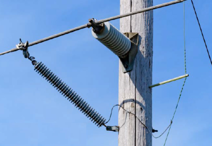
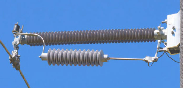
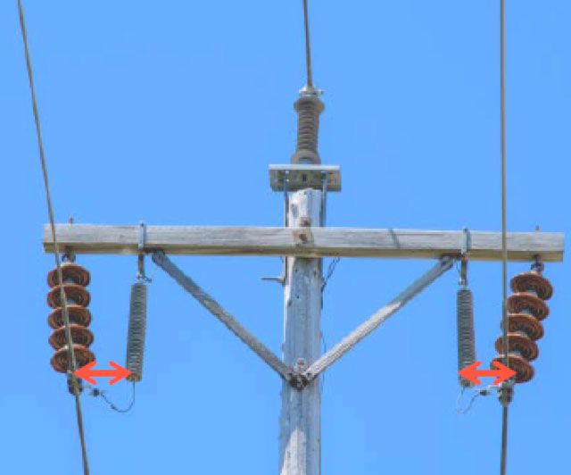
The first installation type was on 69 kV lines where all three phases are supported by horizontally mounted polymeric post insulators (see Figs. 2 & 3). Examples include one line that does not have a static wire and with underhung mounted arresters on all three phases (Fig. 2) and another line having a static wire where the arrester is installed only on the bottom phase (see Fig. 3).
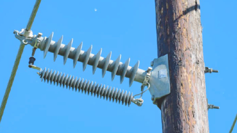
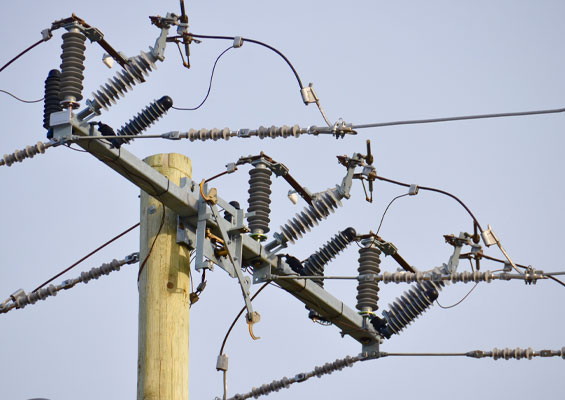
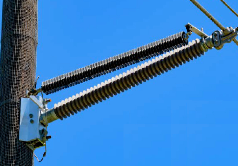
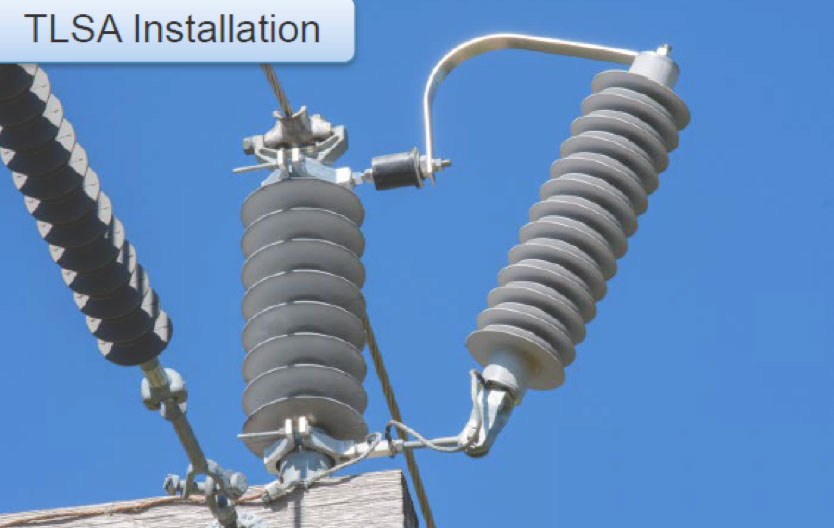
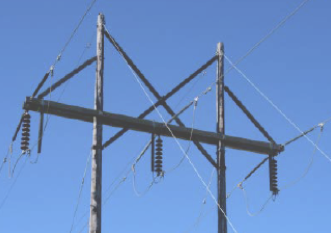
The second installation type evaluated was on a 69 kV line with woodpecker wrap (see Figs. 4 & 5). A vertical polymeric post insulator supports the top phase and two horizontally mounted back-to-back polymeric post insulators support the lower phases. The top phase has a vertically mounted arrester while the bottom two phases have side mounted arresters. Higher insulation value insulators were used for the bottom phases to maintain adequate climbing space between phases.

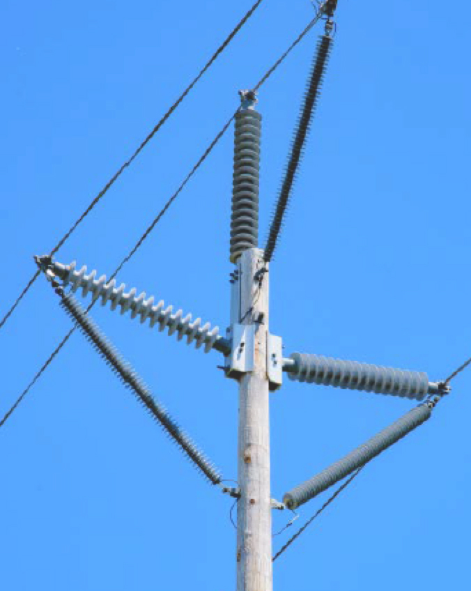
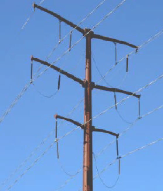
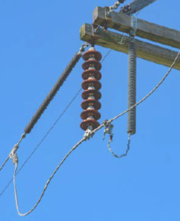
The third installation type was on a 138 kV line with no shield wire in this section (see Fig. 6). The top phase wire in this example is supported by a vertically mounted polymeric post insulator and horizontally mounted back-to-back polymeric post insulators support the bottom two phases. The top phase has a vertically mounted arrester while the bottom two phases have side mounted arresters.
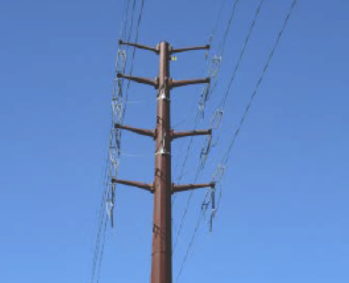
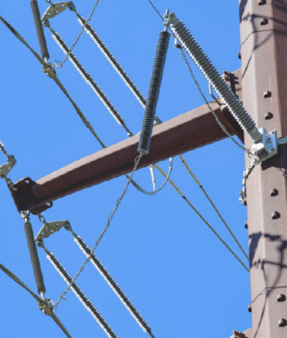
The fifth installation type involved a 138 kV line with two shield wires (see Figs. 7 & 8). In this case, arresters are installed on all three phases of both circuits over the entire length. The installation on this line is unique in that it is a double dead-end structure utilizing horizontal line post insulators to support arresters for the top and middle phases. Bottom phase arresters are hung from the phase conductor jumper.
The sixth installation type involved a 69 kV line with a single shield wire (see Fig. 9). For this line, a standoff ground is used in the wire zone to increase effective BIL of the structure and arresters are installed only on the bottom phase. Due to the standoff ground, an 88 MCOV arrester was used for the additional length needed to bridge the distance between phase wire and a lower point on the structure ground.
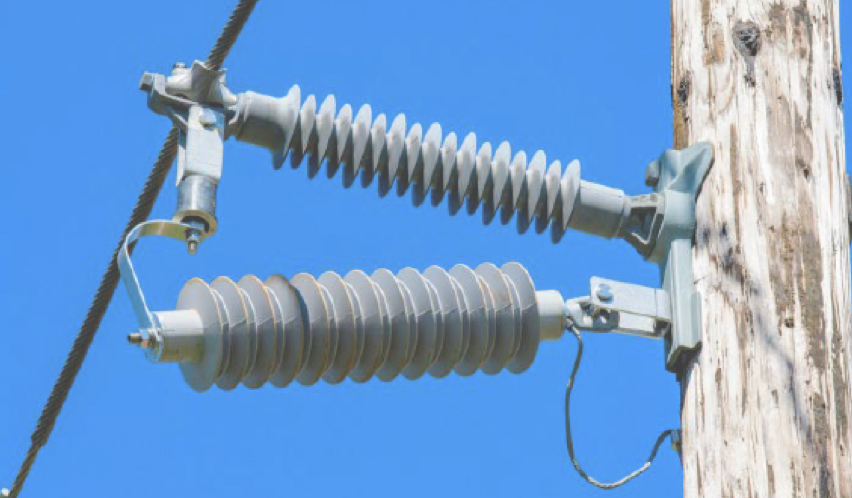
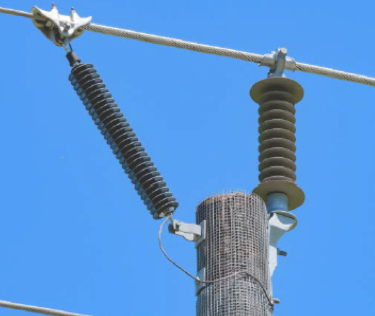
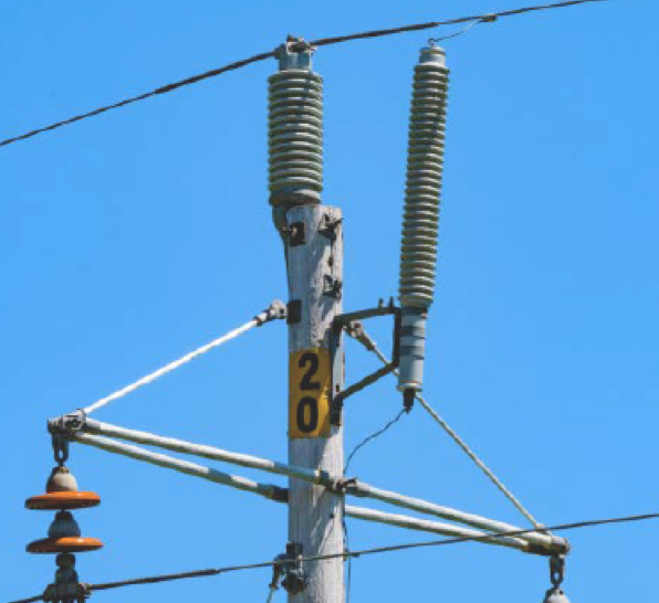
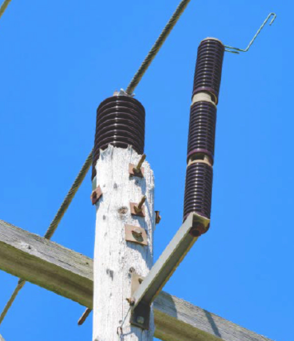
The seventh and eighth installation cases reviewed utilized older silicon carbide arrester technology and are installed on 69 kV lines without static wires (see Figs. 10 & 11). Arresters in these installations are mounted to protect the top phase, supported by a vertical porcelain post insulator on the pole top.

Installations With Recommended Improvements
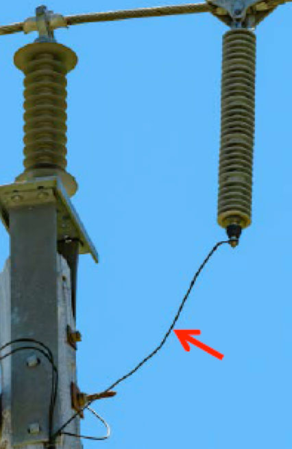
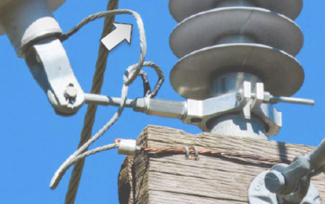
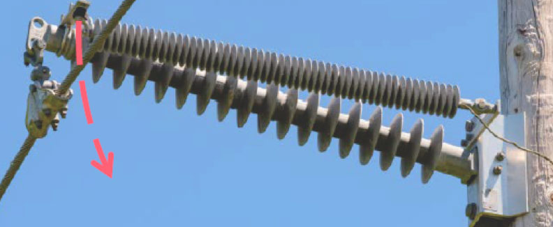
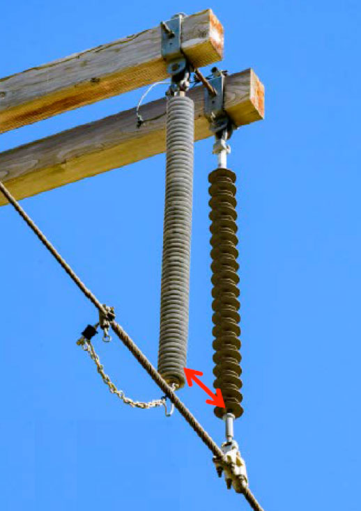
There were a number of cases of installations where improvements were recommended. While electrically functional as installed, these could nonetheless experience compromised arrester and other equipment function or other issues if the arrester were to fail. For those installations where functionality of the arrester could be compromised, the typical problem involved lead length and/or positioning. For example, on installations where the only concern was long lead length, there was risk of whiplash to the arresters (see Fig. 12) and possible lead fatigue under windy conditions (see Figs. 13 & 14).
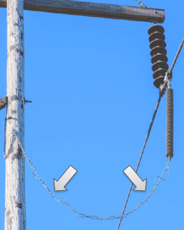
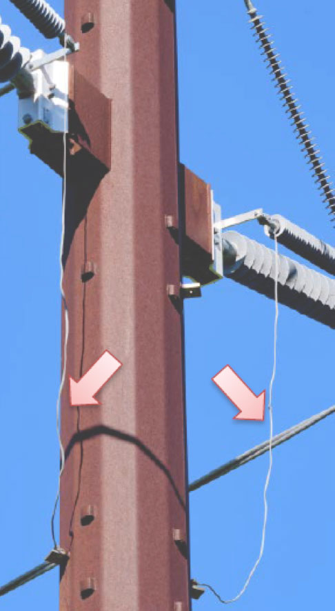
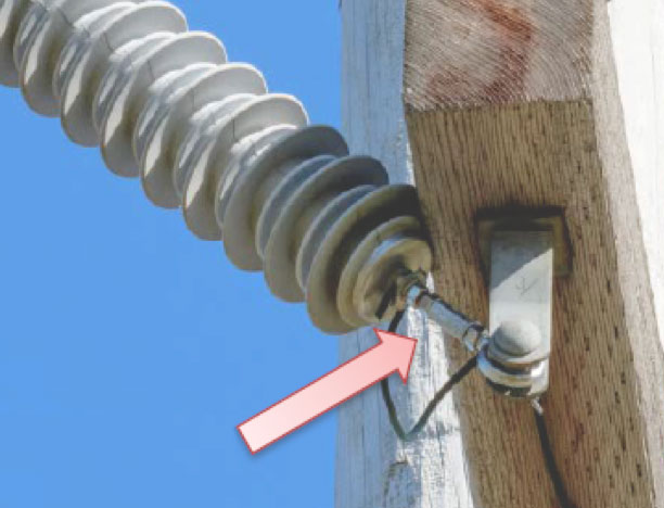
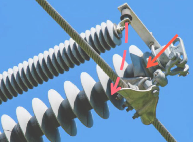
For those installations where lead length or arrester positioning could compromise functionality of the arrester or other equipment, the typical issue was placement and/or length of the lead in relation to adjacent insulation. While this did occur at the live end in some installations (see Fig. 15), the more typical occurrence was on the ground lead (see Figs. 16 & 17). Another instance with compromised insulation was where the arrester presses against the cross-arm (see Fig. 18). This compromises arrester insulation BIL and also risks mechanically stressing the arrester housing, which could lead to premature failure.
Other cases where improvements were recommended involved installations with design flaws such as:
• excessive lead length that could cause sustained outages if the arrester fails (see Figs. 19 & 20),
• the arrester not being able to fall clear if the disconnect operates (see Figs. 21 to 23), or
• insufficient clearance from arrester to phase wire if the arrester fails (see Figs. 24 to 27).
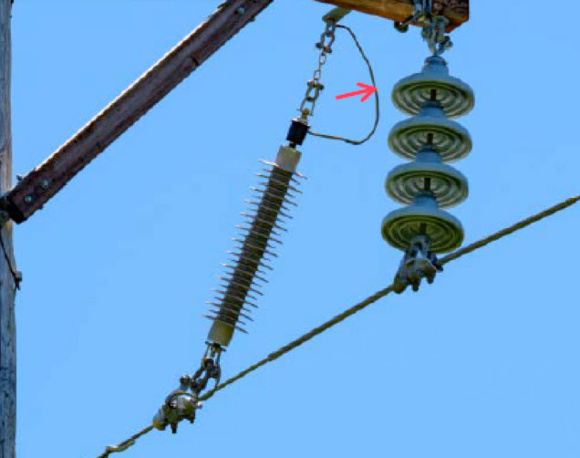
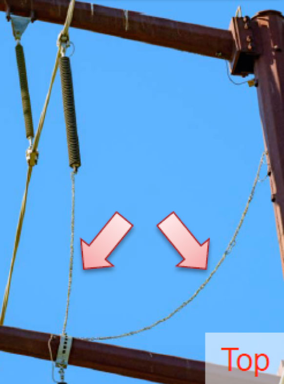
While these installations may function properly, if the arrester were to fail the result would be multiple momentary or a sustained outage until a field crew arrived to clear the issue. In the case of the example with excessive lead length, this is the same line as shown in Fig. 7. Figs. 20 and 21 shows a typical structure along this line. For this installation type, the design saw the top phase arrester hang from phase conductor and jumper back to the pole with the ground lead. To accommodate this, long lead length needed to be specified. For the middle phase, an arrester was then hung from the middle phase cross-arm using a pole band and jumpered to the phase wire. To accommodate mounting the middle phase arrester to the arm, a pole band was used that has a vertically protruding bolt at the top of the arm. Given that the top phase arrester was offset from the plane of the structure, its lead appeared to be clear of any interference from the middle phase arm.

Over time, however, it became clear that the impact of the lead swinging in the wind had not been accounted for. Lead length was sufficient to get caught on the vertically protruding bolt of the pole band used to mount the middle phase arrester. In the event the arrester were to fail and should the lead remain snagged on the protruding bolt, the lead would fall directly across the middle phase arrester, likely resulting in a sustained outage until removal by a field crew.
Another design flaw identified involved operation of the disconnect, whereby the arrester would likely not fall clear of the phase conductor and cause the line to remain out-of-service until it could be removed by a field crew. Also, Fig. 23 shows a design issue since the structure in this case has an angle on it with sufficient conductor tension to cause the suspension clamp to encroach on and compress several sheds of the insulator.
Yet another design flaw identified during visual inspection related to not enough clearance between any arrester that failed and the phase conductor. In the event of failure, insufficient clearance would likely result in multiple momentary outages as the arrester and/or conductor sway in the wind. The affected line would then have to be kept out-of-service until a field crew removed the failed arrester.
Conclusions
While many of the installations shown above were designed, built and operated as expected, other installations presented issues that needed to be addressed. Somewhere during the design or installation phases of the projects for these arresters, critical issues were missed or poor practices used.
It is important to know how a line arrester functions and what happens should it fail in order to identify any issues that might arise from a ‘make it fit’ philosophy employed during construction. The challenge is to ensure that these issues are addressed before they end up in the field and the line is energized. Documenting these recommendations from EPRI has created a valuable teaching tool for line arresters that will be used by ATC designers, engineers and construction personnel.
_________________
RELATED ARTICLES:
Experience with Application of TLAs on 400 kV Line
Achieving Long Service Life from Transmission Line Arresters