Lightning has been reported as the main cause of unscheduled outages on overhead sub-transmission and transmission lines (e.g. U.S.: 57%; Brazil: 50-70%; Japan: 70-80%; Denmark: 57%; Colombia: 47-69%). Reducing outages due to lightning has a major impact on overall reliability of both distribution and transmission lines. The main aim of installing transmission line arresters (TLAs) is to reduce tripping/outages on shielded or unshielded lines. Tripping generally arises from insulator flashovers – commonly known as back-flashovers, since the tower is no longer at earth potential but due to the lightning surge at higher voltage than the conductor:
• Unshielded Lines: Lightning strikes to the structures or the phase conductors will, in almost all cases, produce flashovers along the insulator strings.
• Shielded Lines: Strikes to the structure or earthwire have the possibility of backflashover occurring across the insulator strings depending, amongst other parameters, on the level of strike current and the transient grounding system behaviour.
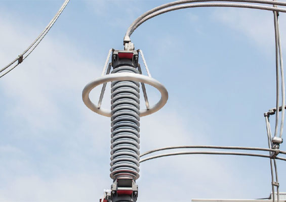
Transmission line lightning performance also depends on correct choice of arrester type and positioning on the structure and along the line. It is possible to significantly reduce lightning caused outages by having TLAs on every phase on every structure but this will rarely be economical and the overall failure rate of the TLAs may then reduce transmission line performance. It is therefore necessary for a power supply utility to specify an acceptable performance level and work from there.
This edited past contribution to INMR by Dr. Brian Wareing, Overhead Lines & Lightning Protection Consultant based in the U.K., provided an example of choice and positioning of TLAs on a double circuit 400 kV line.


An evaluation was required to increase the reliability of the 400 kV Beauly-Denny line that crosses the North Scottish Highlands from near Inverness to just west of Edinburgh. The major problems affecting reliability are severe weather conditions (snow, ice and winds up to 65 m/s) and lightning triggered outages. Investigations into line design were introduced to reduce the impact of the effect of the severe weather expected, especially in the Corrieyairack area where the line rises to around 800 m. The risk of the line being struck by lightning with consequential back-flashover and tripping out of circuits was then investigated. The back-flashover situation commonly caused by lightning strikes is usually mitigated by a low value of tower earthing. However, in many parts of the line the ground is granite with soil resistivities >20,000Ωm. Obtaining low value tower earths would therefore be expensive and, in places, virtually impossible. The alternative to reducing back-flashovers is the transmission line arrester (TLA) and a full analysis of how this could used to produce a reliable line within financial constraints. This analysis was then used to determine the necessity or otherwise of providing possible costly earthing solutions. So the TLA method was compared with the cost of introducing earthing mitigation measures to produce the most reliable and economic solution. The initial target was to prevent 95% of strikes causing a back-flashover.

Back-flashover Scenario
Back-flashovers
Back-flashover is the situation when the difference between the voltage on the cross-arm (created by strike current to the earthwire travelling to earth down the tower) and that on the phase conductor (both with respect to the same earth) exceeds the BIL of the phase insulator arc gap. This can put a sharp fronted overvoltage waveform onto the phase conductors – a particular problem on substation approach. A backflashover is generally agreed to be the situation where the tower is at high voltage compared with the phase wire instead of approximately at earth level, since it would be in the case of flashover from a direct strike to a phase conductor. The back-flashover-generated surge has a very sharp wavefront as the arc causes the phase wire to jump in <1µs from an induced voltage level (from the surge along the earthwire) to virtually the full lightning surge voltage as present on the tower cross-arm (the arc itself will drop a few hundred volts only).
Back-flashover Probability
The probability of a flashover is dependent on the voltage across the insulator i.e. between the tower crossarm voltage and the voltage on the phase conductor (induced voltage plus normal 50 Hz voltage). To calculate this it is necessary to calculate the surge impedance of all the phase and earthwires, which requires knowledge of local ground resistivity, and determine how much surge voltage is induced by the earthwire onto the phase conductors. This requires a calculation of the coupling factor between the earthwire and the phase conductors and requires knowledge of the ground resistivity. This is also dependent on the tower type (distance of conductors above ground) and the tower footing resistance. The crossarm voltage is also dependent on the strike current, earthwire impedance and the surge impedance of the tower and ground. In dealing with the latter it is always necessary to look at the system when subject to a MHz phenomenon and not a 50 Hz scenario. Hence the process is dealing with surge impedance and not resistance.
Once the surge voltage at the cross-arm is known and compared with the phase wire voltage, the probability of flashover depends on the position on the 50 Hz cycle and the ±15% of the mean impulse (50%) breakdown level of the arc gap. The probability of flashover of the insulator will also depend on the waveform of the lightning surge as it appears at the crossarm level. This is currently the subject of work by SSE at Heriot Watt University in Edinburgh. The frequency of the flashover event can then be determined from the local lightning activity. The Heriot Watt PhD project takes a fresh approach at adding to the understanding of the effect of lightning strikes on an overhead transmission line in terms of its electrical behaviour such as charge and voltage propagation around towers and lines. It is reviewing and developing models to simulate this behaviour. This is to enable the answering of questions such as: where should transmission line arresters (TLAs) be placed, on the top, middle, bottom conductor or all and how efficient they are at reducing back-flashovers.

Evaluating Lightning Risk
General
A simplified method of determining the lightning risk and eventually the back-flashover risk per tower uses the average lightning strike density and strike current as well as a simplified calculation for the tower surge impedance. A full investigation would cover the range of lightning strike currents (not the average) and the surge steepness plus corona losses and calculation of the surge impedance for each section of the tower.
It is important to note that lightning strike parameters vary regionally and it is recommended that local data be used if available to increase the accuracy of the overall evaluation of overvoltages and back-flashover risk on transmission lines. In evaluating the strike risk along the Beauly-Denny route, historical data on strikes were obtained within a 1 km radius of each tower. This radius was chosen since this is the approximate distance that a lightning voltage surge on the line will travel before corona losses, etc cause the strike to dissipate.
Evaluating Strike Rate & Current
The strike rate is obtained from a calculation of the collection width for each line section on the Cigré basis where the horizontal attraction, ld, distance for lightning strikes to an OHL conductor is determined from the positions in space of the various phase conductors and earthwires and is obtained from the expression:
ld=C •K0 •I0.74•h0.6
where:
ld = horizontal attraction distance (m)
C = line factor (dependent upon type of line),
for bare wire C = 0.84
I = lightning current (kA)
h = height above ground of the overhead line conductor (m)
K0 = topography factor (for flat open terrain, K0 = 1.0 but can vary from 0.7 for valleys to >2.0 for hill tops)
The above calculation gives the collection area of lightning strikes for each tower on the line as 2 x ld x 2/1000 km² as the tower could, in theory, be reached by surges from 1 km away. Once the collection area is established, it is multiplied by lightning strike density to obtain the lightning risk per annum. The average strike current is then determined from the data. In practice, due to the lower surge impedance of the towers (~200Ω) compared with the conductors (350 to 500Ω) most of the surge current will go down the first tower a surge along the earthwire meets and so this tower will be the most susceptible to back-flashovers. The surge impedance of a tower can be calculated from the size of the individual vertical steelwork sections and the distance they are apart plus an allowance for the closeness of the ground. This is a complex process and a simple, though less accurate, method is given in IEC 60071-2:
Zt = t.((W.ln(4h/W)/(32.π.AW))0.5 + 6.5
where:
t is the transit time (s)
W is the tower base width (m)
H is the tower height (m)
AW is the average tower width (m)
Average self and surge impedances of have been calculated for the earth wire of the Beauly-Denny line for the range of tower types and locations. The earth wire surge impedance varies between 498Ω – 548Ω according to the local ground resistivity values. The tower impedance varies from 170Ω for a D55 M3 tower (high angle of deviation and low height) to 244Ω for a DL E15 (in-line suspension extended height tower). The surge impedance of a conductor, Z, is determined from Z = √ (L/C) where L is the inductance and C the capacitance of the conductor. In a simplified format, the earthwire surge impedance, Zew, is calculated from:
Zew = 60 x ln ((h +S)/r)
where: S = 659 x √(ρ/f)
where:
h – average height of EW above ground (m)
r – Nominal earthwire radius (m)
S – calculated depth of the image of the earthwire in the ground (m)
ρ – ground resistivity (Ωm)
f – frequency (Hz)
The surge impedance of a twin bundled conductor is calculated in a similar fashion but takes into account the lowered inductance of the two phases.
Evaluating Flashover Risk
Incident Surge Impedance
Once the frequency and magnitude of lightning current surges to a particular tower has been established, it is necessary to establish the surge voltage levels. This is obtained by determining the surge impedance of the conductor at the struck point and then the surge travel along the line. Theoretical considerations and practical measurements show that the lightning channel surge impedance is likely to be up to 3000Ω and is thus assumed to be substantially larger than the surge impedance of the struck object (the conductor) that will be ≤600Ω.
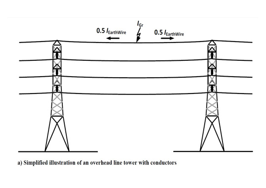
At the strike point, for instance on an overhead line earth wire as illustrated in Fig. 1, the injected current is divided equally between the earth wire ends connected to the towers. Therefore the impedance Z seen from the lightning strike is a parallel circuit of earth wires Zew and tower impedances Zt plus the ground impedance Ze as the tower footing is not remote earth – the reference point for the phase conductor voltage. Assuming that the lightning channel impedance is 3000Ω, the earth wire impedance 500Ω, tower impedances 200 Ω and ground impedance 50Ω, the equivalent impedance seen by the lightning strike calculates to 334Ω resulting in the injection of approximately 90% of the strike current at the strike point (Fig. 2).
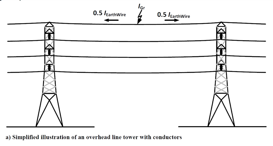
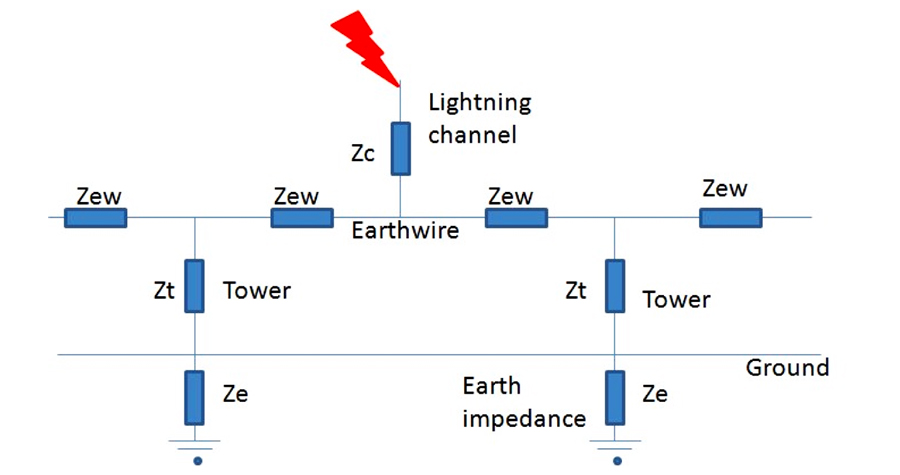
In round terms, therefore, a 30 kA strike to the earthwire will result in a 14 kA surge going in each direction towards the towers. The surge will travel to a point of impedance change (the pole top) at which there will be a reflected and transmitted component. The pole top junction has several routes available for the current and voltage waves and the surge current will split according to the inverse ratio of the surge impedances of the routes available – say ~200Ω down the tower route and ~500Ω for the continuing earthwire. The 14 kA surge will therefore split approximately 5/7 down the tower i.e. 10 kA. This goes on to the ground and generates a ROEP at the ground impedance.

Coupling Factor Between Earthwire & Phase Conductors
A lightning strike to the earth wire will induce a voltage on the phase conductors. This is beneficial since it reduces voltage stress on the tower insulators. The coupling factor CF can be derived from the following general relationship:
![]()
Electrostatic and electromagnetic couplings are calculated using the following simplified formula
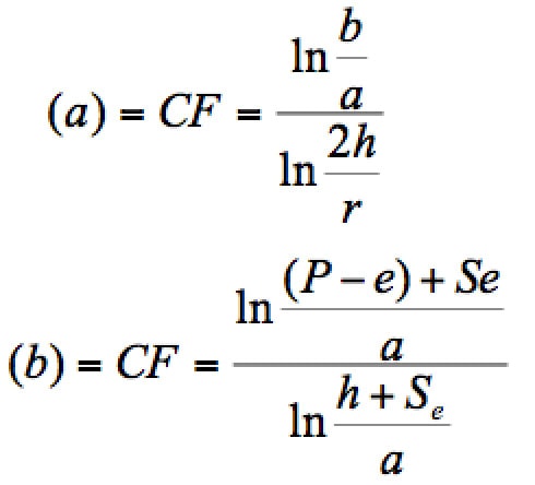 where:
CF Coupling factor.
a = distance earth wire to phase wire (m)
b = distance from phase B to image of earth wire in ground (m). Alternatively, for consistency with previous calculations the depth Se may be used.
h = height of earth wire above ground (m).
r = actual radius of earth wire (m).
The electrostatic calculations use an imaging technique for calculation where the image of a conductor is the same distance below the ground surface that the earthwire is above the ground surface. The electromagnetic calculations use conductor above ground height and a ground depth equal to the calculated depth of the image in the ground. The coupling factor of all phases of all tower types may thus be calculated. For a typical standard 400 kV tower with a single earthwire, the CF values would typically be around 0.2-0.3 for the upper phase, 0.11-0.18 for the middle phase and 0.06-0.12 for the lowest phase. These values are affected by ground resistivity and tower type.
Calculation of Cross-arm Voltage
The cross-arm voltage can be determined from the tower surge impedance, dimensions, crossarm positions and the tower footing voltage, which is obtained from the strike current and earthwire and tower impedance values. It is not intended here to go into the determination of the tower footing resistance/impedance as these are likely to be different.
Calculation of Insulator Stress
The stress across the insulator, Vins, is then determined from knowledge of the phase conductor voltage. The phase conductor voltage relative to remote earth will be the power frequency voltage plus the induced voltage, which comes from the earthwire surge. It is possible for back-flashovers to occur on any of the phases as although the cross-arm voltage will be lower for the lower phases, so will the coupling factor from the earthwire strike.
Effect of Tower Footing Resistance
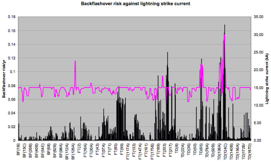
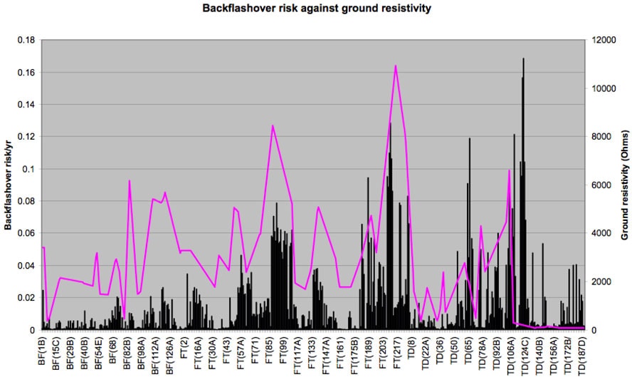
Looking at a standard 400 kV tower and the various parameters discussed in this paper, the stress across the phase insulators can be calculated. For the lowest phase if the tower footing resistance (TFR) is ~5Ω then with C~0.08, Vins will vary from 1.09 MV to 1.32 MV. As the 50% probability of failure is 1.4MV, there is a probability of around 10% that this insulator will flashover if the strike occurred at an appropriate point on the power frequency cycle. The utility may accept this rather than use TLAs. However, a substantial part of the Beauly Denny line is on granite with a ground resistivity of over 20,000Ωm and for several towers the TFR cannot be reduced below 100Ω unless several thousand pounds is spent. If R=100Ω, then the lowest phase will have a Vins of between 1.37 to 1.83 MV and thus an almost 100% probability of flashover. The utility choice is then between using TLAs on the lowest phases or spending a considerable amount of money on reducing earthing levels. It is thus possible to evaluate a backflashover risk per tower. Figs. 4.3 to 4.5 show the backflashover risk per tower against lightning strike density, strike current and ground resistivity.
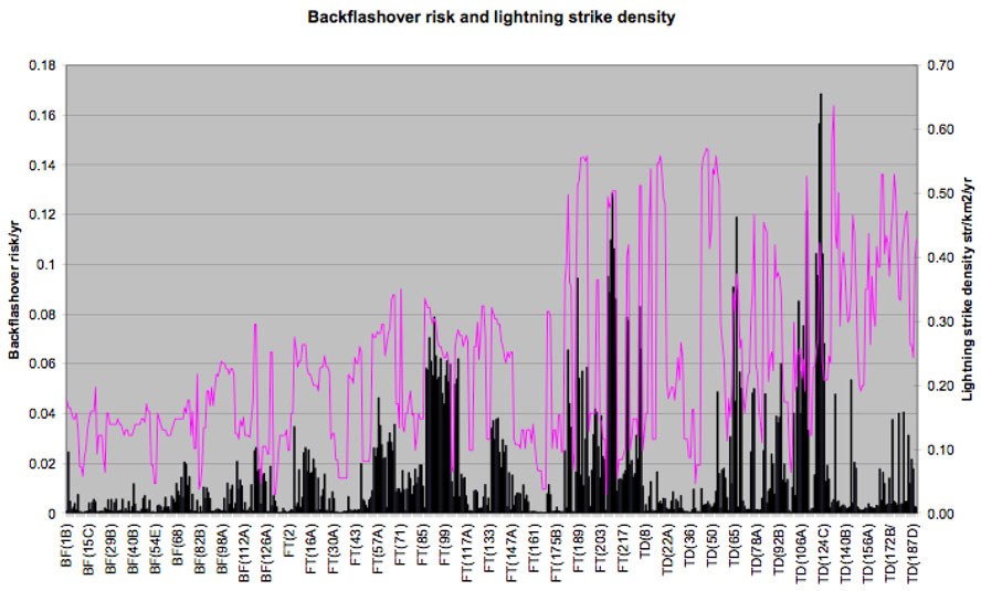
The lack of correlation with strike density is because other factors such as lightning strike current and ground resistivity can have a significant effect. There is mostly good correlation between high lightning surge currents and flashovers but in one case there appears to be little effect. This is because of the low lightning strike density. Fig. 5 shows a good correlation between high ground resistivity and backflashover rate.

Field Experience In South America
Placement of TLAs
As the Beauly-Denny line is still under construction, performance data is not available. However, data from Cigré concerning the Cambuci – Sto Antonio Padua 69kV and the Antamina 220kV lines in Brazil provides such data. Lightning has been reported as the major cause of non-scheduled outages in Brazilian’s power system, creating many issues and damages for power supply utilities and their consumers. Losses and damages in the Brazilian power supply utilities caused by lightning exceed an annual value of $350 million.
Installing one TLA on an individual tower reduces the probability of flashover (Fig. 6). This shows the effect on individual towers. While the lightning performance is improved, this improvement is restricted since surges will cause problems at neighbouring towers that are not protected. As can be seen, the improvement for one TLA per circuit is only around 30% and in some cases much less. If a second TLA is installed the improvement is only marginal.
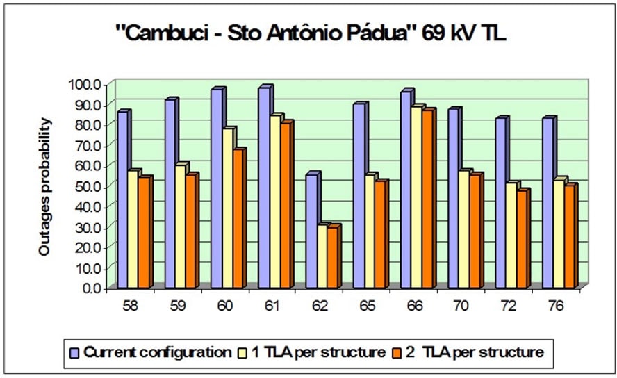
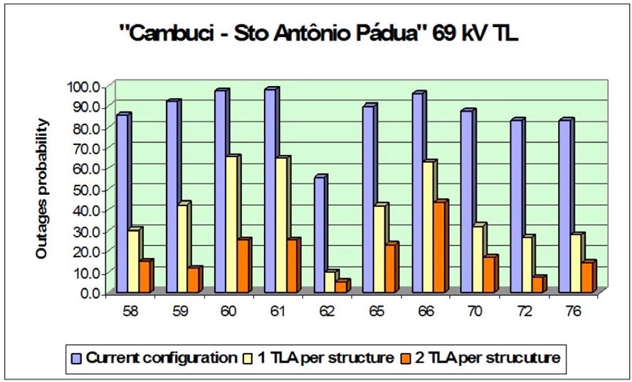
Fig. 7 shows the effect of applying TLAs on adjacent towers. The improvement now is commonly over 50% (on the same towers as Fig. 5.1) and the gain from the installation of a second TLA is significant – in some cases reducing the back-flashover rate to less than 10% of the original unprotected level.
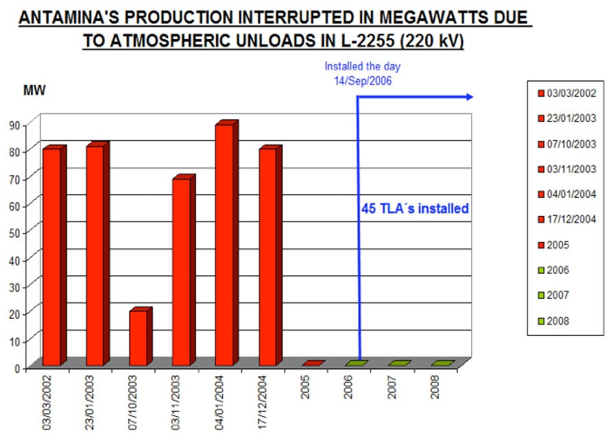
The Antamina Mine is located in the Antamina valley in the Andes Mountains in the Ancash region of north-central Peru and is fed by five 220 kV transmission lines located in regions with isoceraunic levels from 15 to 90 thunderstorm days per year. In the period from 2002 to 2006, 80 non-scheduled outages occurred due to lightning which affected the production processes on these 220 kV lines and other outages due to lightning also occurred on an associated 23 kV overhead shielded distribution ring network. From January 2006 till June 2007, approximately 450 units of class 2 line arresters were installed along the distribution network and 265 gapless transmission line arresters rated at 192 kV were installed along the sections of the two 220 kV transmission lines with the worst lightning performance. From October 2006 to February 2008, five outages due to lightning were recorded on sections of the lines which were not protected but no outages on the protected lines (Fig. 8).
Brazil’s transmission system has more than 3000 units of gapless line arresters installed along overhead lines from 34.5 kV up to 230 kV. Analysis and evaluation of lightning performance before and after the installation of line arresters have shown high effectiveness, with average indexes for the improvement greater than 70%.
Lightning Performance with TLAs
Lightning is the most frequent cause of transmission outage and service interruption in the United States, accounting for about 30% of all power outages, and resulting in economic losses approaching $1 billion annually. Reduction in earthing levels can achieve significant reduction in back-flashover rates but this can be very difficult and expensive in areas of high ground resistivity. In general:
• Typically not needed in all phases to get a significant reduction of backflashovers
• Areas with high tower footing resistance are first targets.
• The use of TLAs on adjacent rather than individual towers generally produces better results.
The best performance in reducing flashovers is to put TLAs on both circuits and all phases but this can be uneconomic. Two TLAs in one circuit and one TLA in the most exposed phase of the second circuit may give an even lower outage rate for the two circuits together and still get very close to zero risk for a double circuit tripping. Calculations are required to determine which are the most exposed phases.

Costs: Earthing Versus TLAs
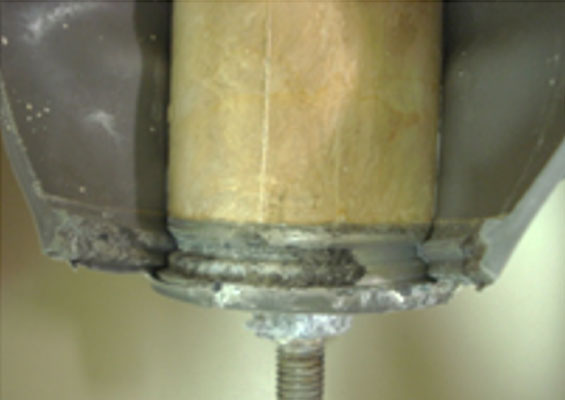
It is possible to calculate the minimum tower earthing level to reduce the back-flashover rate to a level acceptable to the utility. The cost of reducing the tower footing resistance to this target value can then be determined. Other factors to bear in mind are the possibility of copper theft, thereby increasing the resistance and back-flashover rate, and the failure rate of the arresters, thereby reducing the overall reliability of the line. Normally, this failure rate is well known in terms of substation arresters, but with TLAs there is the additional problem of conductor movement to deal with, whether this is due to vibration, galloping or simply excessive movement under high winds. Without these extra factors, it is a relatively easy calculation to determine whether earthing improvement or arrester use is more economic. However, lack of field-testing and necessity or otherwise of increased damping means that the mechanical reliability of TLAs cannot yet be established. If the TLA presence increases vibration levels, for example, then a shortened conductor life may result. Another aspect is the disconnection time related to the circuit breaker operation time. There is therefore a race between the line protection scheme and the TLA disconnector operation and this may vary from incident to incident as well as in different weather conditions. However, this is an electrical/mechanical balance situation that is not within the scope of this article.
Conclusions
There is a wealth of experience of TLA use in many countries, particularly in South-East Asia and South America. There is no doubt that significant improvements in the lightning performance of OHLs can be achieved with TLA use and that in areas of high lightning activity and/or high ground resistivities it can prove to be the most economic option. However, the effect of a significant weight on OHL conductor is not fully known, especially with regard to vibration and galloping scenarios. The disconnector time is also another area that needs to be considered in relation to the protection system used. It is possible to calculate the appropriate phases and towers that would benefit from TLA use and thereby focus TLA use economically to achieve the required performance level. However, the mechanical considerations of vibration and galloping and TLA effects on the OHL conductor are yet to be evaluated and testing in the field is recommended.