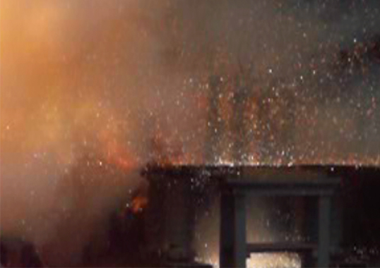
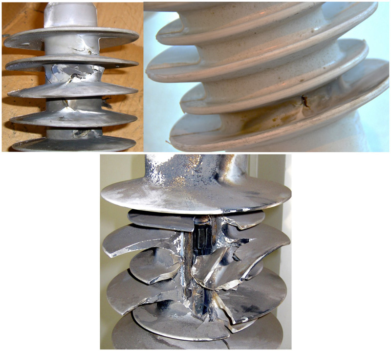
The failure of an arrester almost always results in a complete short circuit inside its housing. In most scenarios, failure occurs due to dielectric breakdown, whereby the internal structure has deteriorated to the point where the arrester is unable to withstand applied voltage, whether normal system voltage, temporary power frequency overvoltage (e.g. following external line faults or switching) or lightning or switching surge overvoltages. There are a variety of reasons why an arrester might reach such a state. This edited past contribution to INMR by now retired industry expert, Michael Comber, reviewed principal modes by which arresters can fail.

Moisture Ingress
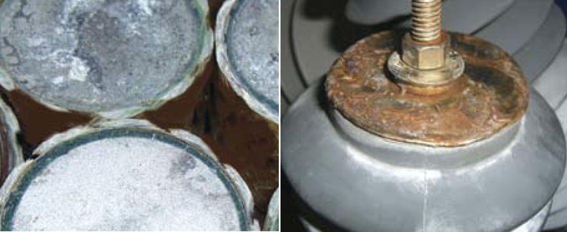

Perhaps the most common cause of arrester failure is moisture entering its interior. This implies that the arrester was:
• not well designed, or
• not properly manufactured, or
• damaged by some external force that compromised its sealing system.
While the underlying cause in each case may be the same, the way this progresses to eventual failure can vary significantly.
In the case of a hollow core arrester where there is gas space around the column of MOV blocks (typically dry air or nitrogen), even a tiny leak can result in what is referred to as ‘seal pumping’ due to pressure differentials. For example, during the day suns heats the arrester such that the internal pressure increases relative to ambient and outward gas leakage occurs. When the arrester cools at night, this process reverses, with internal pressure dropping below ambient and external air (with all its moisture content) being drawn into the arrester. Such a cycle can repeat itself over many days, months or even years before the moisture inside builds to the point where there is a problem with reduced dielectric integrity.
In a solid core arrester design (with little to no internal gas space) this process will not take place. However leakage can still occur through imperfect end seals. In this case, moisture ingress is more due to ‘wicking’ – a process whereby moisture gradually finds its way down through interfaces between the MOV blocks and the materials in contact with them.
The manner in which dielectric integrity is degraded due to moisture ingress can also vary. The mere presence of moisture, if concentrated only within the gas inside a hollow core arrester, will not have significant impact on dielectric strength. Rather, it is how this moisture interacts with internal surfaces and materials that becomes the issue. It has been noted, for example, that moisture related failures of porcelain-housed arresters tend to occur more in the evening than during the heat of day. This is attributed to accumulated moisture condensing on the inside walls of the porcelain when it cools after sunset. Electrical strength across the wall is then progressively reduced until internal flashover occurs from end to end.
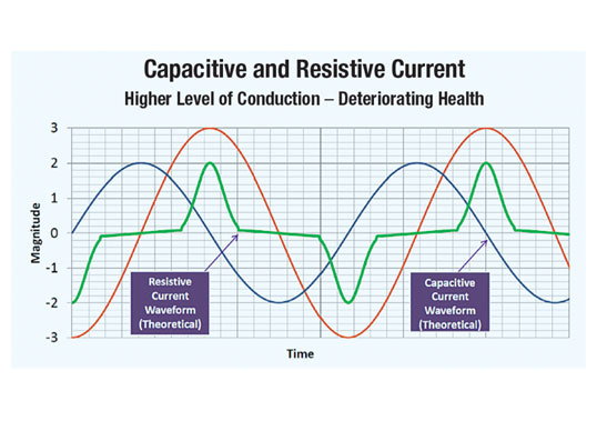
Moisture will typically not condense on the MOV blocks of an energized arrester because these generate enough heat to keep their temperature slightly higher than that of the surrounding gas. However, if the material used to coat or collar the blocks is hygroscopic, it can absorb moisture thereby causing some blocks to become more conductive on their outer surfaces. This essentially shifts voltage to other blocks and leads to higher conducted currents, external to some blocks but internal to others. Ultimately, the complete stack can no longer withstand the applied voltage. (Note: this scenario can be avoided by ensuring only non-hygroscopic collaring materials, such as glass, are used.) In the case of solid core arresters, moisture that has wicked into internal interfaces along either a portion or the complete length of the arrester can result in dielectric breakdown and failure.

Temporary Overvoltage (TOV)
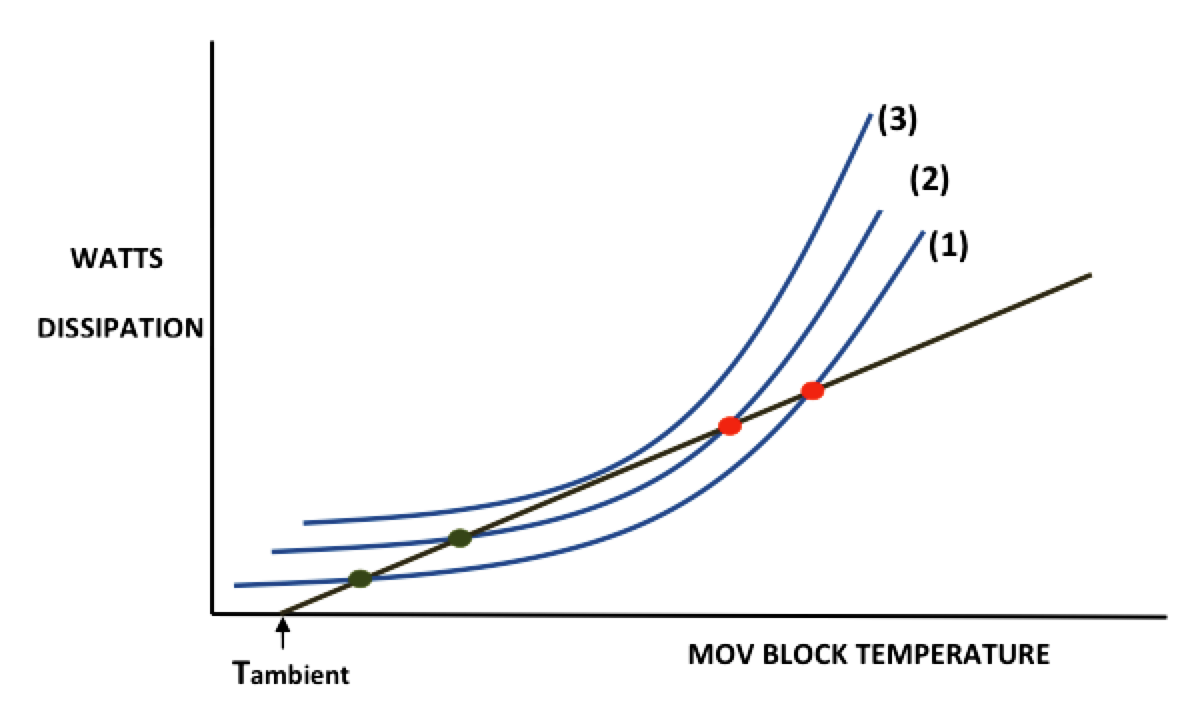
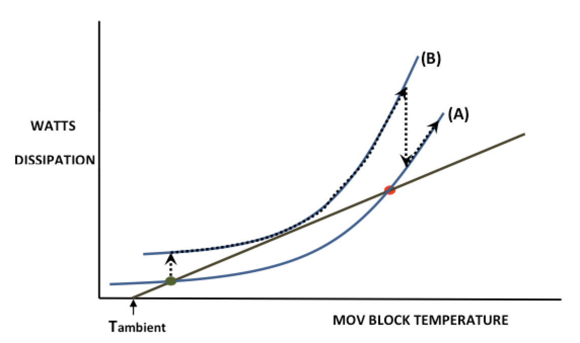
Under normal operating conditions, which see the arrester energized at its maximum continuous operating voltage, Uc, the temperature of the MOV blocks rises only slightly above ambient. A point is then reached where the incremental heat generated is in equilibrium with the heat the arrester dissipates into the surrounding air. This represents the arrester’s normal thermal stability operating condition, depicted by the green dot on curve 1 of Fig. 1. Here, the blue curves represent power losses of the MOV blocks as a function of block temperature and the dark tan line represents the heat that can be dissipated from the arrester assembly, also as a function of block temperature. If the power frequency voltage across the arrester increases (e.g. due to a system disturbance, fault or switching operation), the MOV blocks conduct more current and begin to heat up.
As long as the overvoltage is below some critical limit, a new thermally stable operating point will be reached, albeit at a higher MOV block operating temperature, as depicted by the green dot on curve 2. However, should the overvoltage be of sufficient magnitude, the heat generated by the blocks remains greater than the unit can dissipate. A potential thermal runaway situation will then occur, as depicted by curve 3.
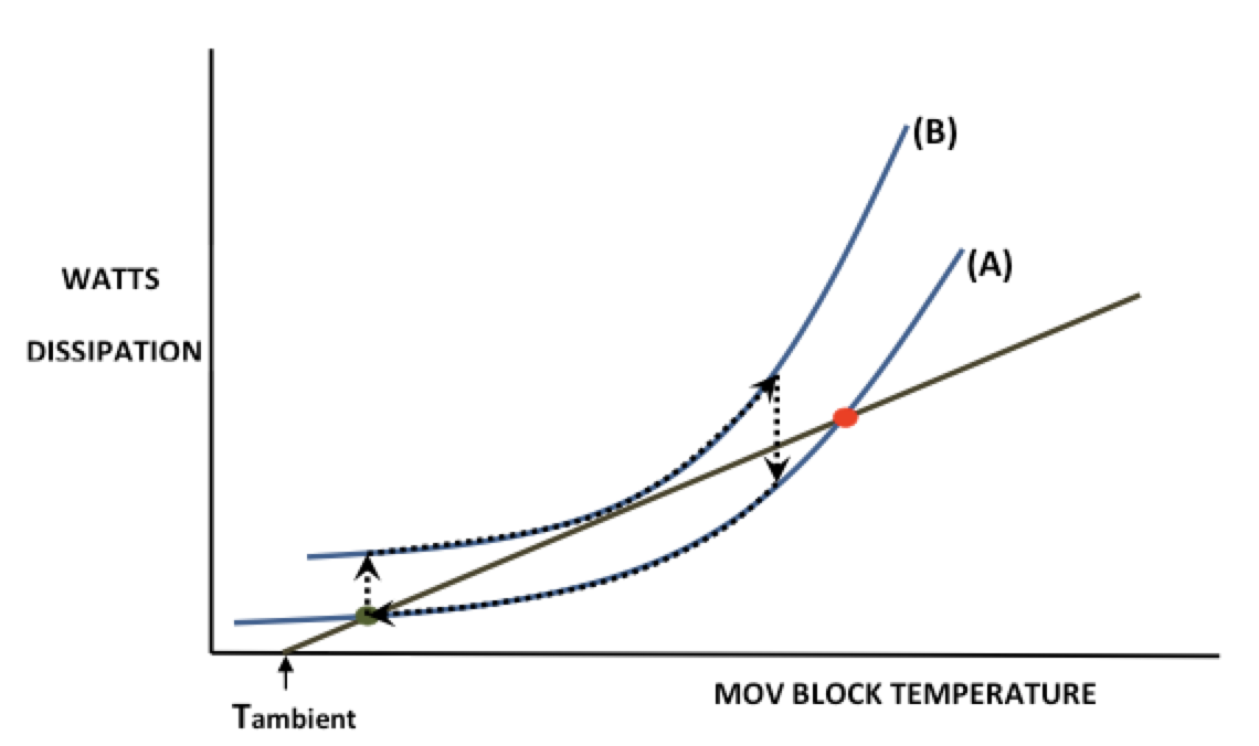
Should voltage return to normal (i.e. to the MCOV) before critical block temperature is reached, the arrester will remain thermally stable and will eventually cool to its initial condition, as depicted in Fig. 2. Here, curve A represents the conditions for normal operating voltage (i.e. MCOV) and curve B the conditions for an elevated voltage that can potentially lead to thermal runaway – even though this is avoided because voltage returns to normal before the critical temperature is reached.
On the other hand, if the overvoltage continues beyond the point at which critical MOV block temperature is reached, the temperature of the blocks continues to rise even if voltage returns to MCOV, as depicted in Fig. 3. In such a case (i.e. thermal runaway), the blocks eventually become so conductive that they can no longer support even MCOV and will be short-circuited, resulting in arrester failure.
Ageing of MOV Blocks
In the early days of metal oxide arresters during the mid to late 1970s, MOV blocks from all manufacturers exhibited some degree of ageing, whereby their power dissipation at any given voltage increased slowly, but continuously, over time. The resulting impact on arrester performance would be similar to that described for TOV – namely after some time in service, the power (heat) generated by the blocks would be basically similar to that resulting from a TOV occurring when the blocks were new.
As time progressed, the heat generated would be equivalent to that from a higher TOV on blocks in their new condition. Ultimately, the heat generated reached a point where no stable operation could be maintained, as depicted by curve 3 in Fig. 1. The blocks would then experience thermal runaway, just as if exposed to a sufficiently high, sustained TOV when in their original new condition.
This ageing characteristic of blocks was recognized early on and was addressed in ANSI/IEEE as well as IEC test standards by means of accelerated ageing tests. In these tests, sample blocks were subjected to MCOV for 1000h while maintaining block temperature at 115°C and it was considered that this was equivalent to 40 years service at 40°C. If at the end of 1000h the power dissipation was higher than at the start of the test, parameters for other duty tests had to be adjusted to account for this increase. The clear implication was that arresters passing the tests would be good for at least 40 years of service (provided of course that they operated within the specifications). With subsequent major improvements in processing technology, MOV blocks produced these days exhibit a characteristic whereby power dissipation actually decreases over time at any given voltage. This implies that they become more rather than less thermally stable during service and therefore are unlikely to cause arrester failure due to ageing.
Thermal Runaway from Surge Duty
The surge duty referred to here is that resulting from relatively high current surges due to lightning, switching of long lines or capacitor banks. Some of these may have very high amplitudes but relatively short duration (e.g. lightning surges), while others have much longer duration but with significantly lower amplitude (e.g. switching surges). Still, all have a charge content that, when passed through an arrester, results in a certain amount of energy absorbed by the blocks. This absorbed energy causes almost immediate adiabatic heating. MOV blocks typically have a specific heat capacity of about 3.3 J/cm3/°C, meaning that they will sustain a temperature rise of about 10°C for every 33 J/cm3 of energy (assuming this energy is input rapidly).
If the input of energy is excessive, the resulting temperature rise of the blocks may be such that the arrester is pushed into a thermal runaway condition. For example, with the arrester operating according to curve 1 in Fig. 1, the stable operating temperature will be that depicted by the green dot. If the temperature of the blocks is raised quickly (as a result of energy absorption) so that it becomes higher than depicted by the black dot on the same curve, then the arrester will not recover from this event and go into thermal runaway, as described earlier for a situation of prolonged TOV.

Damage to MOV Blocks From Surge Duty
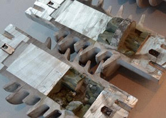
One manifestation of the energy absorbed by the MOV blocks is rise in their temperature, as discussed above. However, if the energy is of sufficient magnitude and deposited over a relatively short period of time, the blocks can become irreversibly damaged.
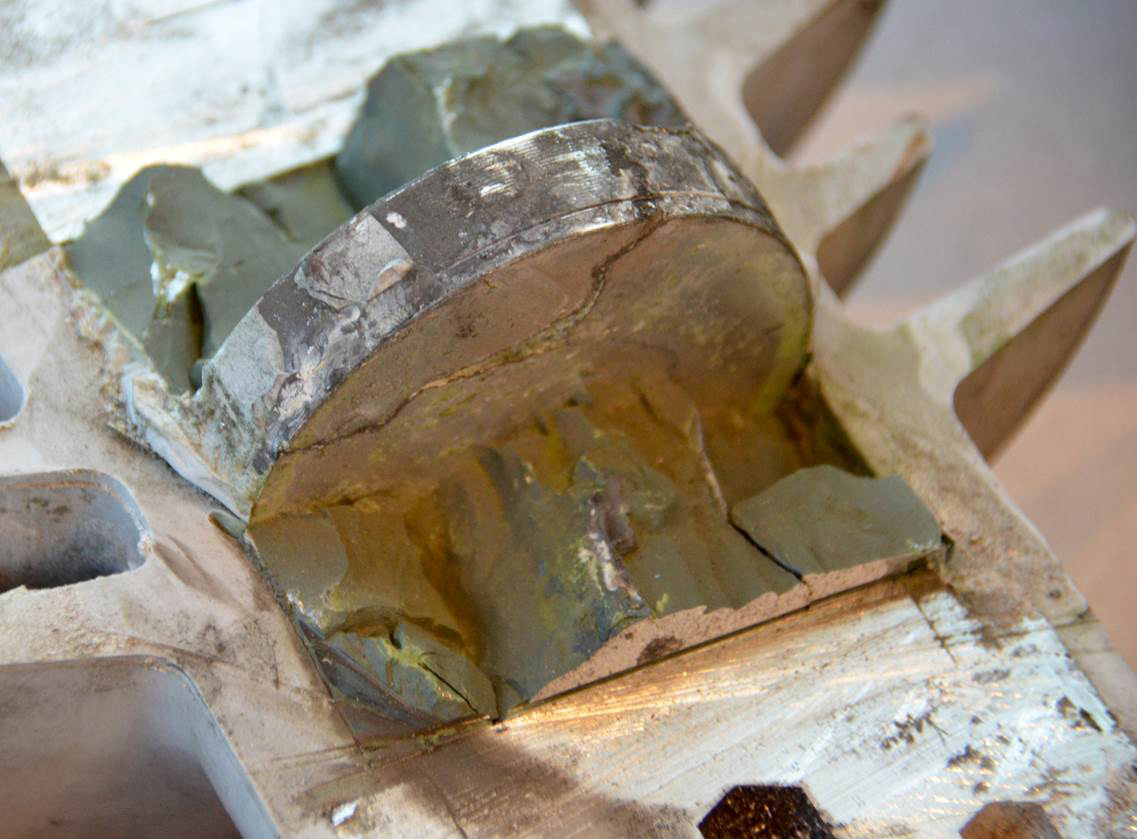
For example, the resulting thermo-mechanical shock could cause them to crack into two or more pieces. In other cases, varistor blocks can be punctured in localized areas, either partially or completely through their body. In yet other cases, a pinhole type failure can occur at the edge of the block, possibly causing material to be removed from its outside surface. Typically, each such type of damage is accompanied by degradation of the block’s electrical integrity, manifest either by its inability to sustain another energy event without electrical breakdown or by a reduction in its capacity to support normal operating voltage. Both situations can sooner or later result in complete arrester failure.