Although growing demand for power and quality has resulted in the need for increased transmission capacity, erecting new overhead lines in many countries is often constrained by public opposition and environmental regulations. It then becomes necessary for power utilities to look for other opportunities, such as uprating existing systems. At the same time, even when issues of public acceptance are resolved, line designers these days and are still requested to create new concepts to reduce footprint and visual impact of structures. In this regard, compaction and uprating often require reconsidering tower designs that have remained more or less unchanged for decades. Fortunately, progress in composite insulator and surge arrester technologies has allowed compact lines to become a realistic alternative to standard designs, offering more discrete and aesthetic structures. Moreover, given the operating principle behind surge arresters, structure clearances and insulator arcing distances can be significantly reduced while also improving availability. In this regard, integration of arresters can help advance the concept of a compact line.
This edited contribution to INMR by Bastian Robben and Maja Jolic at Siemens Energy Global in Germany reviews opportunities to optimize transmission line capacity as well as power quality. It also addresses some of the technical challenges that must be resolved when implementing compact power system solutions.

Mitigating Overvoltages Using Surge Arresters
Fig. 1 shows the types of overvoltage that can occur in a high voltage power system (red curve) versus their duration and compares these to typical equipment and arrester withstand voltages (blue and green curves respectively).
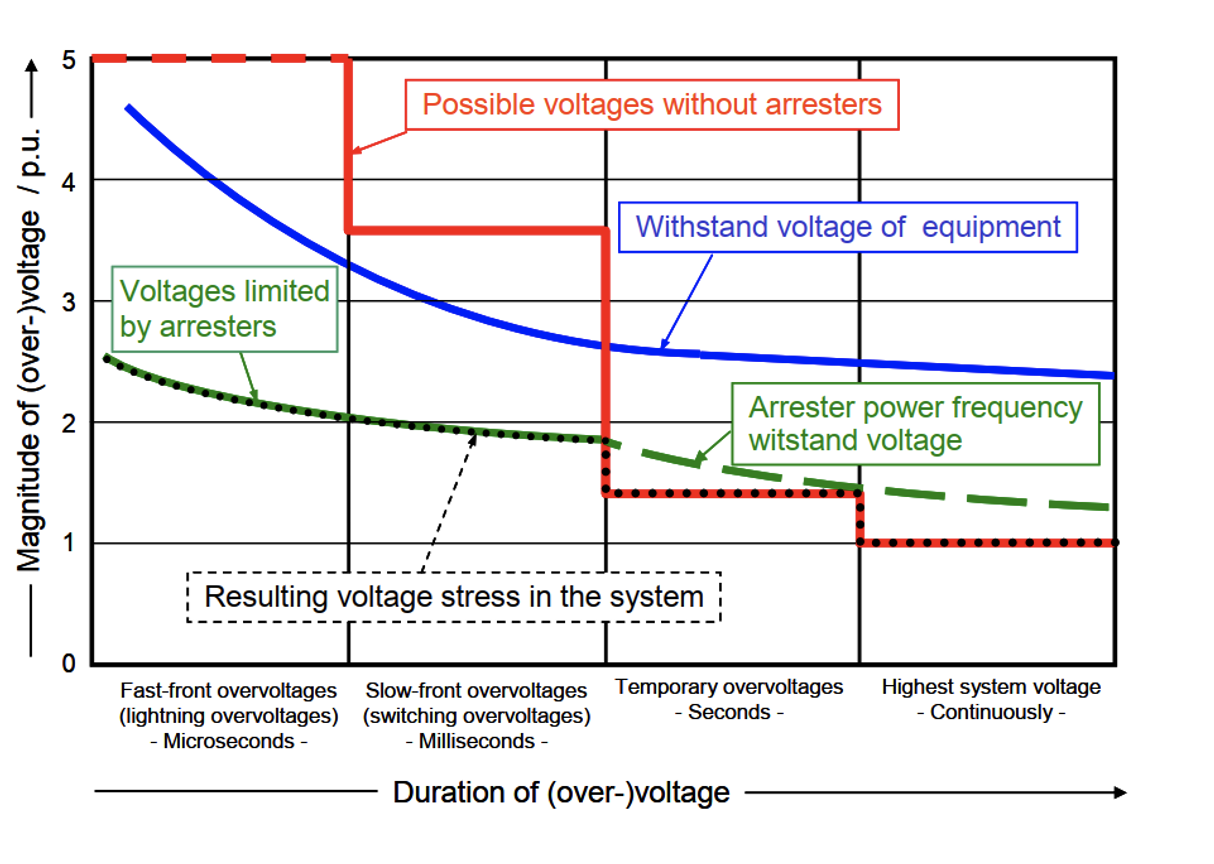
As evident, the insulation withstand voltage of substation equipment is significantly exceeded during lightning or switching overvoltages. With application of surge arresters, however, these overvoltages can be safely reduced. Indeed, conventional application of station class arresters aims to protect costly substation assets such as transformers and gas-insulated switchgear.
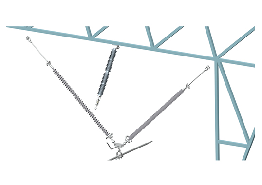
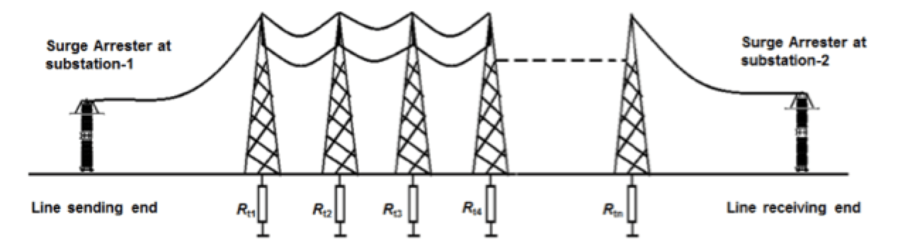
By contrast, application of line surge arresters (LSAs) serves an entirely different purpose, namely preventing flashover of insulator strings along a transmission line due to lightning strike. When installed on multi-circuit transmission lines, LSAs offer an excellent solution to eliminate all possibility of double-circuit failures. They can also be used on EHV lines to control switching surge factors. Up to now, the main area of application for LSAs has been as a retrofit to improve lightning performance of existing lines. Such applications require analyzing line parameters and investigating environmental conditions in order to optimize configuration as well as effectiveness. Fig. 2 depicts a schematic of a shielded transmission line equipped with LSAs. These are installed in parallel and next to insulator strings to prevent shielding failure should a lightning stroke hit the phase conductor directly.
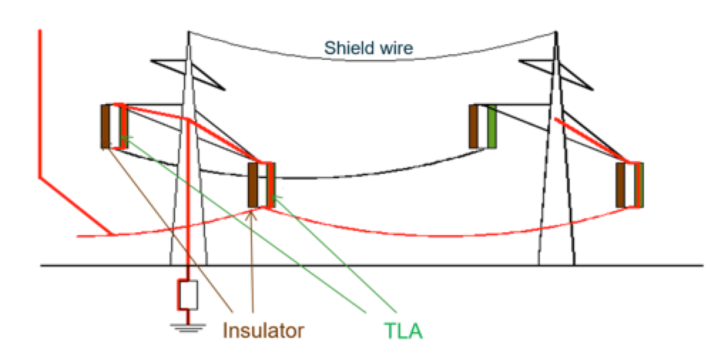
There are the two basic scenarios to describe flashovers due to lightning: direct flashover (also known as shielding failure); and backflashover, if a lightning stroke hits the shield wire or tower top. Insulator backflashover rates can be effectively reduced for shielded overhead lines located in areas of high lightning activity or where there is poor footing resistance. For example, arresters can be placed on all phases or, alternatively, only on the phase(s) with lowest coupling factor to the shield wires (normally the bottom phase in areas with high footing resistance). In such situations, it is important to apply arresters not only on structures in areas of high footing resistance but also on one or two of the structures with good (i.e. low) footing resistance located right next to those having high footing resistance. This will prevent flashovers on low resistance structures caused by arrester operation on those structures with high footing resistance. The higher the footing resistance, the higher the energy absorbed by each individual LSA.
Direct flashover occurs when a lightning stroke hits the phase conductor. Insulator flashover from ‘shielding failures’ are observed mostly on unshielded transmission lines but also occur infrequently on shielded lines that still experience direct lightning stroke to the high voltage conductor. Direct lightning strokes to phase conductors will occur far more frequently in the case of unshielded transmission and distribution lines than for properly shielded lines since these lines are not protected against lightning. In such cases, line arresters can be used to address shielding failure flashover by applying arresters on the exposed uppermost phases.
Other cases of system flashover induced by lightning strokes are observed on multi-circuit towers, such as those with an underbuilt distribution line, or on double-circuit transmission lines. The latter scenario generally has severe impact on the entire transmission system. Line arresters can be effectively used on double-circuit transmission lines and are installed on all three-phases of one circuit to prevent risk of double-system failures. This approach can be applied for all system voltage ratings, including EHV.
In cases where a distribution line shares a tower or pole with a shielded transmission circuit, underbuilt distribution conductors are not likely to be struck directly since they are shielded by the transmission circuit above. However, the distribution line is still prone to backflashovers because of the weak coupling between distribution conductors and shield wires. Insulation strength on the distribution line is also lower than for the transmission line. Once a distribution conductor flashes over, coupling to the transmission conductors will increase and minimize risk of a backflashover on the transmission circuit. In this regard, the lightning performance of the transmission circuit may improve but at the expense of the underbuilt distribution circuit. This problem can be reliably avoided by applying line arresters on at least one of the three phases of every tower or pole on the underbuilt distribution circuit.
Two different designs of LSAs are available, both with relative advantages and drawbacks:
• Non-gapped line arresters (NGLAs), also called gapless; and
• Externally gapped line arresters (EGLAs).
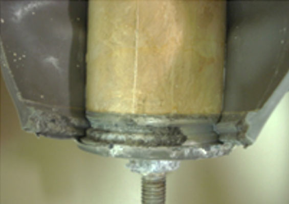
Non-gapped line arresters, as with a station surge arrester, have a direct connection to the high voltage conductor and are grounded to the tower on the other side (see Figs. 3 and 4). Unlike a substation, which cannot be operated without station class arresters due to the risk to costly assets, a transmission line can be operated without LSAs. Given this, NGLAs are equipped with a device that immediately operates and disconnects the LSA from the system voltage in case of thermal overload or arrester fault. This allows the affected overhead line to be re-energized and operated until replacement can be scheduled.

Externally Gapped Line Arresters
Externally gapped line arresters (EGLAs) are defined in IEC 60099-8 as ‘a lightning protective device consisting of two individual components – an active part called series varistor unit (SVU) representing the surge arrester part and an external gap in series’.
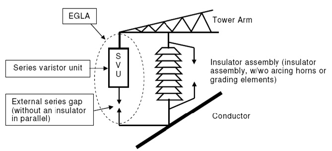
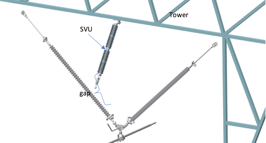
The main difference between an NGLA and an EGLA is the external series gap that isolates the SVU from the system, as shown in Fig. 6. The specific purpose of a gapped LSA is to handle lightning overvoltages and extinguish the arc between the electrodes of the series gap within a half-cycle of the system’s power frequency voltage. The surge current that flows as a result of a controlled flashover in the gap is referred to as ‘follow current’ and is the sum of the current flowing through the SVU’s metal oxide varistors and the pollution current on its housing. Since the metal oxide varistors limit follow current to a level of only several amperes, the ignited arc is extinguished and interruption of follow current acts within some milliseconds. There is no earth fault in the system and hence no necessity for operation of the line breaker to eliminate the failure.
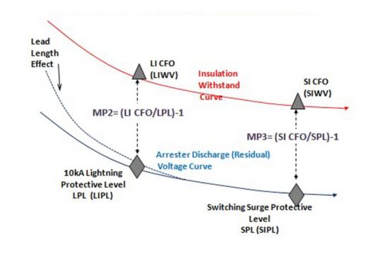
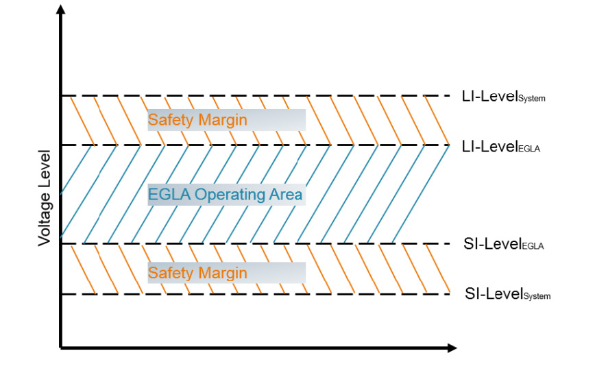
According to IEC 60099-8, energy ratings of MO varistors are tested with a lightning discharge test to verify repetitive charge transfer rating or Qrs. Moreover, in the highly unlikely event of EGLA failure, the series gap must withstand switching overvoltages of the system in order to be able to re-energize the transmission line. For this purpose, switching withstand tests on gaps are performed with a shorted SVU and under wet conditions to verify that the transmission line can continue to be operated, even with a failed EGLA. Fig. 7 shows where the EGLA’s operational area is located, between the lightning and switching levels of a system.

Dimensioning of the EGLA gap relates specifically to lightning and switching voltages. Maximum gap distance is limited by minimum lightning impulse flashover voltage of the insulators while minimum gap distance is limited by the transmission line’s maximum switching impulse withstand voltage.
Reduction in insulator string length and consequently tower height can best be achieved using EGLAs due to their relatively compact design compared to NGLAs. Moreover, since an EGLA is not continuously energized, its SVU requires less volume of MO varistors, which is an advantage in terms of lower weight as well as less work needed to install and maintain. Furthermore, the substantial reduction in material allows for a more compact size as well as better integration on the tower along with a wider range of installation options. An NGLA, by contrast, is of much larger size due to its disconnector and associated ground lead. This risks short-circuiting subjacent phases on the tower if falling to ground during an arrester overload (i.e. triggering of the disconnector).
Deciding on the correct configuration of an EGLA for each application includes defining its SVU ratings (i.e. energy rating, residual voltage, arcing distance), dimensioning the gap distance with respect to lightning and switching voltages and selecting a suitable mechanical design that usually differs with each installation option. Engineering aims to optimize integration of the EGLA onto a structure since it can be installed on cross-arms, on the structure itself or directly on the insulator string. The main requirement is to maintain a stable gap distance, even under conditions of line vibration and galloping. New transmission lines generally allow more installation options than when retrofitting EGLAs onto existing lines. The main factors in optimal dimensioning of reduced insulator arcing distance are minimum creepage distance and lightning impulse withstand voltage. The higher the system voltage, the more important switching surges become, especially above 300 kV.
Reducing Clearances Using EGLAs
The length of an insulator string is defined by its minimum arcing distance, which is calculated based on required maximum lightning and switching impulse withstand voltages. But combining an insulator string with an EGLA changes this conventional dimensioning approach such that arcing distance or lightning impulse withstand voltage of a string are no longer the decisive criteria. Rather, this becomes the lightning impulse sparkover voltage of the EGLA’s air gap. The smaller the gap and the lower the operating lightning sparkover (protective) voltage of an EGLA, the shorter will be the arcing distance needed for an insulator string – and also the shorter its required length. Moreover, the lower limit of gap distance changes with required switching impulse voltage.
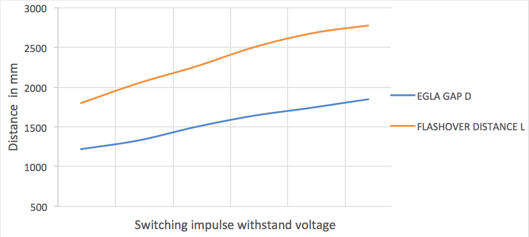
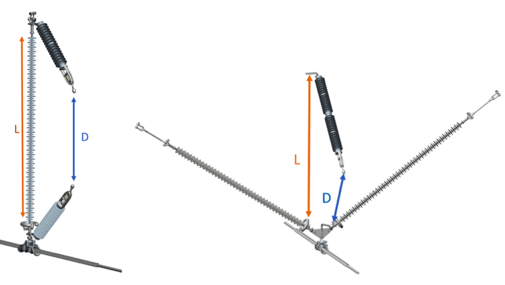
Fig. 9 illustrates the correlation of EGLA gap size (‘D’) and insulator arcing distance (‘L’) based on years of testing experience. The amplitude and shape of these curves depend on configuration of the insulator assembly as well as on the shapes of the EGLA’s electrodes. Fig. 10 shows examples of insulator assemblies combined with EGLAs.
In order to obtain the most compact solution possible, required switching impulse withstand voltage must be available. The lower the switching surge factor, the more compact a system can become. A typical 420 kV transmission line in Germany, for example, has a switching impulse withstand voltage level of 850 kV while the insulators have an arcing distance of 3 m. In combination with the EGLA, the arcing distance of the string can be reduced to 2.7 m – a reduction of 10%. This reduction factor applies to all circuits and all phases of any specific line, as seen in Fig. 11.

Simulation of Switching Performance of Overhead Lines
Reduction of switching surge factor on a transmission line is essential to achieve efficient compaction or uprating of the line since it is the dimensioning factor for the lower limit of the EGLA gap distance. To determine the switching overvoltages that occur, the performance of an overhead line was simulated with a simulation tool (Sigma SET) and using the following parameters:
• Transmission line length: 100 km
• Line span length: 365 m
• Basic insulation level of line insulator: 1425 kV
• Closing time of 420 kV circuit breaker: 65 ms
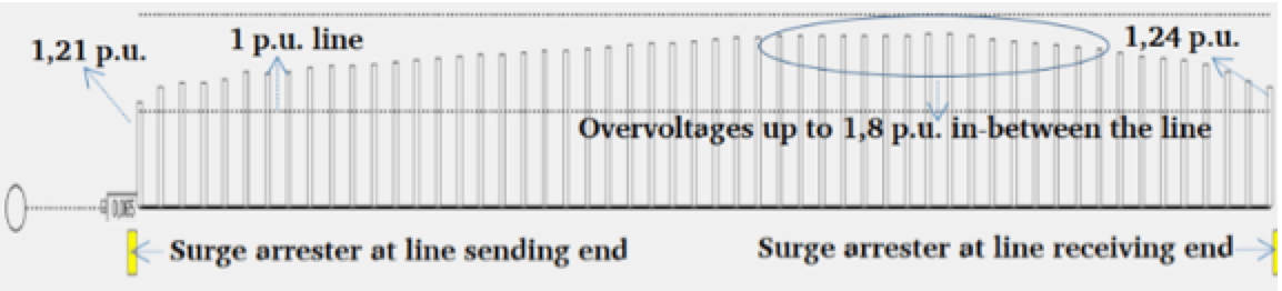
This simulation resulted in a switching overvoltage of 3.12 p.u.
![]()
for the transmission line in this example, without surge arresters at the substations. With station arresters at both the beginning and the end of the line, switching overvoltage can be limited to 1.84 p.u.
The safety margin results in 7.8% based on the factors Sigma and X, according to IEC 60099-8:
With Sigma = 6% and X = 1.3
Given a switching impulse withstand voltage of 664 kV, EGLA gap distance is about 1.36 m. The correlating arcing distance of the insulator string is 2.1 m – a length reduction of 30% compared to the initial arcing distance of 3 m on a standard 420 kV transmission line. In theory, this means that strings typical for 245 kV can be used for the 420 kV system.
Depending on system parameters such as as line length, short-circuit ratings and voltage levels, switching surge factor is generally mitigated and reduced with the help of closing resistors and/or shunt reactors. Station class arresters in the substation can also be improved by reducing their residual voltage and increasing their energy handling requirements.
The most cost-efficient method remains application of NGLAs at a few locations along the transmission line. Simulations must be carried out to define their energy rating and exact location.
In this specific simulation, it was assumed that line length is only 100 km which is the limiting the factor for switching surges. Typical transmission lines for 245 kV and above, however, are generally much longer and higher switching surges can be expected. As such, NGLA application for switching surge control becomes even more justified for longer transmission lines.

Further Challenges
There are clearly opportunities to review conventional ratings and standard designs to achieve line compaction and line uprating. The potential of using EGLAs to decrease arcing distance of insulators and to increase energy availability is obvious. Yet several important aspects have to be considered and investigated before such solutions can be implemented.
1. The reduction in insulator arcing distances involves increase in creepage factor, e.g. by using new shed profiles and larger shed diameters.
2. Existing compact and uprated line designs demonstrate the important role of insulated cross-arms and specific designs of line post insulators to suppress horizontal line movement.
3. Reducing clearances and increasing system voltage result in higher corona activity that needs to be controlled and suppressed. Innovative insulator string designs and specific hardware components should be considered in this regard. Moreover, new high temperature conductor technologies allow for special designs of clamping system to carry higher current loads. These latest developments should ideally be integrated into the design stage to optimize compact line solutions for each user.
4 In some countries, minimum clearances are regulated and the same ratings have been applied for decades without consideration to obtaining lower values by application of line arresters. The protection level of metal oxide varistors is a safe method to reduce clearances but unfortunately not always fully understood. Technical committees and working groups involved in standardization should therefore work more closely with line designers and arrester manufacturers to offer greater flexibility when it comes to regulation of electrical clearances.

Conclusions
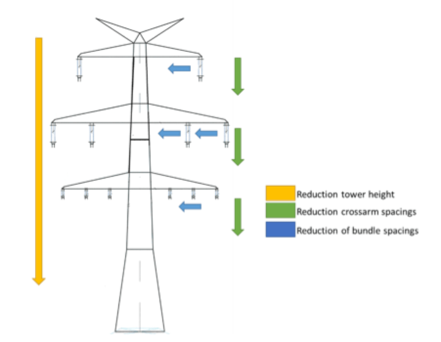
Reducing clearances of insulator strings and transmission lines with the help of line surge arresters offers great potential in line compaction. Simulations show that it is technically feasible to reduce the clearances and dimensions of a conventional 420 kV transmission line by up to 30% using EGLAs combined with appropriate station class arresters. EGLAs installed on each tower and each phase not only help optimize design and reduce clearances but also offer reliable protection against lighting outages. The concept of downsizing a line’s geometry also applies for line uprating in addition to line compaction since the basic principle is the same. For example, the approach presented above can be used to uprate an existing 245 kV line to a new 420 kV system as a retrofit application. Along with any necessary modification in insulators strings, this can result in a significant increase in power capacity with no need to modify structures, clearances or existing right-of-way. The result is reduced environmental footprint and less visual impact in any landscape.
It has been demonstrated in the literature that application of EGLAs is the most appropriate solution for reducing lightning outages. Moreover, arcing distance of insulator strings can be reduced to a minimum if insulation coordination is verified between EGLA protection level and insulator withstand level. The smaller the EGLA air gap, the more compact the clearances will be. Depending on voltage levels, generally 245 kV and above, and on line parameters such as length, switching surge factors become critical. Here, application of NGLAs is a simple and efficient solution to reduce switching surges and minimize compaction. Switching studies are often required in this case since reclosing operations are not sensitive for conventional designs of 245 kV systems and higher. NGLAs installed at only a few locations along the transmission line represent a moderate investment yet yield outstanding results.
Several utilities, surge arrester manufacturers, line designers and engineering consultants are currently working on feasibility studies. Pilot projects will be implemented, beginning in developed countries where existing networks need to be updated. Innovative solutions will have to be developed, especially in places such as Europe, where space for power corridors is limited. Similar applications are already in service, for example on catenary systems under bridges and in small tunnels. Further challenges related to creepage distance, RIV/corona, insulator design and mechanical aspects will also have to be investigated, analyzed and solved. Improved co-operation between arrester manufacturers and line designers will also be necessary to rapidly enter a new era of optimized transmission lines.
References
[1] V. Hinrichsen, ‘‘Metal-Oxide Surge Arresters in High-Voltage Power Systems-Fundamentals’’, 3rd Edition, 2011, Siemens AG, Berlin/Germany.
[2] IEC standard 60099-5, ‘‘Surge arresters – Part 5: Selection and application recommendations’’, 2nd Edition, 2013
[3] CIGRE 440 – Working Group C4.301: “Use of Surge Arresters for Lightning Protection of Transmission Lines”, December 2010
[4] J. Woodworth, ‘‘Externally Gapped Line Arresters (EGLA)’’, Arrester Facts 004a, 2008. Available from: <http://www.arresterworks.com/ArresterFacts_files/Arrester%20Facts%20004a%20-%20Externally%20Gapped%20Arrester.pdf [Date taken: 26 October 2014]
[5] IEC 60099-8, Surge Arresters – Part 8: Metal-oxide surge arresters with external series gap (EGLA) for overhead transmission and distribution lines of a.c. systems above 1 kV, International standard, Edition 2.0, 2017-11.
[6] Faisal Farooq: Lightning and switching performance of a 420 kV transmission line by using surge arresters; 2014 Siemens AG, Berlin/Germany
[7] Innovative Tower Solutions & Line Uprating, Konstantin O. Papailiou, INMR website