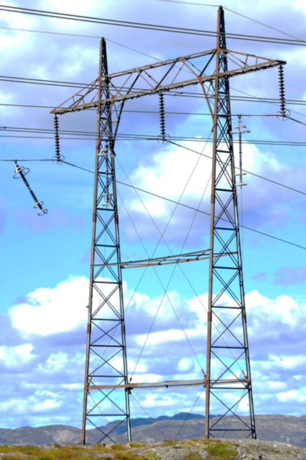
Many transmission line surge arresters (TLSAs) are suspended from phase conductors, adding mass that creates a new mechanical node between insulator suspension clamps and Aeolian vibration dampers. Such placement interferes with damper performance and could shorten conductor service life.
This edited past contribution to INMR by T&D expert, Dr. William Chisholm, discussed alternative mitigations, which include re-positioning dampers, inspecting more frequently or selecting other installation configurations. It also offers a case study that illustrates how these factors were considered during installation of TLSAs on a 230 kV line as alternative to continuous counterpoise.

The first successful lightning surge arresters for electric power systems used hollow ceramic insulators, filled with silicon carbide blocks to provide non-linear voltage limiting electrical characteristics. The silicon carbide arresters had internal components to quench and interrupt AC power system follow current that normally keeps flowing through a flashover arc. The hollow ceramic insulators were sealed with metal plates, providing over-pressure protection but also allowing long-term moisture ingress that shortened service life. These arresters were used mainly for protection of equipment. Two separate technologies converged to improve the reliability and service life of arresters:
• The non-linear electrical performance of metallic oxide varistor (MOV) materials was superior to silicon carbide. This technology was patented by Matsuoka, working at Matsushita Electric Company, in 1970 and had displaced silicon carbide in many applications by 1980.
• Polymer rubber materials, including ethylene propylene diene monomer (EPDM) and long chains of polydimethylsiloxane (silicone), protected the MOV elements against moisture while reducing weight and cost, compared to ceramic housings. The industry wide substitution of polymer for porcelain took place over the brief period from 1987 to 1995.
These improvements made it practical to use transmission line surge arresters (TLSAs) to improve lightning performance by applying them at some or all insulator positions, as well as at equipment or line terminals. Electrically, TLSAs using MOV materials have been successfully installed to limit transient overvoltages on line insulators for more than 30 years. For example, successful application of TLSAs on an unshielded 230 kV transmission line since 2001 used arresters with 60 mm block diameter. Exper¬ience with improving MOV technology allowed reduction in block diameter from the initial 61-76 mm to only about 40 mm for shielded lines, with overhead ground wires (OHGW) that limited their energy duty by diverting a large proportion of current to ground. Further reduction in cost and increase in performance has been achieved using a direct mold silicone construction that eliminates internal air spaces. Originally developed as components to be retrofitted to existing lines, TLSAs have now become an important design and mitigation alternative to investment in extensive grounding systems for new line designs. One case study set out the decision criteria leading to fitting of TLSA to all three phases of a 230 kV transmission line during construction, as an alternative to using continuous counterpoise in an area where rock resistivity was extremely high.

Mechanically, however, TLSAs have demonstrated in-service problems, the most common being rapid degradation of flexible leads and their terminals. Once a lead breaks away or pulls out from the tower or the bottom of an arrester, its uncontrolled motion in the wind can reduce electrical clearances. Rigid configurations, including the external gap EGLA type, do away with flexible leads and offer longer service life.
Unfortunately, many TLSA installations have been made in ways that affect or even completely defeat the mechanical protection given by Aeolian vibration dampers. Aeolian vibration is a low amplitude high frequency vertical vibration that accumulates millions of stress cycles. This is particularly a concern for lines that operate over a wide temperature range, e.g. -40 to +40°C. At low temperature, high conductor tension especially needs effective vibration control. Conductor damage has been associated with installation of components that have the same weight and size as TLSAs, notably aircraft marker balls, anti-galloping detuning pendulums and spacer dampers. Galloping is large amplitude low frequency oscillations involving complex vertical, longitudinal and torsional motions that accumulate thousands of stress cycles ad are common when there is an ice layer on conductors. Rocking motion along the line direction is a concern, especially if a resonant frequency of the span is synchronized to the pendulum frequency of the arrester itself. An arrester installation that causes galloping is theoretically possible in particular span lengths but has not been reported in practice – as of yet. There is considerable experience with spacer damper systems for bundle conductors. Lessons learned from these problems can be applied to applications of TLSAs, thereby achieving long service life – especially if arrester standards expand to include mechanical issues during the procurement and installation process. In this respect, IEC 60099-8 provides an example of leadership by setting out some vibration requirements for EGLAs.
A CIGRE Task Force consisting of mostly mechanical engineers evaluated one specific problem of non-gapped line arrester (NGLA) interactions with vibration dampers and formulated recommendations. This work set out the following recommendations:
1. On retrofit applications of TLSAs, Stockbridge type dampers should be moved along the conductor so that the distance from the TLSA clamp to the Stockbridge damper is at the optimum distance, as it presumably was from the suspension insulator clamp;
2. TLSA clamps on conductors should be mounted over reinforcing armor rods;
3. Loose connecting wires should be long enough to accommodate all motions possible of suspension insulator strings, without pulling them tight;
4. Alternatively, clamps on loose connecting wires should be applied over a reinforcing layer of armor rods at both ends;
5. There appear no standards that relate to mechanical reliability of surge arresters. A survey of industry service experience of failures leading to realistic test requirements seems necessary;
6. Support hardware should provide freedom of motion of the surge arresters across and longitudinal to the conductor.
EPRI conducted studies of the stress on flexible leads from lateral motion of conductors and insulators. An important side-benefit of this work was ongoing documentation of installation errors at various utilities, e.g.:
1. Arresters that are fixed between tower and conductor, making an inverted braced-post configuration with insufficient tension and compression strength ratings to restrain conductor motion from suspension insulators;
2. Arresters installed with insufficient clearance to phase, considering the arrester fails as a short circuit to ground and brings line potential to the normally grounded end;
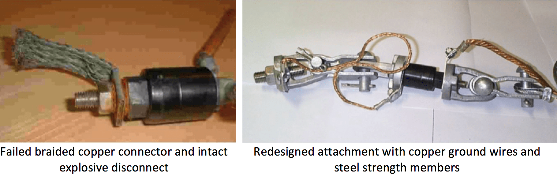
3. Explosive disconnects installed at the bottom of the arrester, thus allowing a long, energized lead to swing freely from the conductor;
4. Flexible leads that break part way between arrester and phase conductor, leaving a short stub that becomes a source of corona and electromagnetic interference;
5. Rigid leads that reduce electrical clearance and transfer cantilever forces to the arrester, which may not be rated for these loads;
6. Combinations of connection lead and strain relief chains that bypass the electrical isolation function of the explosive disconnect.
Vibration Damper Placement
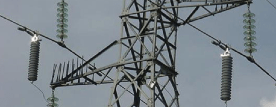
Many utilities have installed TLSA bodies or leads onto phase conductors, adding the new components somewhere between insulator clamps and vibration dampers. But few have followed Recommendation #1, i.e. to move the Stockbridge dampers at the same time as arresters are installed and thus preserve the original damping design. In cases where TLSAs have been placed close to dampers, as in Fig. 2, this advice to move the dampers into the spans, away from the TLSA, should be implemented immediately. It would be helpful to inspect some of the conductor beneath the TLSA to establish the extent of damage to inner conductor layers after a few years of service without proper damping.
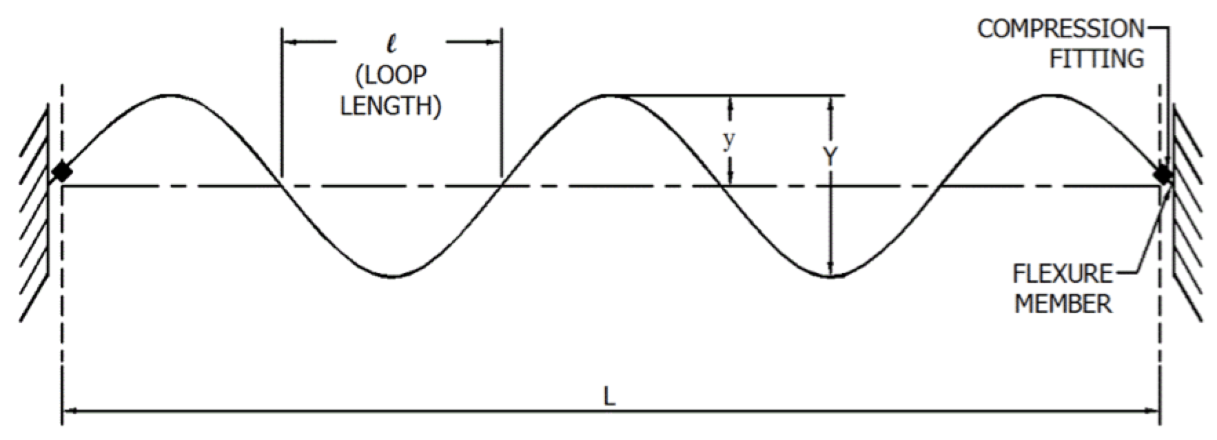
In cases where TLSAs have been placed about halfway between dampers and insulator clamps, the CIGRE analysis provides some breathing space for developing an action plan. Fig. 3 shows that vibration damper placement is a compromise, absorbing some energy at wind speeds of 1 and 7 m/s and a larger fraction of energy from winds having 3-5 m/s velocity.
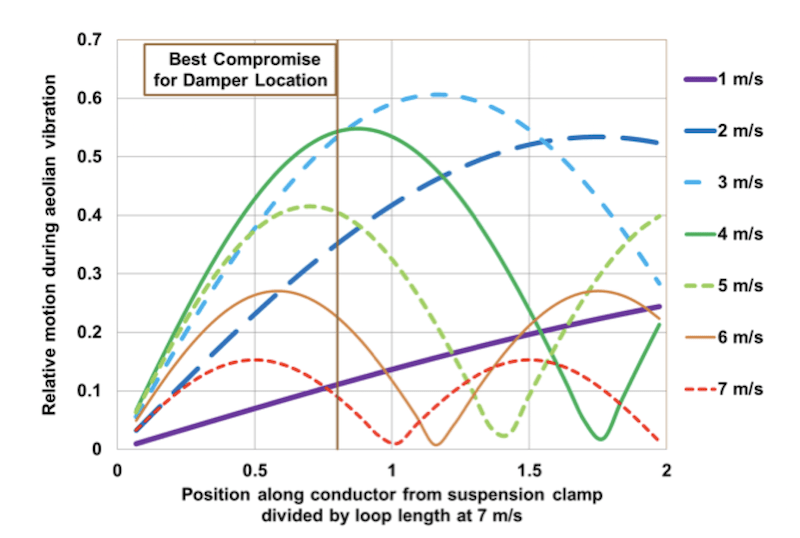
Mechanical engineers recommend a vibration damper placement at 80% of the loop length at 7 m/s as a good overall choice, considering the usual distribution of wind speed over a year. When a heavy TLSA is placed at 40% of the loop length, halfway between insulator clamp and an existing damper, Fig. 4 shows that there is reduction in damper effectiveness. However, the original design may have included some extra margin in damper power dissipation at vibration frequencies associated with certain wind speeds.
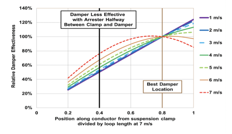
The placement of the TLSAs in Fig. 2 is approximately 20% of the original distance from damper to suspension clamp. Thus, the x-axis value in Fig. 4 is 0.2 and damper effectiveness has been reduced to 25-40% of the original value. This is too great a reduction to ignore. The dampers should be re-positioned. Since field tests have confirmed that TLSAs act as vibration nodes when suspended from phase conductors, the cumulative damage to the conductor under the arrester clamps should also be evaluated by periodic inspection. Electrical engineers have mastered concepts of resonance with RLC circuits and the recent IEEE introductory guide to Aeolian vibration can help guide their move into the mechanical domain.

Reliable Conductor Clamping Systems
CIGRE Technical Brochures provide historical consolidation of utility experience. TB 277, for example, describes the following design characteristics for clamping of spacer systems to phase conductors:
A spacer clamp should be capable of easy, reliable installation, preferably verifiable by ground based inspection and should provide a safe, reliable, non-damaging, long-term grip on the sub-conductor. High, localized clamping stresses should be avoided and the clamp conductor groove should be smooth and free from irregularities. The clamp should be smoothly profiled to minimize Corona and RIV discharges at specified voltages. Component parts should be secured and an energy storage mechanism is required to prevent loosening due to the effect of vibration, thermal cycling conductor and elastomer creep (in the case of elastomer lined clamps). All materials should be compatible with the conductor and avoid corrosion.
The clamps should:
• Maintain a suitable grip for the whole life of the line and in the whole range of service temperatures;
• Avoid conductor damage during installation and service;
• Be free of corona and RIV at maximum line voltage;
• Be installed without disassembling any parts;
• Be designed to minimize risk of improper installation;
• Be capable of being safely removed and re-installed on conductors;
• Allow installation survey from the ground;
• Ensure that individual components will not become loose during service.
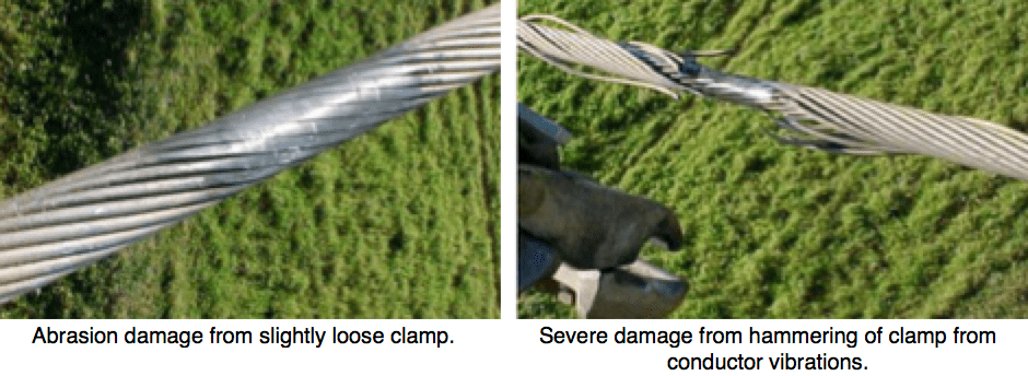
Substitution of ‘arrester’ for the highlighted ‘spacer’ is an appropriate goal for users and suppliers of NGLAs. Experience with rigid, articulated, spacer-damper and flexible spacers can guide selection of suitable TLSA hardware. Spacer clamps are generally made of primary aluminum alloy. Rubber-lined clamps used in many spacer-dampers may not be appropriate for NGLAs since a separate electrical connection would need to be made to allow the flow of lightning surge currents through the arrester’s MOV elements. However, a range of interesting articulation systems is in use for spacers and spacer dampers. Fig. 5 shows typical spacer clamping systems and components that could also be used in reliable NGLA installations. Safety plates with tabs that bend after tightening, or breakaway nuts that confirm correct installation torque are also mentioned as ways to avoid the conductor abrasion or hammering damage in Fig. 6.
Alternate Mounting Configurations
A range of mounting configurations for EGLAs and NGLAs has been described. For example, flexible leads, as shown in Fig. 7 fail rather quickly in service and can benefit from re-design that separates electrical and mechanical components. This leads to designs with higher parts count, weight and cost that should be validated with the same limit-cycle tests (10 cm, 106 cycles) as spacer systems.
There are several ways to address the limited durability of flexible leads, including:
• Specifications that require limit cycle testing, much like spacer dampers;
• Specifications that would apply an appropriate number of cycles and amplitude, considering the clamp mounting location and damper let-through frequency;
• Installation practices that place the disconnect-lead clamp near or on the insulator clamp;
• Use of stress relieving loops;
• Frequent and specific inspection.
Lead failures are easy to locate from helicopter or ground inspection, although it is difficult to establish whether the explosive disconnect has operated. It is possible that drone-based inspection will become cost effective and bring a closer focus on areas of interest near ring tongues and collars of flexible leads. As the leads break at the arrester or tower and fall, they may reduce electrical clearances. Electrically, the greatest benefit of partial TLSA application is often gained with installations on the bottom phases. Fig. 8 shows a mounting configuration with flexible lead that presents minimal danger to electrical clearance if it fails as designed and disconnects from the phase. However, if the lead breaks away from the top of the NGLA, nuisance flashovers can occur under side winds that blow the flexible high voltage connection towards the tower while it is still connected to the phase.


Recently, SaskPower in Canada completed construction of a shielded 230 kV line running parallel to an existing, unshielded 138 kV line for 300 km. Most of the access was by helicopter and this formed at least 10% of the total line cost of CA$ 330M. The lines run across a geographic feature known as the Canadian Shield, which is granite of high electrical resistivity. With no overhead ground wires, every lightning stroke to the I2P 138 kV line in Fig. 9 caused a flashover and short circuit across its polymeric insulators.

The I2P 138 kV transmission line was constructed with continuous counterpoise, although it had no shield wires to provide a suitable return path for fault current that would allow rapid operation of protective relays. Early in the project plan for the new I1K line, grounding investigations were carried out to establish whether continuous counterpoise would improve back flashover performance since the new design was fitted with an optical fiber groundwire (OPGW) for improved communication between terminals. A ‘Zed Method’ applied a voltage step between the base of existing I2P towers and a test lead, laid on the rock. The surge impedance of the test lead provided the transient connection to ground giving 400 mA pulse current. The tower base voltage rise was monitored in response to this impressed current. In a few cases, measured surge impedance of the tower base, with its counterpoise in place, was almost the same as the impedance of the insulated wire, draped on the ground. More typically, the guyed structure had an impedance of 140 in isolation that fell to a constant 77 when the counterpoise was reconnected. The tests concluded that continuous counterpoise, draped across the Canadian Shield rock surface, did not provide much of a grounding path. Each leg of counterpoise had a surge impedance of about 360 , meaning that more than 10 radial wires would be needed to achieve a footing impedance of 35 . At that stage, many options were considered and refined down to two choices for the new I1K line:
1. Moving the counterpoise up and suspending it from the tower, in an under-built location below the phases, where it could be inspected by helicopter; or
2. Installing surge arresters across all three phases

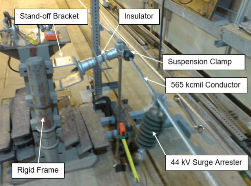
The selected arresters in Fig. 11 met the IEC 60099-4 Edition 2.2 Line Discharge Class 3, with 58 mm MOV block diameter. In Edition 3 of this standard, the new classification is SM with Q¬rs¬ of 2.0 Coulomb, corresponding to Energy Class E of IEEE C62.11/2012. The arresters weigh about 60 kg each with additional mass from the corona ring. With the choice of arresters over grounding made early in the project plan, it was possible to advise the manufacturer of the vibration dampers that their design, the twin pairs of dumbbell weights at the left of Fig. 11 would also need to protect the conductor under the arrester clamp. Close inspection shows that armor rod has been placed between conductor and NGLA saddle clamp, further improving mechanical durability and hopefully leading to long service life.

Another consideration in application of polymeric-housed TLSAs is shown in Fig. 12 and in a region prone to forest fire. One test along the I2K line near Island Falls showed that the ground temperature after a recent forest fire was hot enough to melt the connection from tower to counterpoise. In this case, the counterpoise was found to be otherwise intact, since it provided a continuous reduction in footing impedance when re-connected to the tower. This kind of damage is difficult to inspect from helicopter and forms an additional argument for selecting TLSAs (or underbuilt ground wires) as an alternative to grounding with continuous counterpoise.

Improvements in Arrester Mechanical Standards
There are many standards that describe mechanical vibration test methods for transmission line components. Some important definitions are found in Figs. 13, 14 & 15.
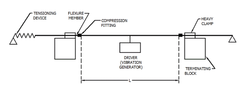
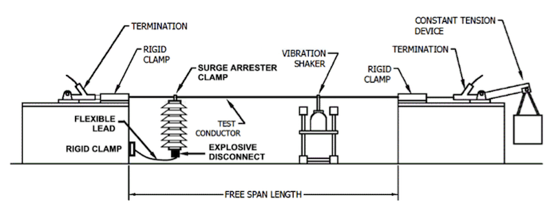
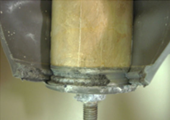
Bundle spacer systems are tested with mechanical oscillations that simulate in-service conditions. For example, a galloping test applies a 1 Hz oscillation frequency with 10-20 cm amplitude for 106 cycles. Components pass the test if there are no visible changes. This would seem to be a reasonable requirement for complete arrester/flexible lead systems. However, galloping tests are severe. An adaptation of the vibration test in Fig. 15 was set up in Fig. 16 to simulate galloping effects on a 44 kV NGLA located about 710 mm from a suspension clamp. Galloping amplitude of about 0.8 m was achieved on a 20 m span. The purpose was to simulate damage found in the field and Fig. 17 shows that this was achieved.
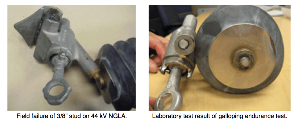
The damage in Fig. 17 was partially mitigated if the clamp was tight and flush to the top of the arrester. The stud fatigue damage shown in Fig. 18 occurred after 20k to 66k cycles. This is consistent with findings about galloping endurance of Stockbridge dampers on galloping test lines.
Conclusions
Transmission line surge arresters are large enough and heavy enough to affect the performance of vibration dampers. Field tests have confirmed that TLSAs act as vibration nodes when suspended from phase conductors. New CIGRE guidance recommends that existing vibration dampers should be displaced along the conductor, treating any conductor-mounted arrester as a new clamp and node to be protected. Damper re-positioning should be an inspection and remediation priority for installations where arresters have been placed close to pre-existing dampers. Concerns with long-term durability of the conductor should include re-selection of appropriate dampers for the new span as well as improved arrester attachment using armor rods or other stress reduction clamps. Guidance, including standards for limit-cycle testing, should be obtained from clamping systems that have proven suitable for bundle spacers.
TLSA accessories, including flexible lead clamps, corona rings for NGLAs and arc receivers for EGLAs, should meet appropriate vibration and flexion criteria for an anticipated 20 to 50 year service life. Placement of light accessories close to existing insulator clamps is recommended to reduce level of vibration. Since some accessories are about the same weight as vibration dampers, placement near existing dampers should be reviewed with manufacturers and supported by bending amplitude verification testing.