Metal oxide varistors play a vital role in protecting electrical systems from voltage surges triggered by lightning and switching operations.
This edited contribution to INMR by Dr. Aderibigbe Adekitan at Tridelta Meidensha in Germany examines the issue of uneven voltage distribution across metal-oxide varistor blocks, as commonly associated with tall arresters, and which can lead to thermal stress on the metal-oxide varistor blocks in the upper section of the surge arrester.
In his investigation, finite element analysis was applied to evaluate the voltage distribution across two- and three-unit 435 kV rated surge arresters. Application of a grading ring reduced the U/Uc ratio from 1.22 to 1.18 for the two-unit arrester, indicating an improved voltage distribution. Results reveal that proper arrangement of multi-unit arresters and uniform distribution of the metal-oxide blocks within the arrester can lead to a more uniform voltage distribution. These findings also emphasize the importance of ensuring adequate design considerations in development and manufacture of surge arresters.


Electrical power systems must be adequately protected to ensure consistent reliability and service longevity. Lightning strikes, switching operations, which are an integral part of power station processes, and other related disturbances can trigger overvoltage transients in electrical systems. Surge arresters are installed to protect equipment from the negative impact of these undesired but sometimes unavoidable system overvoltages and are crucial for maintaining the integrity of electrical systems.
Surge arresters protect insulators, such as bushings, in power systems by clamping surges that can exceed the basic insulation level (BIL) of the protected device, thereby reducing insulation stress and preventing flashover. By implication, risk of thermal or mechanical damage is minimised, thereby enhancing the overall reliability of the power system component. The advent of ZnO blocks led to the development of the first non-gapped metal-oxide surge arrester (NGMOSA) in 1976. Over the years, this concept gained popularity and acceptance across various utilities and industries worldwide. ZnO arresters can handle high non-linear energy and are more reliable than silicon carbide (SiC).
Surge arresters are designed to comply with relevant standards for optimal performance. Design, construction and testing of the NGMOSA are regulated by standards such as IEEE Std C62.11-2020 and IEC 60099-4. The parameters of a surge arrester determine the suitable system voltage and areas of application of the arrester.
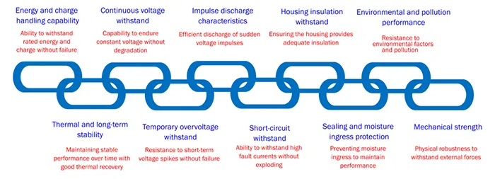
As illustrated in Fig. 1, a surge arrester designed in compliance with current industry practices must demonstrate certain capabilities in terms of continuous voltage withstand, energy and charge withstand rating, short-circuit rating, ageing and environmental durability, mechanical strength, etc. Each of these performance evaluation criteria is like a continuous link in a chain that must not be broken for prolonged service reliability. Compliance with these requirements is established during type testing of an arrester design series and routine testing of a newly produced arrester.
Metal oxide varistor blocks (MOVBs) are the primary components in surge arresters. An MOVB is a semiconductor device primarily composed of zinc oxide (ZnO) grains embedded in a polycrystalline matrix. Due to its nonlinear voltage-current characteristics, it is highly effective for surge protection. A stack of MOVBs achieves the protective function of a surge arrester.
Number of blocks ultimately determines the total block height, defines the continuous operating voltage of the arrester, residual voltage under impulse currents and its temporary overvoltage (TOV) withstand rating. Width or diameter of the block defines its current handling capacity, and ultimately, these parameters determine the energy absorption rating of the blocks. In some cases, achieving a desired residual voltage or energy rating may require installation of MOVBs in parallel if a suitable single, larger-diameter block is unavailable or impractical.
To achieve higher voltages, multiple surge arrester units are coupled together vertically, and MOVBs at the top of the uppermost unit are often subjected to more voltage stress than the rest of the blocks in the arrester column due to stray capacitances to the earth acting on the arrester column, resulting in a non-uniform voltage distribution and faster ageing. A conductive ring, referred to as a grading ring, which is placed near the high-voltage end of surge arresters, becomes necessary in such cases to improve the voltage distribution across the blocks and to prevent excessive voltage stress on MOVBs stacked at the top of the column, which could lead to thermal runaway and arrester failure.

Height of the MOVBs determines rated voltage of a surge arrester. MOVBs have a fixed ratio between their rated and residual voltage, and this often requires a trade-off to achieve the desired protection level. A surge arrester with a specific rated voltage consists of a certain number of blocks based on the established manufacturer’s dimensioning factors. It is important to evaluate the effects of the position and arrangement of MOVBs on the stress distribution within the arrester.
Stress distribution can vary significantly for the same number of blocks if placed at different physical positions in the stack. Different tools, such as finite element method (FEM), Maxwell, COMSOL Multiphysics, boundary element method, EMTP-ATP, have all been used in various studies on surge arresters. FEM has been applied to study the voltage distribution across a surge arrester and for other purposes, including the investigation of the electrothermal attributes of surge arresters.
FEM simulations require significant computational resources, particularly for 3D models with fine meshes. Models with finer mesh elements improve accuracy, but increase simulation time and memory requirements, as observed in studies on grading ring optimization.
A comparative surge arrester simulation study in IEC 60099-4 using both 2D and 3D computations established the sufficiency and accuracy of the 2D model with a significant simulation time advantage. This study assessed the practicality of incorporating a ‘virtual’ grading ring in axisymmetric simulations to replicate the effect of grading ring supports, and the application of other model simplifications proposed by IEC 60099-4. FEM is a vital tool for modelling and optimizing surge arrester designs and provides detailed insight into voltage distribution, material performance, and impact of environmental factors.
Ongoing research is being conducted to further improve the design, performance, and reliability of ZnO-based arresters. A key area is the application of high-gradient ZnO materials in gas-insulated surge arresters for gas-insulated switchgear (GIS) applications. High-gradient MOVBs have higher electric field stress withstand and can therefore operate at higher voltage gradients and higher voltage ratings per block. The associated high electric field is not a challenge because of the insulation withstand of the sulphur hexafluoride (SF6) gas in GIS arresters. This innovation extensively minimizes height of GIS surge arresters, improving performance against fast transients and enhancing voltage distribution.
Research studies are being conducted to develop new high-gradient ZnO materials doped with rare earth oxides. These materials also reduce grain size of ZnO varistors, leading to higher voltage gradients and compact arrester designs. Air-insulated surge (AIS) arresters only have low-dielectric air as insulation and can only use standard gradient MOVBs. Optimal arrester design and ZnO block arrangement within the arrester, coupled with height reduction where necessary, are required to ensure good voltage distribution for AIS arresters.
Recent studies have further evaluated the ability of arrester materials to handle very fast transients, such as those caused by high-altitude electromagnetic pulses (HEMP). Continuous research in this field will help shape the design of future surge arresters.
This study presented below investigated voltage distribution across a 435 kV-rated polymer tube design surge arrester and highlights the impact of different MOVB arrangements as well as improved voltage distribution from using grading rings.

Methodology
This study applies a FEM-based approach using FEMM 4.2 to simulate a 435 kV-rated, polymer-tube-design surge arrester with a continuous operating voltage (Uc) of 348 kV rms or 492.15 kV peak. The maximum system voltage is 550 kV. The capacitive arrester model simulation was performed using FEM, while the capacitive model with nonlinear resistive elements, which provides more realistic results, was implemented using ATP EMTP, and the final data review and analysis were performed in MATLAB.
Modelling and analysis of the arrester, including the MOVBs and metal spacers, is based on guidelines and the resistance-capacitance arrester model circuit provided in Annex F of IEC 60099-4:2014.
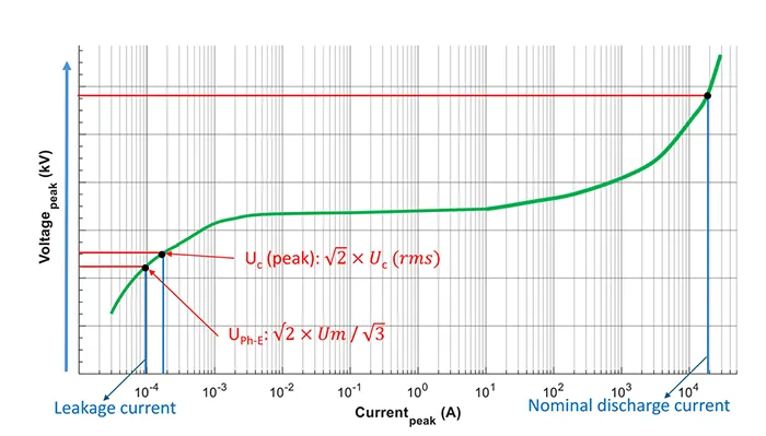
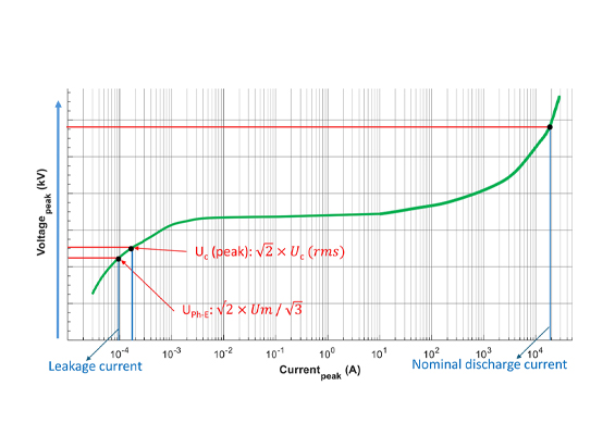
A surge arrester installed between the phase and the earth operates normally at the nominal phase-to-earth voltage level. The surge arrester can also safely continuously operate at the Uc as illustrated in the sample VI curve in Fig. 2. This study evaluates the variation in the field distribution across the arrester at these two voltage levels. For a particular arrester design series, the number of MOVBs to achieve a specific voltage is established based on the type test results.
Two versions of the arrester are considered in this study: a two-unit arrester with a total height of 4240 mm, where each unit has the same height and number of blocks; and a three-unit version with a total height of 4560 mm, consisting of two identical units with 15 blocks each and a third, longer unit with 34 blocks. Effect of altering position of each unit in the three-unit arrester is investigated.
This study investigates the effect of distributing the same number of ZnO blocks differently in the arrester. It considers MOVBs concentration; uniformly, at the top, at the bottom, at the upper and lower ends (top and bottom) and at the centre as illustrated in the simplified drawing in Fig. 3, from (a) to (e). IEC recommends including the line conductor in the model. This study examines the effect and the level of improvement achieved by incorporating a grading ring with a diameter of 1500 mm in the arrester. The arrester has 64 ZnO blocks stacked vertically in the housing, and the relative permittivity of the MOV block is 800. The pedestal is 2000 mm high and 150 mm wide.
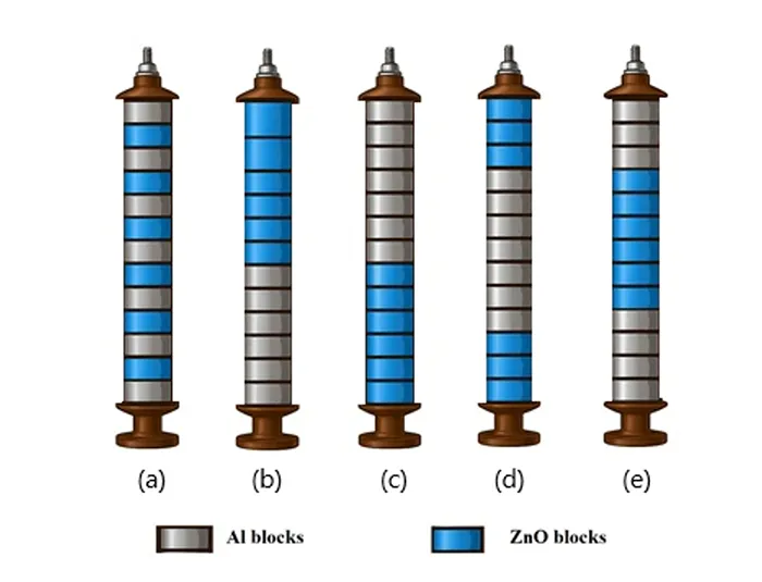
(a) Uniform (b) Top (c) Bottom (d) At the top and bottom (e) Centre.

Results
A. Effect of Grading Ring
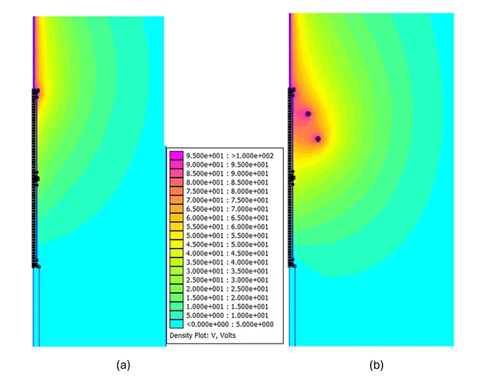
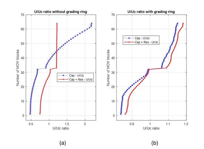
The first FEM simulation highlights the beneficial effect of a grading ring on a surge arrester operating at the continuous operating voltage. The 435 kV rated arrester with 2 similar units is analysed first without a grading ring and then with a 1500 mm diameter grading ring. The normalized potential distribution across the surge arrester with and without a grading ring is shown in Figs. 4(a) and 4(b). The ratio of the voltage (U) across each block from the FEM simulation divided by the average Uc per block for both cases is plotted in Figs. 5(a) and 5(b).
Without applying a grading ring, maximum U/Uc ratio is 2.18 for the capacitive model and 1.22 for the capacitive-resistive model. With grading ring, values were reduced to 1.15 for the capacitive model and 1.18 for the capacitive-resistive model. These values and the voltage equivalent can be compared with the unbalance factor established during the long-term stability test under continuous operating voltage. This helps confirm if any of the blocks are over-stressed beyond a reasonable limit.
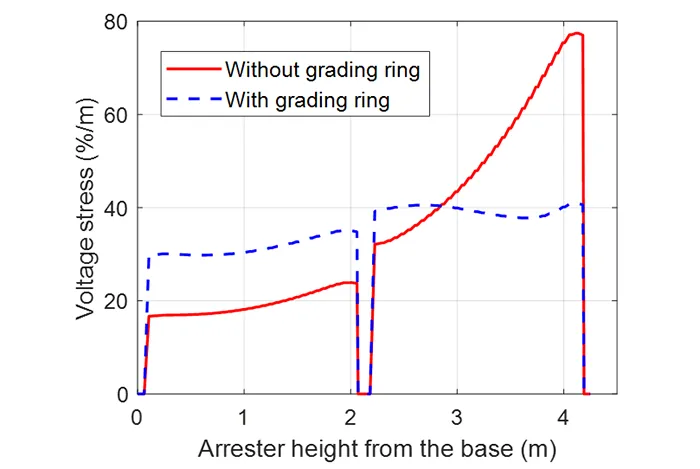
Voltage stress across the MOVBs from the base upward is plotted in Fig. 6. The analysis without a grading ring resulted in a maximum stress of 77.4% per meter with quite a non-uniform voltage stress distribution with peaks around the upper blocks in the second arrester units. Application of a grading ring improved the voltage stress pattern and reduced the maximum value to 40.9% per m.
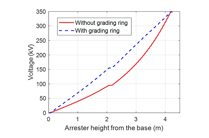
A similar pattern is observed in Fig. 7, with the bulk of the voltage distributed along the MOVBs in the upper unit for the case without a grading ring. These results show the significance of the stray capacitance on the voltage distribution along the arrester without a grading ring and the beneficial improvements obtained by the introduction of the grading ring. This study does not include further grading ring optimization analysis.

The initial simulation applied a Uc of 492.15 kV peak. In this section, the peak phase-to-earth voltage of 449.1 kV is applied for a comparative review as illustrated in Fig. 2. This represents the peak nominal phase-to-earth system voltage (Uph) that the arrester should be subjected to.
The result for this case is presented in Fig. 8(a) for the capacitive model and Fig. 8(b) for the capacitive-resistive model. There is no difference in the U/Uc distribution for the capacitive model when Uph and Uc were applied, both with and without a grading ring. The result from the capacitive-resistive model is quite different, with a unique data trend for each of these cases.
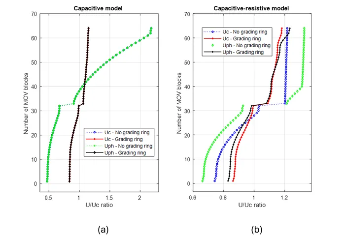
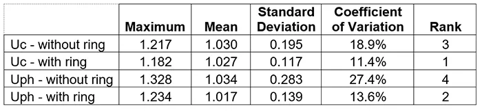
Coefficient of variation, as shown in Table 1, reveals interesting trends in dispersion. U/Uc distribution from the application of Uc and a grading ring has data points closest to its mean value, while the U/Uc distribution from the application of Uph without a grading ring has data points farthest from its mean value. For this surge arrester under study, the result shows that a lower system voltage, such as Uph, does not necessarily imply a better U/Uc distribution than a higher system voltage, such as Uc. However, actual voltage U per block can be higher for each of the MOVBs for the higher system voltage.
B. Effect of MOVB Arrangement Within Housing
This section examines the effect of concentrating the MOVBs in different sections of the arrester housing. Five different block arrangements are analysed: uniform block distribution, concentration at the top, concentration at the bottom, concentration at both the top and bottom, and concentration at the centre, as illustrated in Fig. 3. A grading ring is included in the simulation, and the applied voltage is Uc.
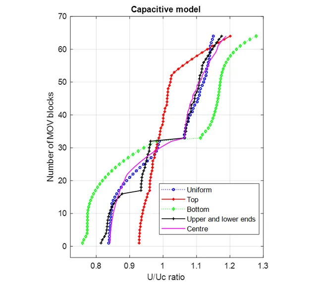
Peak Uc is applied for the 5 MOVB configurations. U/Uc distribution for the capacitive model and the resistive-capacitive model is presented in Figs. 9 and 10, respectively. Coefficient of variation, which is a measure of dispersion, is presented in Table 2 for the capacitive model. It shows that the concentration of blocks at the top ranks first, the uniform distribution ranks third, and the concentration of blocks at the bottom ranks fifth and last in the dispersion analysis.
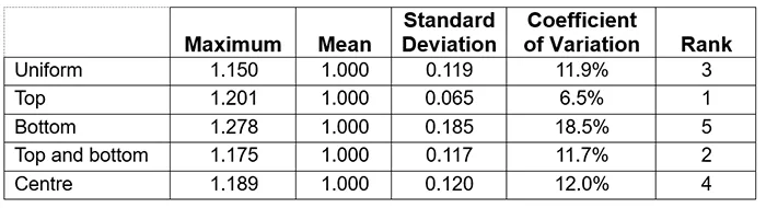
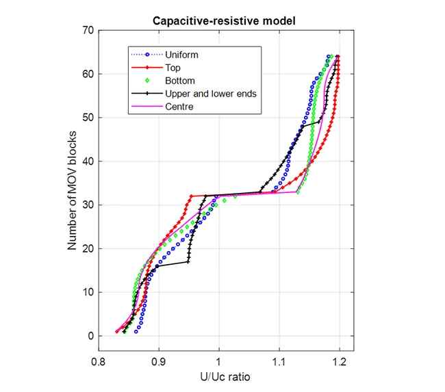

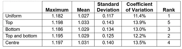
Table 3 presents the results for the capacitive-resistive model, which represents the more realistic solution. It shows that the uniform distribution of blocks ranks first, while the concentration of blocks at the top, which previously ranked first in the capacitive analysis, now ranks fifth and last in the dispersion analysis. The concentration of blocks at the extreme ends (i.e. at both the top and bottom) ranks second both in the capacitive and capacitive-resistive models.
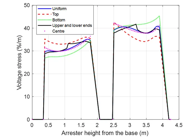
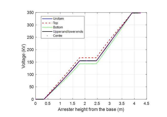
The uniform distribution of blocks has the lowest maximum U/Uc ratio of 1.15 and 1.18, respectively, for both models. Voltage stress across the MOVBs from the base upward is plotted in Fig. 11. Peak voltage stress is 40.9% for the uniform configuration, 42.7% for the top, 45.4% for the bottom, 41.7% for the top and bottom and 42.2% for the centre configuration. The uniform MOV block arrangement has the best voltage stress distribution. Fig. 12 shows the voltage distribution for the 5 MOVB configurations.
C. Effect of Interchanging Arrester Units
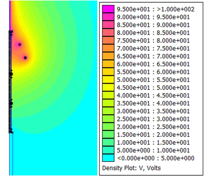
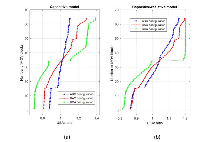
This section presents results from the simulation of a three-unit version of the 435 kV rated arrester with a height of 4560 mm. The voltage applied is Uc. The longer unit is referred to as A, while the second and third units, B and C, are identical in height and contain the same number of MOVBs. The normalised potential distribution across the 3-unit surge arrester in the ABC configuration is shown in Fig. 13. The ratio of the voltage (U) across each block from the FEM simulation divided by the average Uc per block is plotted in Fig. 14(a) for the capacitive model and 14(b) for the capacitive-resistive model for the three configurations ABC, BAC and BCA considered.
The simulation reveals a consistent order of results for both the capacitive model and the capacitive-resistive model. The ABC configuration with the tallest unit at the top has a maximum U/Uc ratio of 1.10, while the BAC configuration with the tallest unit at the centre has a maximum U/Uc ratio of 1.29, and BCA configuration with the tallest unit at the bottom has a maximum U/Uc ratio of 1.39, representing the worst voltage distribution among the three cases. A similar result pattern is observed for the capacitive-resistive model with U/Uc ratios of 1.16, 1.19 and 1.20, respectively. This indicates that placing the unit with the highest number of blocks at the top resulted in the best voltage distribution for this case study.
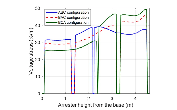
Voltage stress along the surge arrester is shown in Fig. 15 for the three configurations. The peak voltage stress is 39.1% per meter for the ABC arrangement, which exhibits a more uniform voltage stress distribution compared to the other two configurations. For the BAC configuration, the peak voltage stress is 45.8% per m, while for the BCA configuration, it is 49.2% per m.
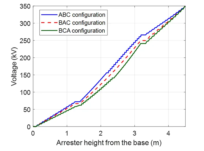
Voltage distribution based on the position of the arrester units is plotted in Fig. 16. The voltage distribution for the ABC configuration has a steeper voltage distribution across the lower blocks, implying a better voltage distribution across the blocks than the BAC and BCA configurations.
The key findings include:
a. The voltage distribution across tall surge arresters can be significantly improved by using grading rings. The grading ring reduces the voltage stress across the ZnO blocks in the upper region of the surge arrester;
b. A measure of dispersion using the coefficient of variation for the capacitive-resistive model revealed that a lower system voltage, such as Uph, may not necessarily imply a better U/Uc distribution than a higher system voltage, for example, Uc. However, the actual voltage U per block may be higher for each ZnO block for a higher system voltage;
c. A uniform distribution of blocks within the arrester housing helps achieve an optimal U/Uc distribution;
d. For multi-unit arresters, the longest unit with the highest number of ZnO blocks should be positioned at the top of the arrester to achieve the best voltage distribution.
Conclusions
Surge arresters are vital for protecting electrical equipment and insulators from switching and lightning impulses in electrical systems. Tall arresters can experience uneven voltage distribution due to stray capacitances to earth.
This FEM study confirmed that application of a grading ring helps in redistributing electric field more uniformly across the arrester and minimizing voltage stress at the top end of the arrester. Applying a grading ring to a 2-unit arrester reduced maximum U/Uc ratio from 1.22 to 1.18 for the capacitive-resistive model.
The study also evaluated and confirmed the impact of 5 different MOVB arrangements within the arrester units. During production, it is important to ensure that MOVBs are uniformly distributed across the length of the arrester to achieve optimal voltage and electric field distribution.
References
1. Huang, S.-J. and C.-H. Hsieh, A method to enhance the predictive maintenance of ZnO arresters in energy systems. International Journal of Electrical Power & Energy Systems, 2014. 62: p. 183-188.
2. Raju, K., et al., Development of high gradient ZnO arrester material for high voltage applications. IEEE Access, 2020. 8: p. 115685-115693.
3. Latiff, N.A.A., et al., Measurement and Modelling of Leakage Current Behaviour in ZnO Surge Arresters under Various Applied Voltage Amplitudes and Pollution Conditions. Energies, 2018. 11(4): p. 875.
4. IEEE C62.11: IEEE standard for metal-oxide surge arresters for AC power circuits (>1 kV). 2020.
5. IEC 60099-4: Surge arresters – Part 4: Metal-oxide surge arresters without gaps for a.c. systems. 2014, Ed. 3.0.
6. Meshkatoddini, M.R., Metal oxide ZnO-based varistor ceramics, in Advances in ceramics – electric and magnetic ceramics, bioceramics, ceramics and environment, C. Sikalidis, Editor. 2011, IntechOpen: Rijeka.
7. Prasad, V., A Review of Voltage Distribution on Metal Oxide Surge Arrester and Suggestions for Improvement in High Voltage Applications. IEEE Latin America Transactions, 2025. 23(6): p. 479-486.
8. Alti, N., A. Bayadi, and K. Belhouchet, Grading ring parameters optimisation for 220 kV metal-oxide arrester using 3D-FEM method and bat algorithm. IET Science, Measurement & Technology, 2021. 15(1): p. 14-24.
9. Jinliang, H., et al., Potential distribution analysis of suspended-type metal-oxide surge arresters. IEEE Transactions on Power Delivery, 2003. 18(4): p. 1214-1220.
10. Meng, P., et al., Breakdown phenomenon of ZnO varistors caused by non-uniform distribution of internal pores. Journal of the European Ceramic Society, 2019. 39(15): p. 4824-4830.
11. Nurul, A.A.L., et al., Parametric Evaluation of 11kV Zinc Oxide Surge Arrester using Finite Element Analysis Model. IOP Conference Series: Materials Science and Engineering, 2021. 1127(1): p. 012038.
12. Waghmare, V.V., V.K. Yadav, and I.M. Desai. Optimization of Grading Ring of Surge arrester by using FEM method, PSO & BAT Algorithm. in 2022 2nd International Conference on Advance Computing and Innovative Technologies in Engineering (ICACITE). 2022.
13. Zhang, C., et al. Electric field analysis of high voltage apparatus using finite element method. in 2010 Annual Report Conference on Electrical Insulation and Dielectic Phenomena. 2010.
14. Tighilt, F., A. Bayadi, and A.M. Haddad. Voltage distribution on ZnO polymeric arrester under pollution conditions. in 45th International Universities Power Engineering Conference UPEC2010. 2010.
15. Seyyedbarzegar, S.M. and M. Mirzaie, Application of finite element method for electro-thermal modeling of metal oxide surge arrester. Computer Applications in Engineering Education, 2015. 23(6): p. 910-920.
16. Kannadasan, R., P. Valsalal, and R. Jayavel, Performance improvement of metal–oxide arrester for VFTs. IET Science, Measurement & Technology, 2017. 11(4): p. 438-444.
17. Bowman, T.C., T. Kmieciak, and L.B. Biedermann, Nanosecond Transient Validation of Surge Arrester Models to Predict Electromagnetic Pulse Response. IEEE Transactions on Electromagnetic Compatibility, 2025. 67(1): p. 286-294.