For over 30 years, INMR has travelled the globe covering power line and substation projects on all continents. It has also been invited into factories for electrical equipment as well as into test laboratories worldwide. During these many site visits, thousands of photos were used to support the resulting technical articles.
In this first of a 3-part series, the photos themselves are the primary focus. Favorite photos were selected based on their meeting one or all of the following criteria:
1. Unique in the sense that they capture a special situation that cannot easily be replicated;
2. Provide unusually high technical or visual overview into the topic of interest; and/or
3. Offer special insight into some aspect of power transmission and distribution.
Biological Contamination on Insulators
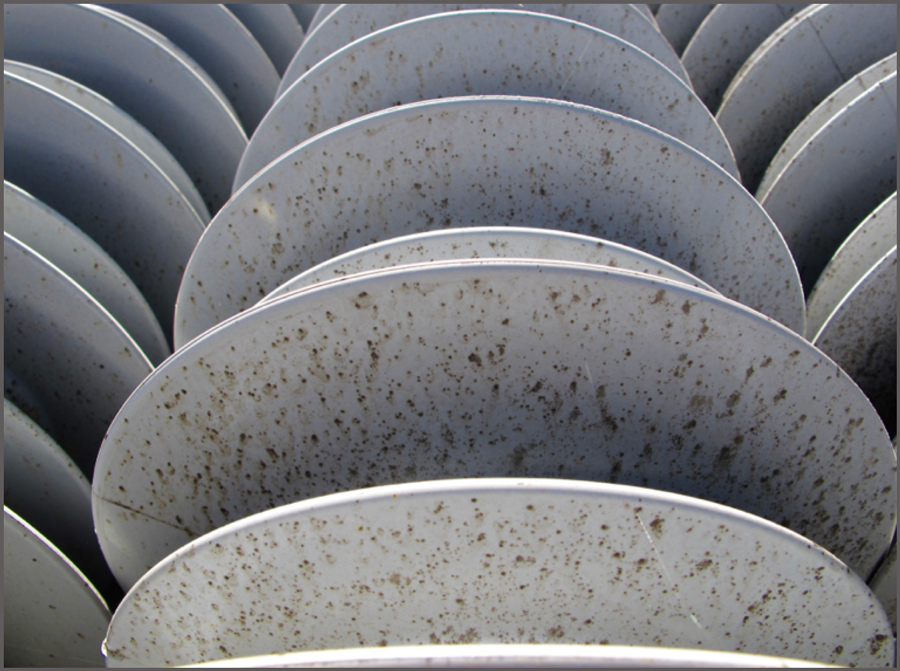
The Back Story
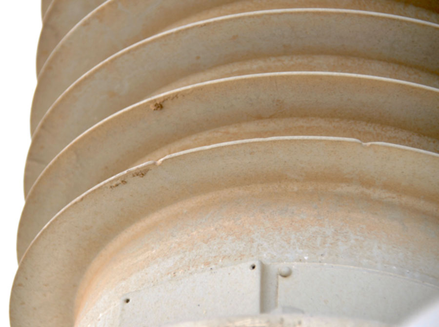
In a service environment characterized by elevated humidity and temperature as well as presence of species of mould, surfaces of insulators – both ceramic and composite – can become colonized. The effect on inert glass or porcelain surfaces is minor since these materials are already hydrophilic. Mould growth can therefore only increase thickness of the pollution layer. In the case of composite insulators with hydrophobic surfaces, however, this valued performance-enhancing property can be temporarily diminished or even lost. Fortunately, field experience has shown that in only few cases does mould growth require removal. The decision whether or not to remove is then usually taken only as preventative measure once heavy colonization has been identified. Positive experience in this regard is confirmed by laboratory investigations that show only white rot fungus can degrade the main components of the silicone rubber polymer.
It has now been reported that mould growth can also occur during storage of composite insulators in crates exposed to rain and warm temperature. These crates are typically wood and import into many countries requires pre-treatment but research has demonstrated that this has no influence on the potential for subsequent mould growth. Rather, practical experience suggests that design of crates calls for a compromise: on the one hand, holes or slots are needed to ventilate the internal space; on the other, their size must be small enough to prevent ingress of pollution or entry by creatures such as rodents.
Depending on climate, wood crates can quickly deteriorate when left exposed to the environment. If insulators inside crates are unprotected or if the protection was removed from earlier use, water with organic content from the wood can come into contact with the insulator surface and lead to colonization by fungus. A wide variety of species are available worldwide to create such ‘biogenic’ pollution. From the user perspective, there are two possible scenarios:
1. Insulators can be covered by fungal species such as Aspergillus niger and Cladiosporium which are superficial and can easily be removed, with the previously colonized areas again becoming fully hydrophobic, or;
2. Combined colonization by mould species Chaetomium and Cladosporium, which have a symbiotic interaction with Methylobacteria, can create a pinkish appearance on insulator surfaces. While the mould is easily removed, the colour diffuses into the silicone rubber bulk material. Surfaces with such pinkish residue return to being hydrophobic after cleaning and therefore regain their original performance. But there may be some loss in aesthetic appearance.

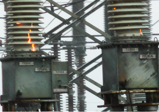
Reducing Leakage Current on Polluted Insulators
The Back Story
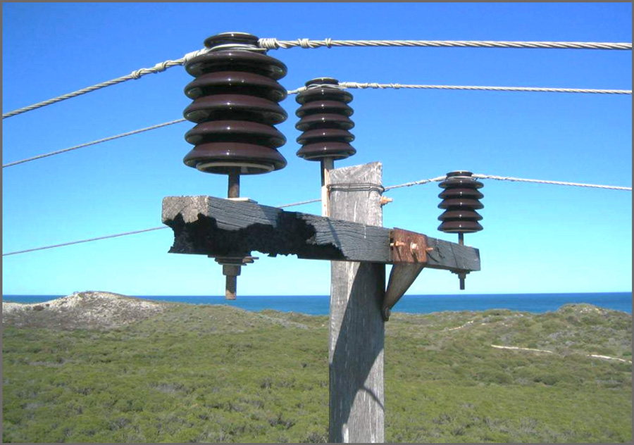
In 2005, Australian utility, Western Power, determined that while the proportion of its distribution structures affected each year by pole top fire was less than 0.1 per cent, with some 800,000 poles in the system this still meant several thousand fires to cope with annually. Poles catch fire for a number of reasons such as the result of sparks between the base of an insulator and either cross-arm or pole. Similarly, dry band discharges along the cross-arm or pole can also trigger a fire. Sparks or discharges are typically caused by leakage current along the surface of a polluted insulator when it is wetted by fog, mist or light rain. If the insulator is tightly fastened to the cross-arm or employs a spring washer, such sparking does not generally occur. However, the expansion and contraction of wood due to changing weather conditions makes it necessary to periodically manually tighten the insulator pin – a costly and time-consuming process.
Various mitigation methods had been used in Australia to deal with pole fires. In one, the base of the distribution insulator is bonded to the earth wire, thereby eliminating sparks and dry band discharges. However, in case of insulator flashover, it is likely that the earth wire will melt and possibly cause the pole to catch fire. A variant to this approach is to bond all three insulators to a plate that is kept at a distance from another plate connected to the earth wire.
Since the real source of the problem is the leakage current flowing along the insulator surface, it is logical to try to eliminate or at least substantially reduce these currents. Two methods used in this regard are to wash the pollution from the insulator surface; the other is to coat the insulator with a product that prevents leakage currents. Washing is laborious and costly and the main problem becomes how best to decide when it should be done. Western Power therefore began utilizing products to prevent leakage current, namely silicone grease and RTV silicone coatings. For example, starting in 2003, a four-year program saw 10,000 poles greased annually.
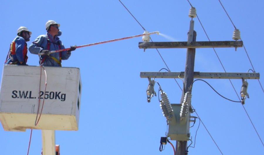
Spraying grease was done live to bonded as well as un-bonded poles and one application was expected to be effective for about four years. But after this service life, renewing the grease involved the cumbersome task of removing the existing layer entirely using high-pressure washing which carried concerns about the impact of contaminated grease on both insulators and the environment. Western Power then began relying more on RTV silicone coatings to prevent formation of leakage currents on the surfaces of insulators. The first trial application involved a 132 kV line running around the city of Perth, where insulators had to be washed up to four times during the critical dry season. Based on positive experience, live application of RTV silicone coatings later began on distribution insulators in areas exposed to pollution to prevent problems arising from excessive leakage currents.
Overcoming Widespread Pollution Flashover Events
The Back Story
Beginning in the 1970s, the Chinese power system experienced a growing number of massive outages triggered by pollution flashover. Between the mid 1980s and 2006, there were 44 large-scale outages linked to progressively worsening air quality across the country. For example, there were extensive pollution flashover outages in East China at the beginning and end of 1989, in North China at the start of 1990 and in East and Central China at the end of 1996. All caused great economic losses and served as a powerful lesson of what can go wrong. Later, repeated large-scale, inter-provincial pollution flashover accidents occurred across Eastern and Central China. It was from that point that a key lesson was learned: preventing pollution flashover by requiring frequent manual cleaning of insulators was insufficient and no longer belonged in the country’s standards. In addition, there was also recognition that levels of air pollution could not be reduced over a short time and, if anything, would only worsen. At the same time, given the country’s rapid pace of industrialization, it was clear that these types of incidents would have to be substantially reduced given short-term plans to greatly increase the number of overhead lines, construct new DC lines and continually upgrade transmission voltage levels.
Assuring a safe and reliable power supply meant eliminating these flashovers and this became an urgent priority for the power sector. The best way to achieve this was by researching and properly classifying pollution levels in different service areas to assure that insulation is always dimensioned for the types of environmental stresses it will experience. But achieving this required establishing the actual pollution situation affecting each service area as well as how these pollution levels were changing over time. This would be the only way to suitably dimension outdoor insulation.
Based on this, China EPRI, Tsinghua University and local institutes began a process of research that lasted more than 10 years. This work was supported by the State Grid Corporation of China and allowed the SGCC to issue its standard Q/GDW 152 “Pollution classification and external insulation selection for electric power system” in 2006. The basic principle put forward in this document was that dimensioning insulators was to be independent of any requirement to clean them and that there would also have to be an additional safety margin. A pollution classification methodology based on the relationship between SPS and ESDD/NSDD was also provided.
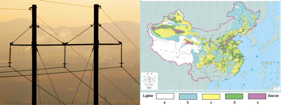
A new pollution classification method was put forward and a pollution distribution map created. Much effort went into establishing the equivalence of pollution properties and corresponding flashover testing. After the pollution distribution map was created, insulators were suitably dimensioned based on data from pollution withstand voltage tests. Moreover, high quality silicone rubber composite insulators and improved RTV coatings began to be developed and applied widely across China’s power system. With all these key elements achieved, past large-scale pollution flashover outages were effectively avoided and trip-out rate from pollution flashover in China was sharply reduced.

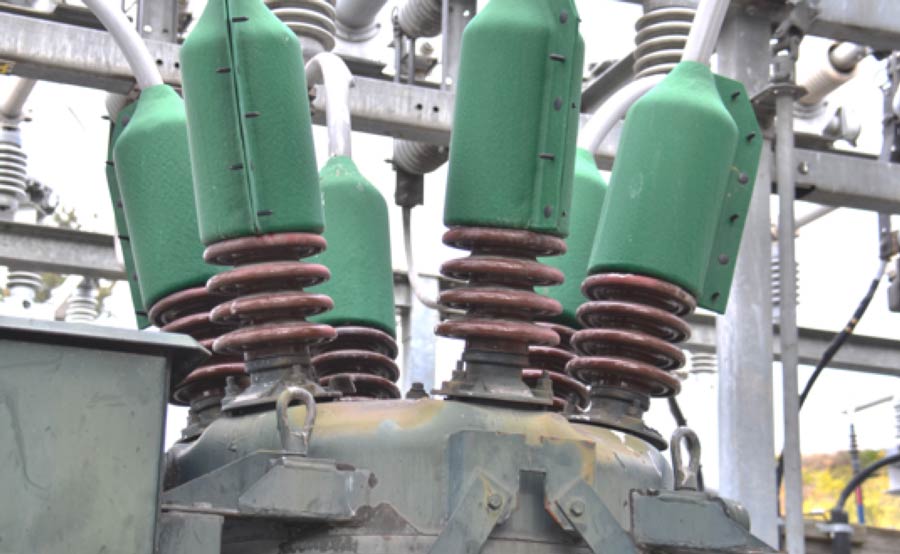
Technological Development of Distribution Arresters
The Back Story
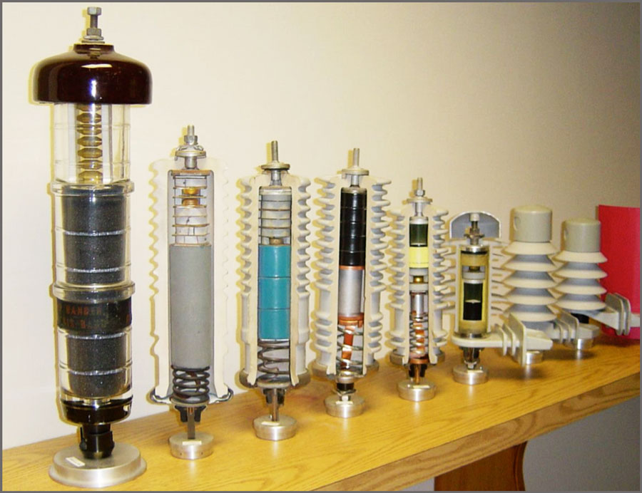
There have been two fundamental shifts in technology for distribution surge arresters: one has seen substitution of metal oxide varistors in place of the silicon carbide gap-type designs dating from the 1950s; the second has consisted of near total replacement of porcelain by polymeric materials as the external housing. Together, these changes completely transformed the scale, appearance and performance of modern day arresters at distribution voltages.
Application of metal oxide varistors to power systems was the outgrowth of discovery of this technology for low voltage electronic applications. Initial utilization of zinc oxide varistors for arresters focused on higher voltages and particularly for station arresters since this eliminated the complexity of manufacturing the series gaps for equivalent silicon carbide units. Due to the economic benefit in replacing the gaps with this new technology, by 1976 metal oxide arresters had begun to replace silicon carbide gap technology for most station applications. However, transition toward metal oxide technology at distribution voltages took longer and began only during the mid 1980s. The reason for the delay was the need to re-engineer the technology to make it simpler so that it could become an economic alternative to gap types under the less demanding requirements of most distribution applications. But once metal oxide technology had been successfully transferred to distribution arresters, the gap design was also quickly replaced in these applications.
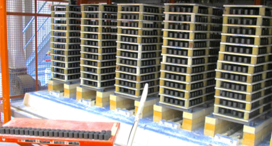
Metal oxide varistor blocks are the key component in modern day distribution class arresters and consist of a mixture of metal oxides, with ultra pure zinc oxide being the primary constituent. The other metal oxides exist in far smaller concentrations, down to only a few parts per million. These various metal oxides and other ingredients are mixed together in spray drying equipment designed to ensure a highly homogenous mixture and then compressed into blocks under pressure. Considerable know-how is required to adjust the compressive forces so as to ensure that blocks retain perfect homogeniety during this critical step. After pressing, subsequent production steps vary from one manufacturer to the next. Typically, blocks pass through a tunnel kiln at high temperatures in a process known as sintering and where their volume can be reduced by as much as 20 per cent. Blocks are subjected to acid treatment and electrodes are sprayed onto their surface. Finally, a high quality crystalline glass is applied followed by more treatment in the kiln.
Due to the specialized equipment and technical know-how required to produce consistently high-quality blocks at competitive cost, the business of producing these and the business of producing arresters took divergent roads. Only the largest suppliers of arresters could justify the investments needed to set-up sophisticated internal production lines for blocks while the remainder have found it more practical to simply purchase blocks externally.
A Relatively Low Cost Component Protecting a High Value Asset
The Back Story
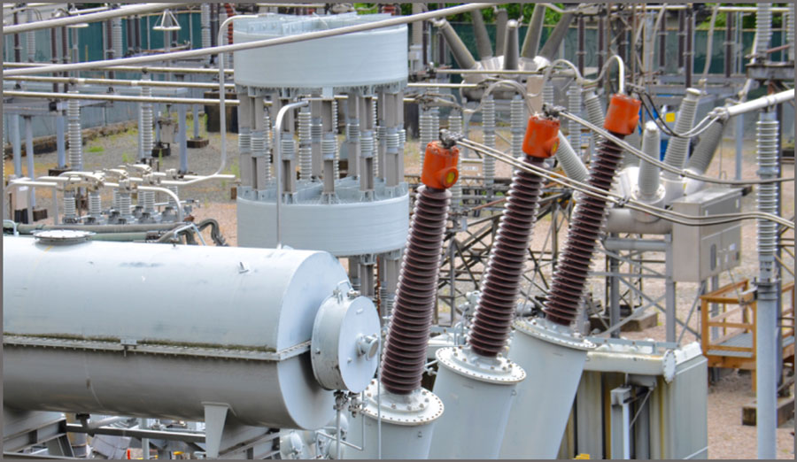
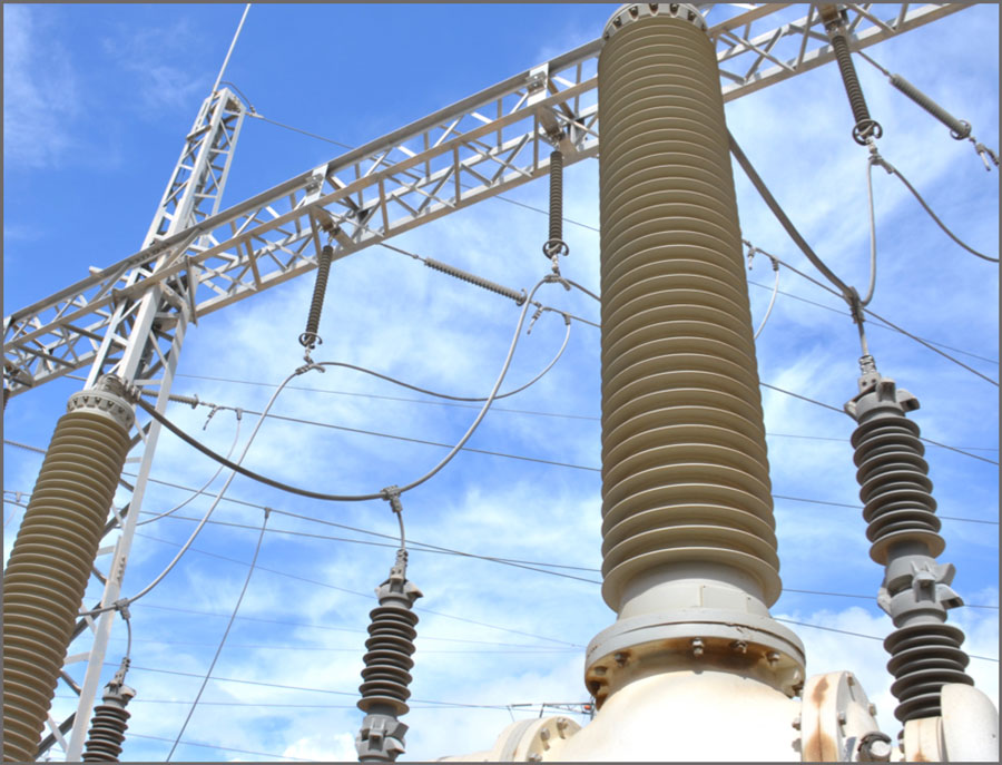
Bushings are devices that allow conductors to pass through the earthed walls of transformers, switchgear and substation structures. An integral part of this function involves meeting all the electrical, thermal and mechanical requirements of the application.
For example, bushings must provide reliable electrical insulation both internally (against breakdown) and externally (against flashover) of the conductor exposed to the rated voltage and also to periodic service overvoltages – even under contaminated conditions. Another key requirement is providing the mechanical strength needed to support the conductor as well as all external connections, including under short circuit and possible seismic forces. Moreover, a bushing must have the proper thermal design to avoid overheating of any of its elements and prevent onset of ageing phenomena inside its insulation – both at rated current and during short circuit events.
Like a surge arrester, the bushing is a relatively low cost component ensuring the safe operation of a comparatively high value asset. For example, while bushings typically account for less than 5 percent of the cost of a power transformer, their catastrophic failure can lead to total loss of the transformer and possibly other expensive equipment as well. Certain types of bushings can also pose a threat not only to substation personnel but also to adjoining residential areas.
In their early years, bushings were little more than hollow porcelains filled with transformer oil or solid resin surrounding the conductor. Such simple bulk and solid type bushings are in fact still applied at medium voltage levels. But as networks became more sophisticated, the need was recognized to better distribute the electric field generated across a bushing – especially at high voltages. This resulted in development of designs that are capacitance-graded. The basic principle is to distribute the natural field between conductor and earthed flange by employing intermediate conductive layers radially – to lower the field at the conductor and better utilize the insulation material – and also axially – to allow for higher flashover voltage values for any given arcing distance.
Originally, the materials used in the cylinders wound around the conductor included resin-bonded paper and carbon materials. These were later successively modified to designs involving less conductive grades of paper along with aluminum foil. One of the motivations behind development of field-graded bushings was reducing the diameters required for the porcelain housings. On ungraded bushings, electric field tends to be concentrated around the flanges and therefore risk of breakdown becomes high. On fine-graded bushings, stress is linearized and spread over a greater distance. This results in greater safety margin.
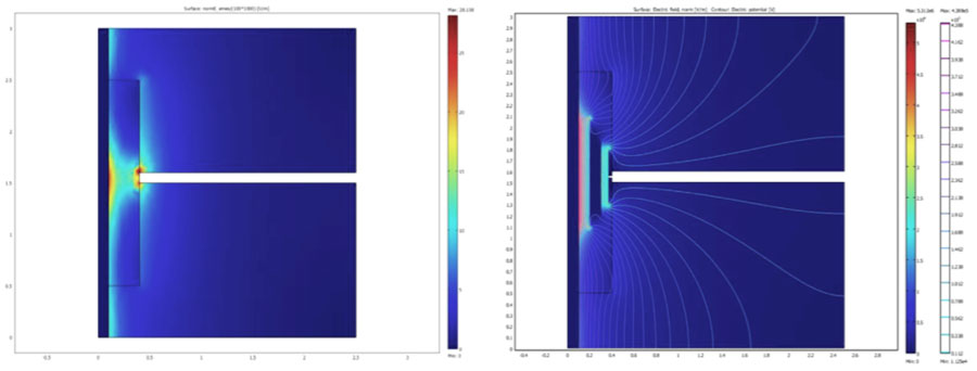
The basic principle in bushing design consists of a conductor surrounded by an insulating solid cylinder that is mechanically fixed to the earthed barrier. Distribution of electric field inside such a construction is highly non-uniform in terms of both axial and radial components. The highest stress concentration appears at the so-called ‘triple junction’ between the earthed wall, the insulating cylinder and the gaseous or liquid medium outside the bushing body. This localized high concentration of stress can trigger onset of partial discharges – often referred to as ‘gliding discharges’ since they have a strong capacitive coupling to the bushing’s internal conductor and therefore proceed along the insulating cylinder’s surface. They can lead to tracking along the bushing and even result in flashover. Initiation of gliding discharges as well as their subsequent development becomes easier when unit capacitance of the insulation (across its thickness) is greater. Therefore, voltage level for their ignition and propagation, which is virtually equal to flashover voltage, is determined by this parameter. This stands in contrast to other types of discharges, where the typical controlling parameter is electrode separation distance. Because of such considerations, the best way to increase a bushing’s flashover withstand voltage is by improving electric field distribution along its surface. This can be achieved in a number of ways. In the case of higher voltages, the most effective means is through capacitive control for AC applications and resistive control for DC applications. Capacitive control is based on inserting metallic screens into the solid insulation of the bushing, essentially forming a system of in-series connected capacitors whose magnitude depends on geometrical arrangement. The most frequently used and effective solution is when series capacitances are maintained at equal levels.
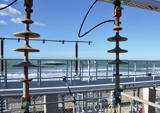
‘Torture Chamber’ for Electrical Insulation
The Back Story
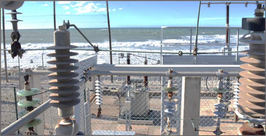
In spite of years spent developing sophisticated laboratory tests to reproduce the possible stresses faced by components in service, experience at an outdoor test station is still regarded as the definitive measure of expected field performance under adverse conditions. For this reason, there is continued interest in research at test stations where the principal characteristic is cycles of severe pollution accumulation and natural cleaning that are difficult to replicate in a laboratory setting.
One such test station is located near the French port of Marseille, on the Mediterranean coast. What makes the site so suitable for its purpose is that it combines heavy maritime and industrial pollution, thereby creating a particularly demanding service environment. There is also intense UV radiation spread over the entire year. If a component performs well at this test station, it is reasonable to believe that it will do so in the field as well.
Martigues Test Station is one of the world’s longest serving for electrical equipment and components. Established primarily to study behavior of glass and porcelain insulators under maritime and industrial pollution, it is only meters from the sea and near petrochemical and refining complexes making it a true test of electrical insulation under some of the most challenging service conditions.
Starting in the 1990s, research performed at Martigues began to shift from ceramic and more toward composite type insulation. One of the goals was to compare findings from accelerated ageing tests in the laboratory with those obtained in this natural setting. It was hoped that this would help confirm whether the acceleration factors being proposed were reasonable or not. Eventually this effort was discontinued, once it was realized that acceleration factors cannot be generalized but rather depend on specific insulator design and material. Today, Martigues is mainly a developmental test station where new designs and insulation materials can be subjected to worst-case service conditions. Another change over the years has been the expansion of test objects from mainly line insulators to include equipment such as surge arresters, cable accessories and CTs.
Different Preferences for Breaker Bushing Insulation
The Back Story
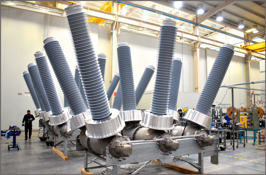
The Mexican market for HV breakers has been transitioning slowly from a mainly dead tank market to one that is now increasingly live tank. Preference for one style over the other involves a number of offsetting technical and economic considerations. While a live tank breaker typically costs less than half of an equivalent dead tank type, it comes with the added cost to install three current transformers on each side of its breaking chamber. By contrast, a dead tank breaker already integrates all the CTs and also offers superior seismic performance. In terms of transport and handling requirements, a live tank breaker for 145 kV weighs only about 1300 kg compared to some 3000 kg for a dead tank unit of same voltage class.
One of the important technical trends in breakers over the past decade relates to the type of bushings requested by end customers. In Mexico, for example, there remains a strong preference for porcelain over silicone-housed bushings. The only exceptions are for service in heavily contaminated environments such as near petrochemical installations or along the coast. By contrast, other countries such as Australia have moved decisively toward composite bushings not for pollution performance but rather because of laws mandating safety in the event of explosive failure. Similarly, power suppliers in places such as Guatemala prefer silicone housings due to their superior seismic withstand.
End customers at power companies seldom specify a particular supplier for the bushings and are usually content to leave this choice to the breaker manufacturer. Still, insulators are considered a strategic item at any breaker plant and often ordered through a dedicated sourcing department. While sometimes referred to as ‘commodities’, these are in fact highly engineered to meet the demanding electrical and mechanical requirements of a breaker application. For example, one past problem related not to issues with the porcelain body but rather to how well it was attached to the flange. Sulphur cement has since been replaced by Portland cement to improve bonding strength. If there is ever a problem with a breaker’s bushings, it will typically be in this interface between porcelain and flange such that there may be slight movement after several years in service. Eventually, such a problem can lead to leakage past the O-ring.
Pollution Environment Required RTV Coated Composite Bushings
The Back Story
One of the challenges confronted by maintenance staff at Israel Electric has been at the 170 kV Alon Tabor Substation, site of the utility’s first installation of silicone-housed bushings. Commissioned in 2000, the hybrid GIS station underwent a sudden change in pollution exposure eight years later due to construction of a nearby gas turbine generation facility. The cooling towers at this plant employ saline water with conductivity estimated at as much as 30,000 mS/cm, which is then blown by prevailing winds as a fine spray toward the station. This makes the station’s already dusty service environment worse and pollution flashover incidents have occurred on porcelain-housed equipment.
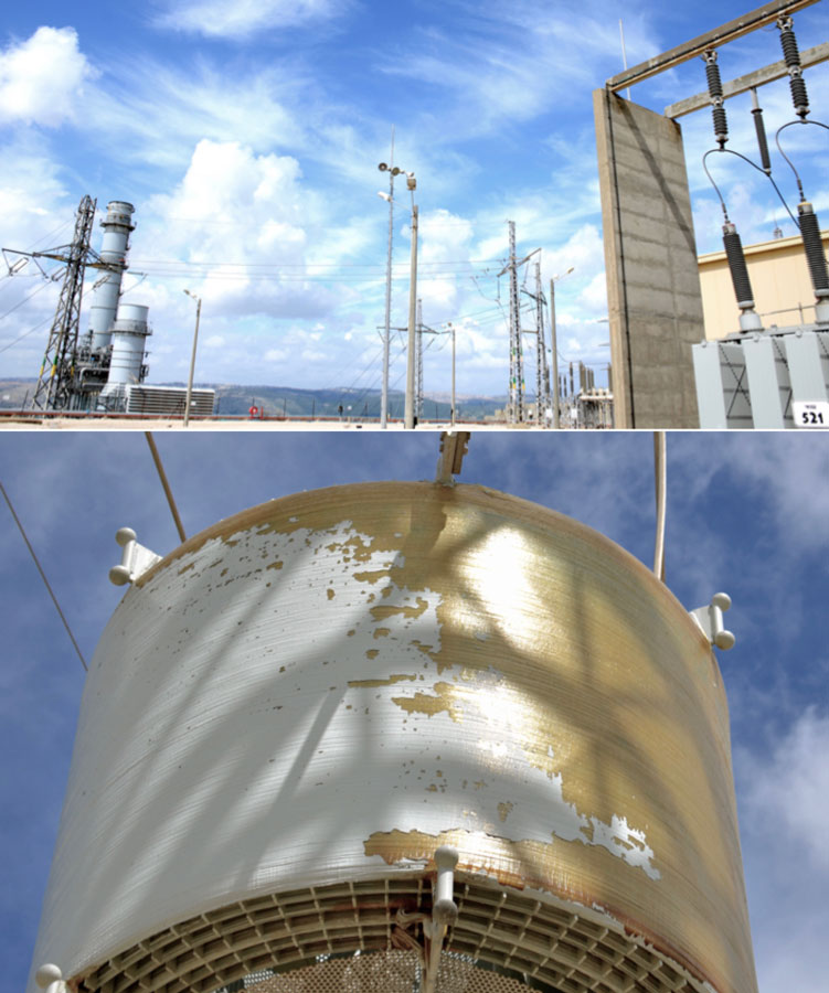
These problems eventually led staff to grow concerned that the silicone-housed GIS bushings might be ageing prematurely in the aggressive service environment – in spite of the fact that there had not been any flashovers or anything unusual yet reported. Indeed, close-up inspection revealed what appeared to be localized patches of erosion on shed edges and along the trunk near the bottom flange on 2 of the station’s 42 bushings. Based on this, one of the units was removed and sent to the utility’s R&D laboratory for thorough investigation. It was concluded that droplets of water falling on the bushings might be causing tiny pinholes on some sheds due to their acidity. This conclusion was reinforced by an unrelated finding from a maintenance team that visited Alon Tabor as part of their usual monitoring duties. Visual inspection using high-powered binoculars revealed that water vapor from the cooling towers was also causing expansion damage to the cement in porcelain string insulators used between towers at the substation. To avoid risk of continuing degradation, a decision was made to apply RTV coatings to the bushings – in spite of their being silicone-housed. Although this practice is not common in the industry, applying the coating was regarded as offering an immediate solution to the pinholes.
The topic of applying RTV coatings to silicone composite insulators still remains an open question since there seems relatively little field experience on which to base conclusions. While silicone insulator manufacturers may question such a need, suppliers of coatings take a different perspective and regard addition of RTV material as a tool to enhance the inherent hydrophobicity of silicone composite insulators. Some even point to projects where customers have insisted on coating silicone insulators before they were put into service.
Substation Marked World’s First Commercial Application at 1000 kV
The Back Story
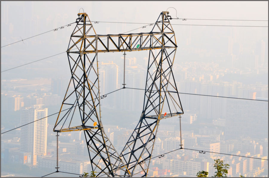
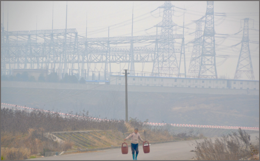
‘Juxtaposition’ is a term describing two images that appear together but inherently conflict with one another, as in the above photo: in the foreground an elderly lady who, as for time immemorial, relies only on the power of her back and legs to transport goods; looming in the smog shrouded background, a massive substation transmitting enough power to light the homes of millions. That is juxtaposition.
In January 2009, China’s first commercial 1000 kV system was put into operation with the goal of eventually linking the North China Power Grid with that of Central China. This ‘pilot demonstration project’ by the State Grid Corporation of China was regarded as especially significant since it promised to have great impact on how electric power would one day move across the world’s most populous nation. For example, apart from the obvious advantage of allowing better integration of its vast network, UHV power transfer would also mean that China could better plan large-scale generation projects and reduce dependence on relatively small, coal-fired power stations.
SGCC’s 1000 kV UHV AC Test Demonstration Project starts at Jindongnan Substation and passes through the Nanyang Switching Station in Henan Province before ending at Jingmen Substation. With a maximum operating voltage of 1100 kV, the single circuit line of 654 km comprises 1280 towers. Substation capacity is 6 million kVa. The project faced many hurdles when first approved. There was almost no equipment available at this voltage level with any demonstrated service experience. Nor were there relevant standards to follow in regard to substation design as well as for key components such as surge arresters, CVTs or oil-paper bushings. On top of these obstacles, there was also no relevant experience available when it came to construction, which therefore had to rely on experience with 750 kV and 500 kV projects.
To proceed with the design phase, some 50 key technologies had to be investigated, including insulation coordination, electromagnetic environment, lightning protection, structural loads, and reliability. Specification then emphasized local suppliers for all key equipment, from the special low noise 3-phase shunt reactors with 1100 kV rated voltage and 320 MVar capacity, to the single-phase transformers each with rated voltage of 1050 kV, weighing some 1575 metric tons and developed to yield a capacity of 334 MVA in their single column windings, to the unique hybrid GIS breaker, measuring 10 m in length and claimed to be one of the world’s most technologically advanced.
Among the unique items utilized at Jingmen Substation that set it apart from its sister station, Jindongnan, are six 1000 kV composite GIS bushings. While at Jindongnan the GIS bushings are made with porcelain housings, the 10.8 m high lead-out bushings at Jingmen are all constructed using silicone composite housings – reportedly the first practical application of this technology at 1000 kV. The production lead time for the huge housings proved to be only about a month – considerably shorter than would have been required for equivalent porcelain – while cost was claimed to have been reduced by as much as 65 percent per unit.
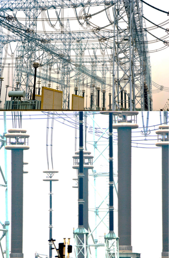
The 1000 kV hollow core composite insulators at Jingmen are typical of this technology, comprising an epoxy glass fibre tube, silicone rubber sheds and special end fittings. Applied as the outer insulation for the substation’s unique HGIS equipment, these were designed to operate over a range of -60° to +50°C, while creepage was selected as applicable for the local service conditions, typical of a Class IV pollution area. Development of hollow core composite insulator technology up to 1000 kV is widely regarded as offering significant benefits not only from the standpoint of reduced manufacturing time and costs but also in terms of improved performance. For example, PD levels on these composite housings are claimed to be less than 2 pC versus an estimated 10 pC or higher for porcelain. In terms of mechanical behaviour, inner pressure damage/failure limit is said to exceed 4 Mpa (compared to 2.6 Mpa for porcelain), meaning increased safety for personnel as well as lower risk of damage from explosion. Moreover, cantilever bending tests have demonstrated that the bushings can withstand 54 kN (583.2 kNm) – surpassing the minimum failure bending load of 45 kN specified by SGCC.
Wildlife Interaction Caused Catastrophic Failure of Porcelain Bushings
The Back Story
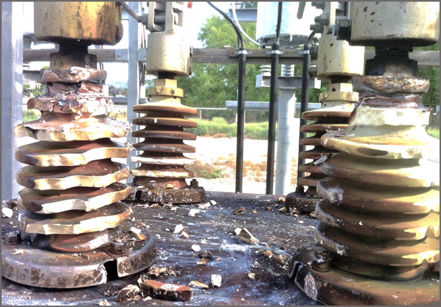
Among the most vulnerable links in any power network are the points of interaction between live equipment and wildlife – from birds to scavenging carnivores. Taken together, these creatures present a constant threat to the safe operation of network assets. In the case of bushings, for example, shock waves from a wildlife-induced flashover can blow porcelain housings into shrapnel that threatens safety and impacts nearby equipment.
The global economy is said to suffer huge losses each year due to sudden power disruptions and data suggests that as much as 12 percent of these are due to wildlife. If outages classified as ‘source unknown’ are factored in, most of which are thought to involve wildlife, the annual impact is even greater. Moreover, this risk is only growing given the focus on lowering costs, saving space and making electrical infrastructure less visible through compaction – in the process also reducing the distances that need to be breached to create faults. It has been estimated that if installations from 5 kV to 38 kV, where clearances are most at threat, would be selectively equipped with wildlife protection products such risk could be reduced by as much as 80 per cent.